Skip to product information
1 of 12

PayPal, credit cards. Download editable-PDF and invoice in 1 second!

GB/T 22670-2008 English PDF (GB/T22670-2008)

GB/T 22670-2008 English PDF (GB/T22670-2008)

Regular price $395.00
Regular price Sale price $395.00
Sale Sold out
Shipping calculated at checkout.
GB/T 22670-2008: Test procedures for converter-fed three phase cage induction motors
Delivery: 9 seconds. Download (and Email) true-PDF + Invoice.
Newer version: (Replacing this standard) GB/T 22670-2018
Get Quotation: Click GB/T 22670-2008 (Self-service in 1-minute)
Historical versions (Master-website): GB/T 22670-2018
Preview True-PDF (Reload/Scroll-down if blank)


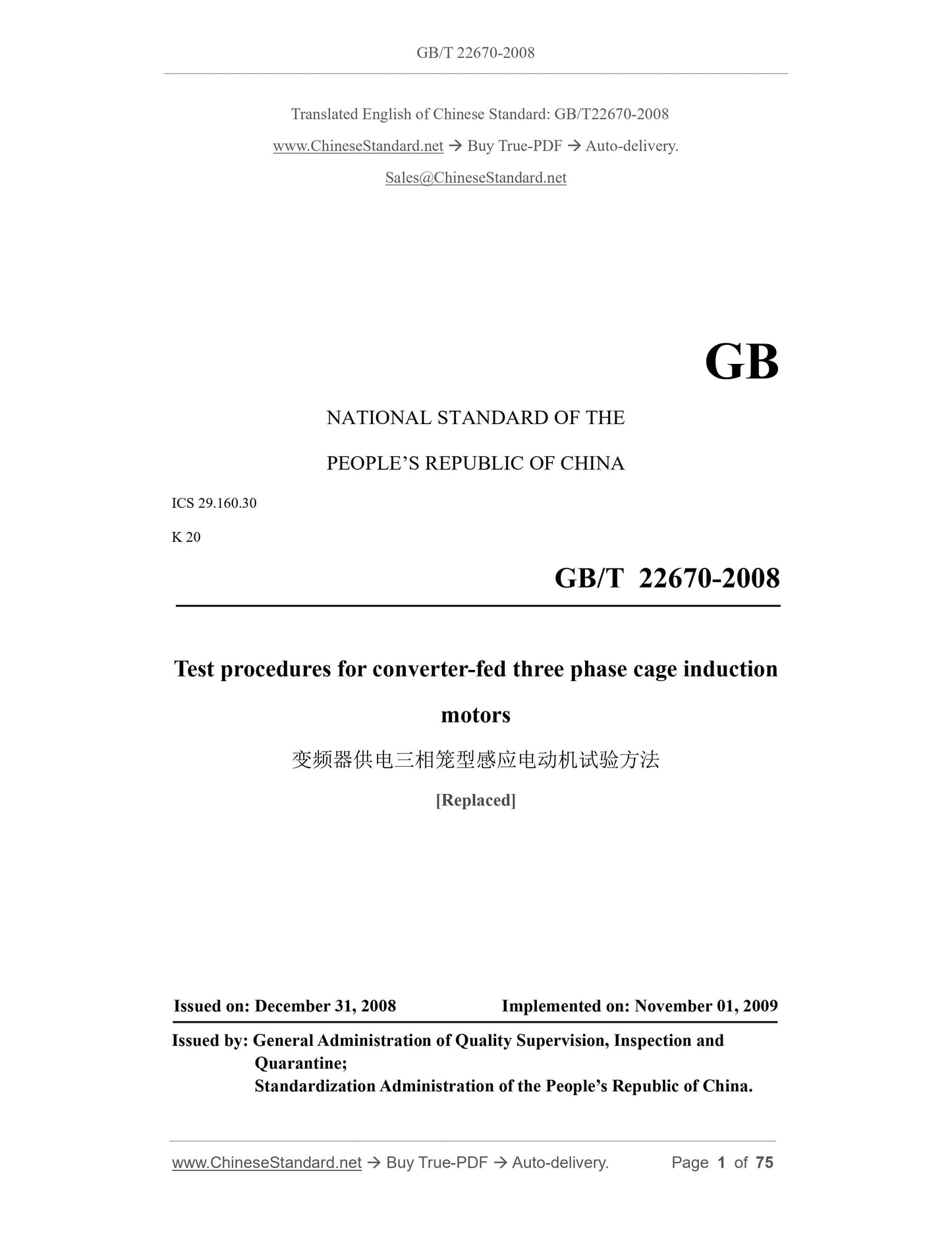
GB/T 22670-2008
GB
NATIONAL STANDARD OF THE
PEOPLE’S REPUBLIC OF CHINA
ICS 29.160.30
K 20
Test procedures for converter-fed three phase cage induction
motors
[Replaced]
ISSUED ON: DECEMBER 31, 2008
IMPLEMENTED ON: NOVEMBER 01, 2009
Issued by: General Administration of Quality Supervision, Inspection and
Quarantine;
Standardization Administration of the People’s Republic of China.
Table of Contents
Foreword ... 3
1 Scope ... 4
2 Normative references ... 4
3 Terms and definitions, symbols ... 5
4 Test requirements ... 10
5 Test preparation ... 13
6 No-load test ... 16
7 Locked-rotor test ... 18
8 Load test ... 21
9 Determination of loss (applicable to voltage source converter) ... 23
10 Determination of efficiency ... 29
11 Base rating thermal test ... 34
12 Determination of maximum torque ... 45
13 Determination of minimum torque ... 49
14 Other tests ... 50
15 Calculation format ... 57
Appendix A (Normative) Correction method of instrument loss and error ... 67
Appendix B (Normative) Correction of dynamometer’s torque reading ... 72
Appendix C (Informative) Linear regression analysis ... 74
Test procedures for converter-fed three phase cage induction
motors
1 Scope
This standard specifies the test procedures for converter-fed three-phase cage induction
motors.
This standard applies to converter-fed three-phase cage induction motors.
This standard does not apply to traction motors.
2 Normative references
The terms in the following documents become the terms of this standard by reference
to this standard. For dated references, all subsequent amendments (not including errata
content) or revisions do not apply to this standard. However, parties to agreements that
are based on this standard are encouraged to study whether the latest versions of these
documents can be used. For undated references, the latest edition applies to this
Standard.
GB 755-2008, Rotating Electrical Machines - Rating and Performance (IEC 60034-
1:2004, IDT)
GB/T 755.2-2003, Methods for determining losses and efficiency of rotating
electrical machinery from tests (excluding machines for traction vehicles) (IEC
60034-2:1972, IDT)
GB/T 1032-2005, Test procedures for three-phase induction motors
GB 10068-2008, Mechanical vibration of certain machines with shaft heights 56 mm
and higher-measurement evaluation and limits of vibration severity (IEC 60034-
14:2003, IDT)
GB/T 10069.1-2006, Measurement of airborne noise emitted by rotating electrical
machines and the noise limits - Part 1: Method for the measurement of airborne noise
emitted by rotating electrical machines (ISO 1680:1999, MOD)
IEC 60034-2-1:2007, Rotating electrical machines - Part 2-1: Standard methods for
determining losses and efficiency from tests (excluding machines for traction
vehicles)
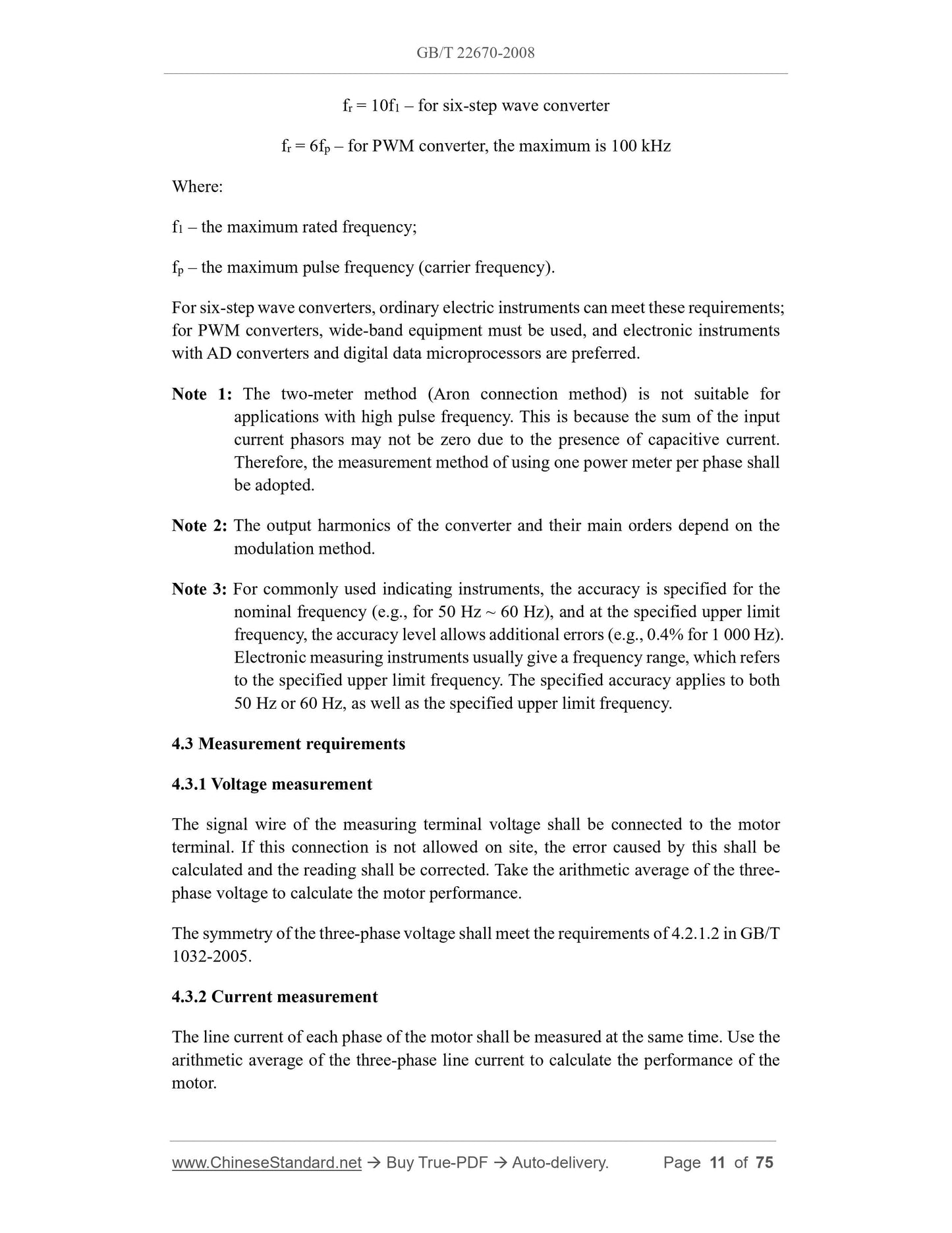
fr = 10f1 – for six-step wave converter
fr = 6fp – for PWM converter, the maximum is 100 kHz
Where:
f1 – the maximum rated frequency;
fp – the maximum pulse frequency (carrier frequency).
For six-step wave converters, ordinary electric instruments can meet these requirements;
for PWM converters, wide-band equipment must be used, and electronic instruments
with AD converters and digital data microprocessors are preferred.
Note 1: The two-meter method (Aron connection method) is not suitable for
applications with high pulse frequency. This is because the sum of the input
current phasors may not be zero due to the presence of capacitive current.
Therefore, the measurement method of using one power meter per phase shall
be adopted.
Note 2: The output harmonics of the converter and their main orders depend on the
modulation method.
Note 3: For commonly used indicating instruments, the accuracy is specified for the
nominal frequency (e.g., for 50 Hz ~ 60 Hz), and at the specified upper limit
frequency, the accuracy level allows additional errors (e.g., 0.4% for 1 000 Hz).
Electronic measuring instruments usually give a frequency range, which refers
to the specified upper limit frequency. The specified accuracy applies to both
50 Hz or 60 Hz, as well as the specified upper limit frequency.
4.3 Measurement requirements
4.3.1 Voltage measurement
The signal wire of the measuring terminal voltage shall be connected to the motor
terminal. If this connection is not allowed on site, the error caused by this shall be
calculated and the reading shall be corrected. Take the arithmetic average of the three-
phase voltage to calculate the motor performance.
The symmetry of the three-phase voltage shall meet the requirements of 4.2.1.2 in GB/T
1032-2005.
4.3.2 Current measurement
The line current of each phase of the motor shall be measured at the same time. Use the
arithmetic average of the three-phase line current to calculate the performance of the
motor.
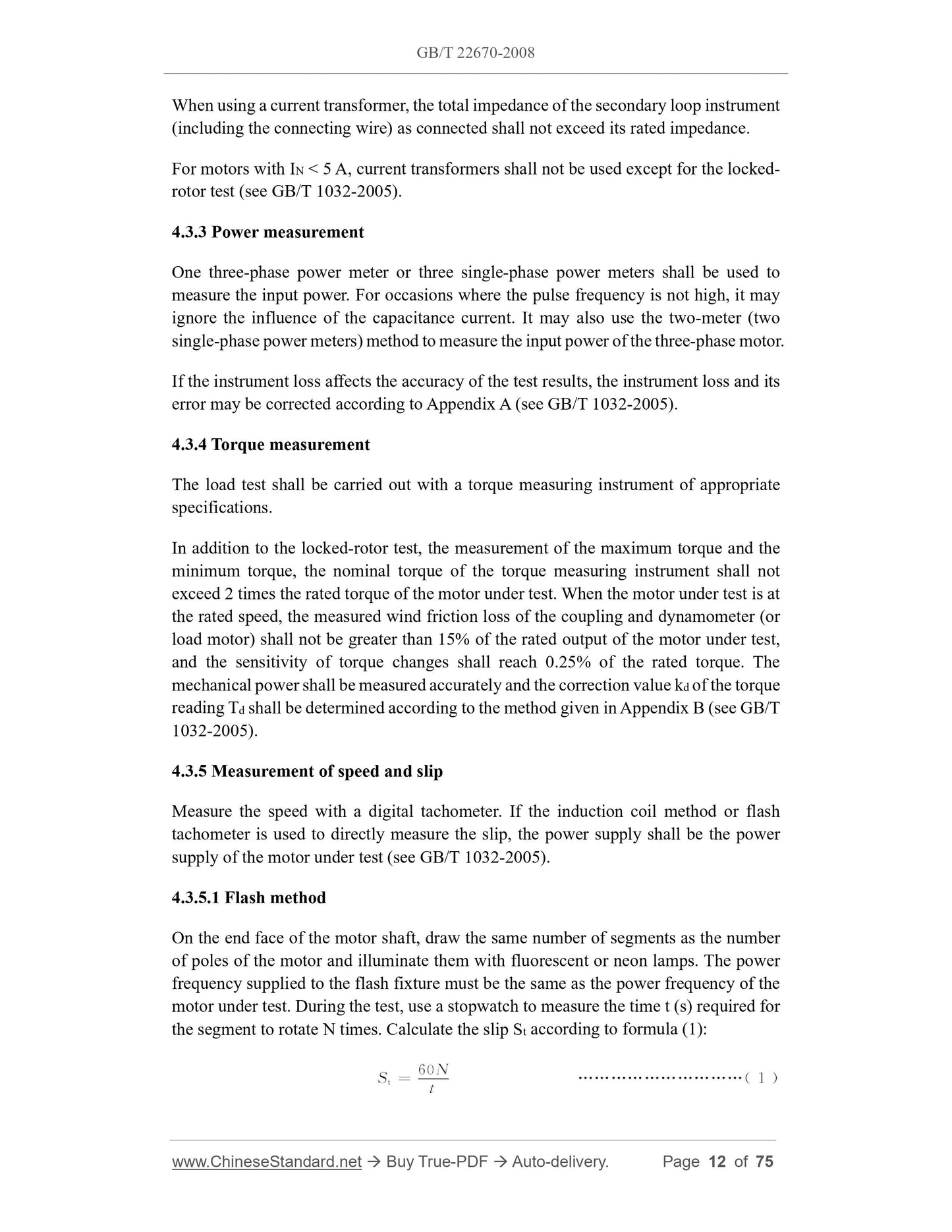
When using a current transformer, the total impedance of the secondary loop instrument
(including the connecting wire) as connected shall not exceed its rated impedance.
For motors with IN < 5 A, current transformers shall not be used except for the locked-
rotor test (see GB/T 1032-2005).
4.3.3 Power measurement
One three-phase power meter or three single-phase power meters shall be used to
measure the input power. For occasions where the pulse frequency is not high, it may
ignore the influence of the capacitance current. It may also use the two-meter (two
single-phase power meters) method to measure the input power of the three-phase motor.
If the instrument loss affects the accuracy of the test results, the instrument loss and its
error may be corrected according to Appendix A (see GB/T 1032-2005).
4.3.4 Torque measurement
The load test shall be carried out with a torque measuring instrument of appropriate
specifications.
In addition to the locked-rotor test, the measurement of the maximum torque and the
minimum torque, the nominal torque of the torque measuring instrument shall not
exceed 2 times the rated torque of the motor under test. When the motor under test is at
the rated speed, the measured wind friction loss of the coupling and dynamometer (or
load motor) shall not be greater than 15% of the rated output of the motor under test,
and the sensitivity of torque changes shall reach 0.25% of the rated torque. The
mechanical power shall be measured accurately and the correction value kd of the torque
reading Td shall be determined according to the method given in Appendix B (see GB/T
1032-2005).
4.3.5 Measurement of speed and slip
Measure the speed with a digital tachometer. If the induction coil method or flash
tachometer is used to directly measure the slip, the power supply shall be the power
supply of the motor under test (see GB/T 1032-2005).
4.3.5.1 Flash method
On the end face of the motor shaft, draw the same number of segments as the number
of poles of the motor and illuminate them with fluorescent or neon lamps. The power
frequency supplied to the flash fixture must be the same as the power frequency of the
motor under test. During the test, use a stopwatch to measure the time t (s) required for
the segment to rotate N times. Calculate the slip St according to formula (1):
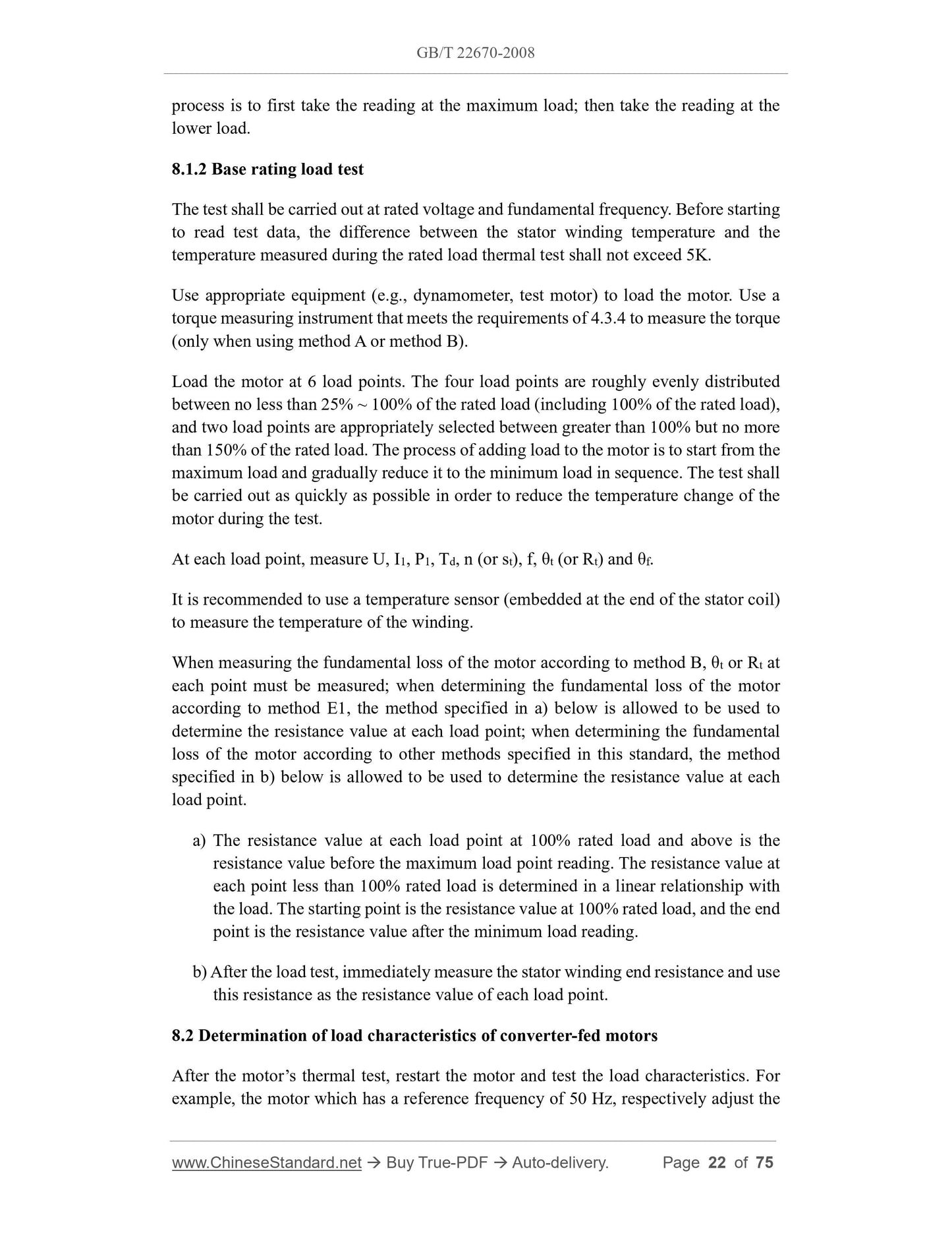
process is to first take the reading at the maximum load; then take the reading at the
lower load.
8.1.2 Base rating load test
The test shall be carried out at rated voltage and fundamental frequency. Before starting
to read test data, the difference between the stator winding temperature and the
temperature measured during the rated load thermal test shall not exceed 5K.
Use appropriate equipment (e.g., dynamometer, test motor) to load the motor. Use a
torque measuring instrument that meets the requirements of 4.3.4 to measure the torque
(only when using method A or method B).
Load the motor at 6 load points. The four load points are roughly evenly distributed
between no less than 25% ~ 100% of the rated load (including 100% of the rated load),
and two load points are appropriately selected between greater than 100% but no more
than 150% of the rated load. The process of adding load to the motor is to start from the
maximum load and gradually reduce it to the minimum load in sequence. The test shall
be carried out as quickly as possible in order to reduce the temperature change of the
motor during the test.
At each load point, measure U, I1, P1, Td, n (or st), f, θt (or Rt) and θf.
It is recommended to use a temperature sensor (embedded at the end of the stator coil)
to measure the temperature of the winding.
When measuring the fundamental loss of the motor according to method B, θt or Rt at
each point must be measured; when determining the fundamental loss of the motor
according to method E1, the method specified in a) below is allowed to be used to
determine the resistance value at each load point; when determining the fundamental
loss of the motor according to other methods specified in this standard, the method
specified in b) below is allowed to be used to determine the resistance value at each
load point.
a) The resistance value at each load point at 100% rated load and above is the
resistance value before the maximum load point reading. The resistance value at
each point less than 100% rated load is determined in a linear relationship with
the load. The starting point is the resistance value at 100% rated load, and the end
point is the resistance value after the minimum load reading.
b) After the load test, immediately measure the stator winding end resistance and use
this resistance as the resistance value of each load point.
8.2 Determination of load characteristics of converter-fed motors
After the motor’s thermal test, restart the motor and test the load characteristics. For
example, the motor which has a reference frequency of 50 Hz, respectively adjust the
In motors powered by converters, voltage harmonics and current harmonics cause
additional iron losses and winding I2R losses in the motor stator and rotor. This
additional loss is collectively called harmonic loss.
As far as motors powered by voltage source converters are concerned, many tests have
proven that the size of harmonic losses has nothing to do with load changes (see IEC
TS 60034-17:2006, Chapter 5).
The loss of the motor consists of two parts: fundamental loss and harmonic loss.
10.2.2.1 Harmonic losses
The harmonic loss Pbh is determined according to 6.2.2.
10.2.2.2 Fundamental losses
The motor under test is powered by a sine wave power supply, and the fundamental loss
is determined according to the following methods specified in GB/T 1032-2005:
a) Method B (see 10.4);
b) Method E1 (see 10.5);
c) Method F1 (see 10.6);
d) Method G1 (see 10.7);
e) Method H (see 10.8).
10.2.2.3 Determination of efficiency
The corrected sum of fundamental losses PT is determined according to formula (34),
the corrected total loss ΣP of the motor is determined according to formula (35), and
the efficiency of the motor is determined according to formula (38).
10.3 Method A – input-output method (applicable to voltage and current source
converters)
This method uses the ratio of measured output power to input power to calculate
efficiency. Usually used for motors with an efficiency not greater than 90% (see 7.1 in
GB/T 755.2-2003).
10.3.1 Test procedure
During the test, the motor under test is powered by the converter power supply and
reaches a thermally stable state under rated load. Carry out load test according to the
method specified in 8.1.2.
10.3.2 Calculation format
R1 – the initial end resistance of the winding when the temperature is θ1, in ohms (Ω);
θa – the cooling medium temperature at the end of the thermal test, in degrees Celsius
(°C);
θ1 – the winding temperature when measuring the initial end resistance R1, in degrees
Celsius (°C);
K1 – constant. For copper windings, it is 235; for aluminum windings, it is 225, unless
otherwise specified.
Since the deviation of the measured resistance will cause a large error when determining
the temperature, the instrument required in 4.3.6 of GB/T 1032-2005 shall be used to
measure the winding resistance. If possible, a second instrument can be used for
inspection. The initial resistance and the resistance at the end of the test shall be
measured using the same instrument.
11.1.3.3 Embedded thermometer method
This method uses a thermocouple installed in the motor or a resistance thermometer to
measure the temperature.
Specially designed instruments shall be used with resistance thermometers to prevent
the heating of the resistance thermometer from introducing significant errors or
damaging the instrument during measurements. Many ordinary resistance-type
measuring devices may not be suitable because considerable current may flow through
the resistor element during the measurement.
11.1.4 Temperature reading
11.1.4.1 General description
The following subclauses introduce 3 temperature measurement methods for
determining the temperature of the motor’s windings, stator core, entered cooling
medium, and discharged cooling medium after being heated. Each measurement
method has its own characteristics and is suitable for measuring the temperature of
specific parts of the motor.
11.1.4.2 Thermometer method
During the thermal test, the temperature of the following components can be measured
using the thermometer method (see 11.1.3.1). If specified, measurements can be made
after shutdown.
a) stator coil, at least in 2 locations;
b) stator core, for large and medium-sized motors, at least in 2 locations;
c) ambient temperature;
d) the air discharged from the machine base or exhaust ventilation duct or the internal
cooling medium discharged from the motor with a circulating cooling system to
the cooler inlet;
e) machine base;
f) bearings (if they are motor components).
The temperature sensitive element shall be placed where the highest temperature can
be measured. For the temperature of air or other cooling media in the inc...
View full details