1
/
of
12
www.ChineseStandard.us -- Field Test Asia Pte. Ltd.
GB/T 22670-2018 English PDF (GB/T22670-2018)
Regular price
$695.00
Regular price
Sale price
$695.00
Unit price
/
per
Shipping calculated at checkout.
Couldn't load pickup availability
GB/T 22670-2018: Test procedures for converter-fed three phase cage induction motors
Delivery: 9 seconds. Download (& Email) true-PDF + Invoice.
Get Quotation: Click GB/T 22670-2018 (Self-service in 1-minute)
Historical versions (Master-website): GB/T 22670-2018
Preview True-PDF (Reload/Scroll-down if blank)
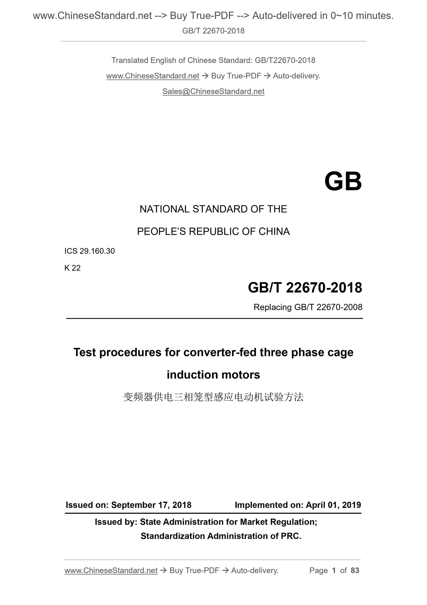
GB/T 22670-2018
GB
NATIONAL STANDARD OF THE
PEOPLE’S REPUBLIC OF CHINA
ICS 29.160.30
K 22
Replacing GB/T 22670-2008
Test procedures for converter-fed three phase cage
induction motors
ISSUED ON: SEPTEMBER 17, 2018
IMPLEMENTED ON: APRIL 01, 2019
Issued by: State Administration for Market Regulation;
Standardization Administration of PRC.
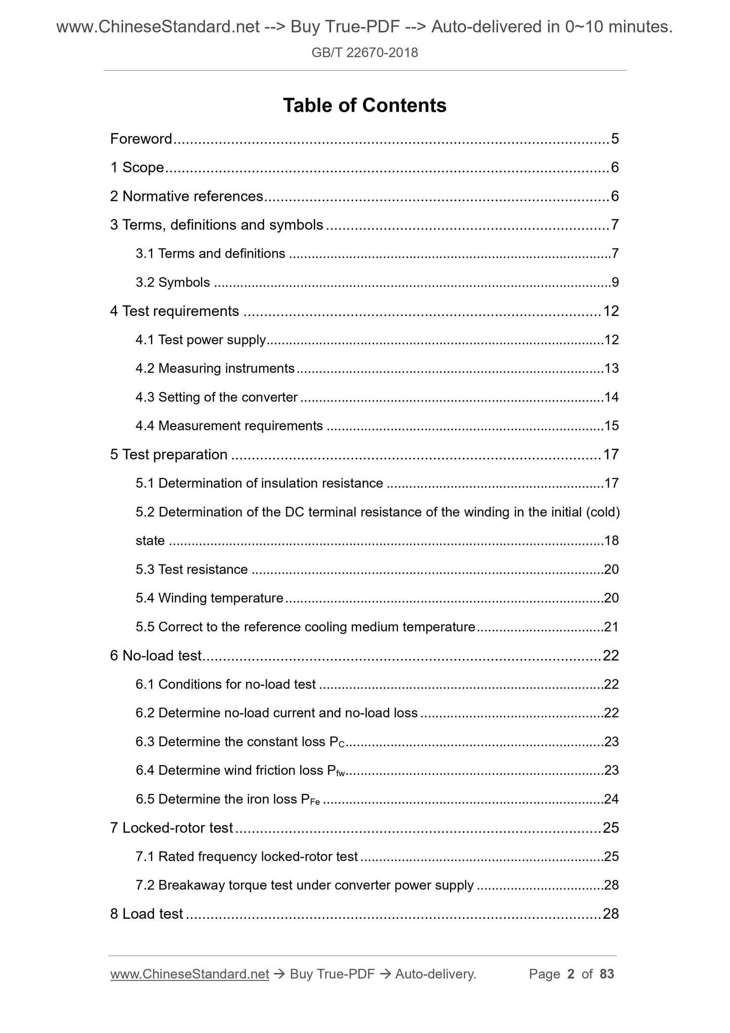
Table of Contents
Foreword ... 5
1 Scope ... 6
2 Normative references ... 6
3 Terms, definitions and symbols ... 7
3.1 Terms and definitions ... 7
3.2 Symbols ... 9
4 Test requirements ... 12
4.1 Test power supply ... 12
4.2 Measuring instruments ... 13
4.3 Setting of the converter ... 14
4.4 Measurement requirements ... 15
5 Test preparation ... 17
5.1 Determination of insulation resistance ... 17
5.2 Determination of the DC terminal resistance of the winding in the initial (cold)
state ... 18
5.3 Test resistance ... 20
5.4 Winding temperature ... 20
5.5 Correct to the reference cooling medium temperature ... 21
6 No-load test ... 22
6.1 Conditions for no-load test ... 22
6.2 Determine no-load current and no-load loss ... 22
6.3 Determine the constant loss PC ... 23
6.4 Determine wind friction loss Pfw ... 23
6.5 Determine the iron loss PFe ... 24
7 Locked-rotor test ... 25
7.1 Rated frequency locked-rotor test ... 25
7.2 Breakaway torque test under converter power supply ... 28
8 Load test ... 28
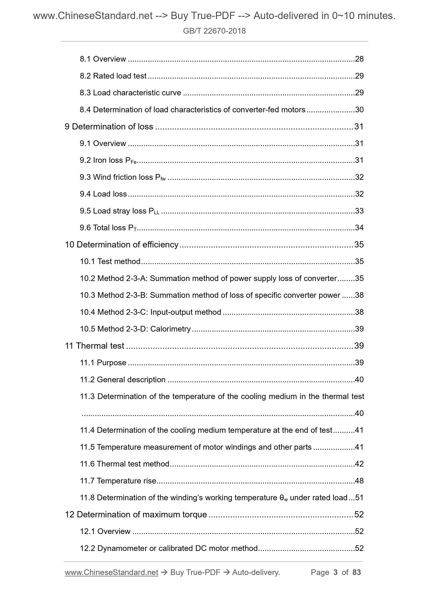
8.1 Overview ... 28
8.2 Rated load test ... 29
8.3 Load characteristic curve ... 29
8.4 Determination of load characteristics of converter-fed motors ... 30
9 Determination of loss ... 31
9.1 Overview ... 31
9.2 Iron loss PFe ... 31
9.3 Wind friction loss Pfw ... 32
9.4 Load loss ... 32
9.5 Load stray loss PLL ... 33
9.6 Total loss PT ... 34
10 Determination of efficiency ... 35
10.1 Test method ... 35
10.2 Method 2-3-A: Summation method of power supply loss of converter ... 35
10.3 Method 2-3-B: Summation method of loss of specific converter power ... 38
10.4 Method 2-3-C: Input-output method ... 38
10.5 Method 2-3-D: Calorimetry ... 39
11 Thermal test ... 39
11.1 Purpose ... 39
11.2 General description ... 40
11.3 Determination of the temperature of the cooling medium in the thermal test
... 40
11.4 Determination of the cooling medium temperature at the end of test ... 41
11.5 Temperature measurement of motor windings and other parts ... 41
11.6 Thermal test method ... 42
11.7 Temperature rise ... 48
11.8 Determination of the winding’s working temperature θw under rated load ... 51
12 Determination of maximum torque ... 52
12.1 Overview ... 52
12.2 Dynamometer or calibrated DC motor method ... 52
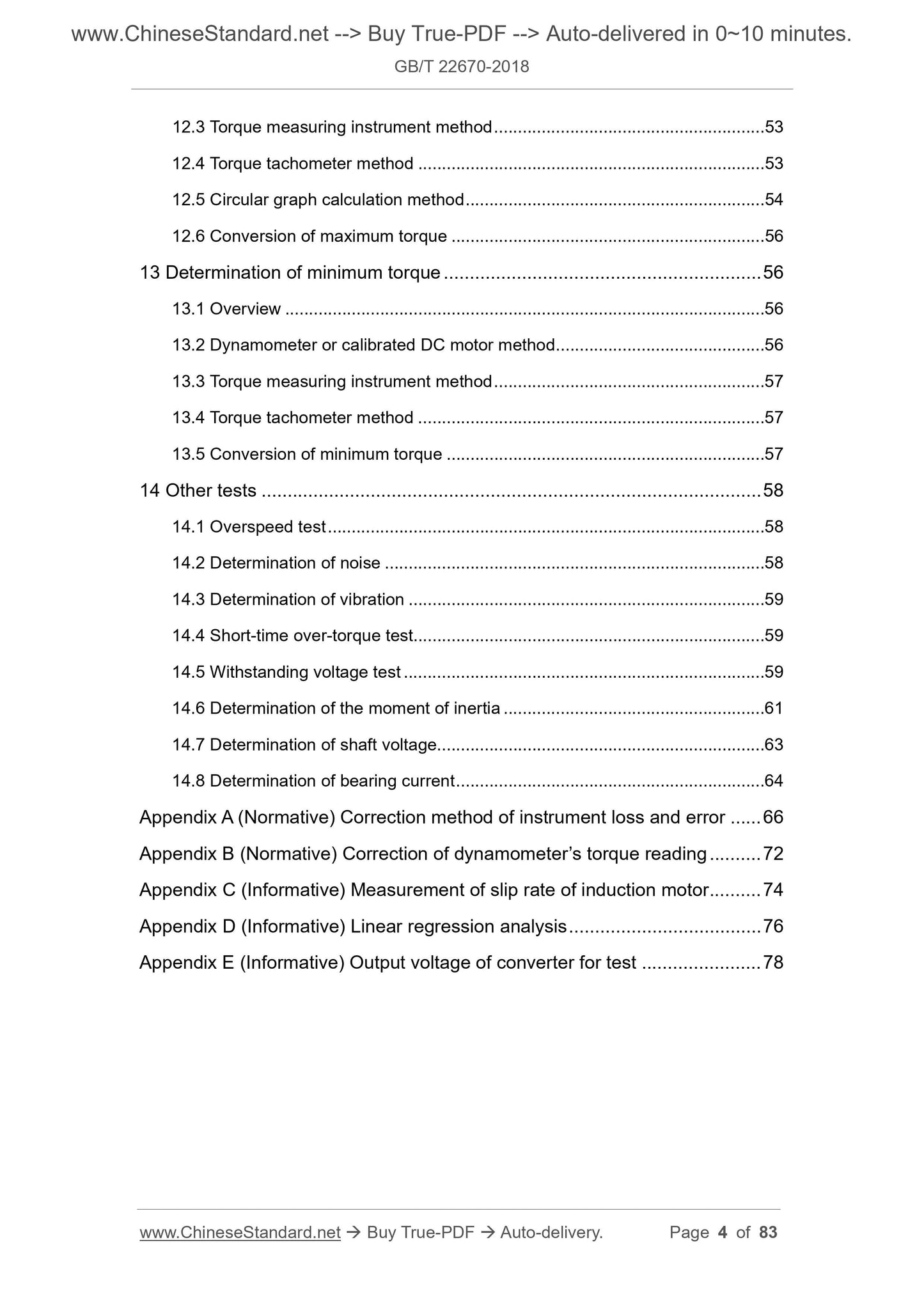
12.3 Torque measuring instrument method ... 53
12.4 Torque tachometer method ... 53
12.5 Circular graph calculation method ... 54
12.6 Conversion of maximum torque ... 56
13 Determination of minimum torque ... 56
13.1 Overview ... 56
13.2 Dynamometer or calibrated DC motor method ... 56
13.3 Torque measuring instrument method ... 57
13.4 Torque tachometer method ... 57
13.5 Conversion of minimum torque ... 57
14 Other tests ... 58
14.1 Overspeed test ... 58
14.2 Determination of noise ... 58
14.3 Determination of vibration ... 59
14.4 Short-time over-torque test ... 59
14.5 Withstanding voltage test ... 59
14.6 Determination of the moment of inertia ... 61
14.7 Determination of shaft voltage... 63
14.8 Determination of bearing current ... 64
Appendix A (Normative) Correction method of instrument loss and error ... 66
Appendix B (Normative) Correction of dynamometer’s torque reading ... 72
Appendix C (Informative) Measurement of slip rate of induction motor ... 74
Appendix D (Informative) Linear regression analysis ... 76
Appendix E (Informative) Output voltage of converter for test ... 78
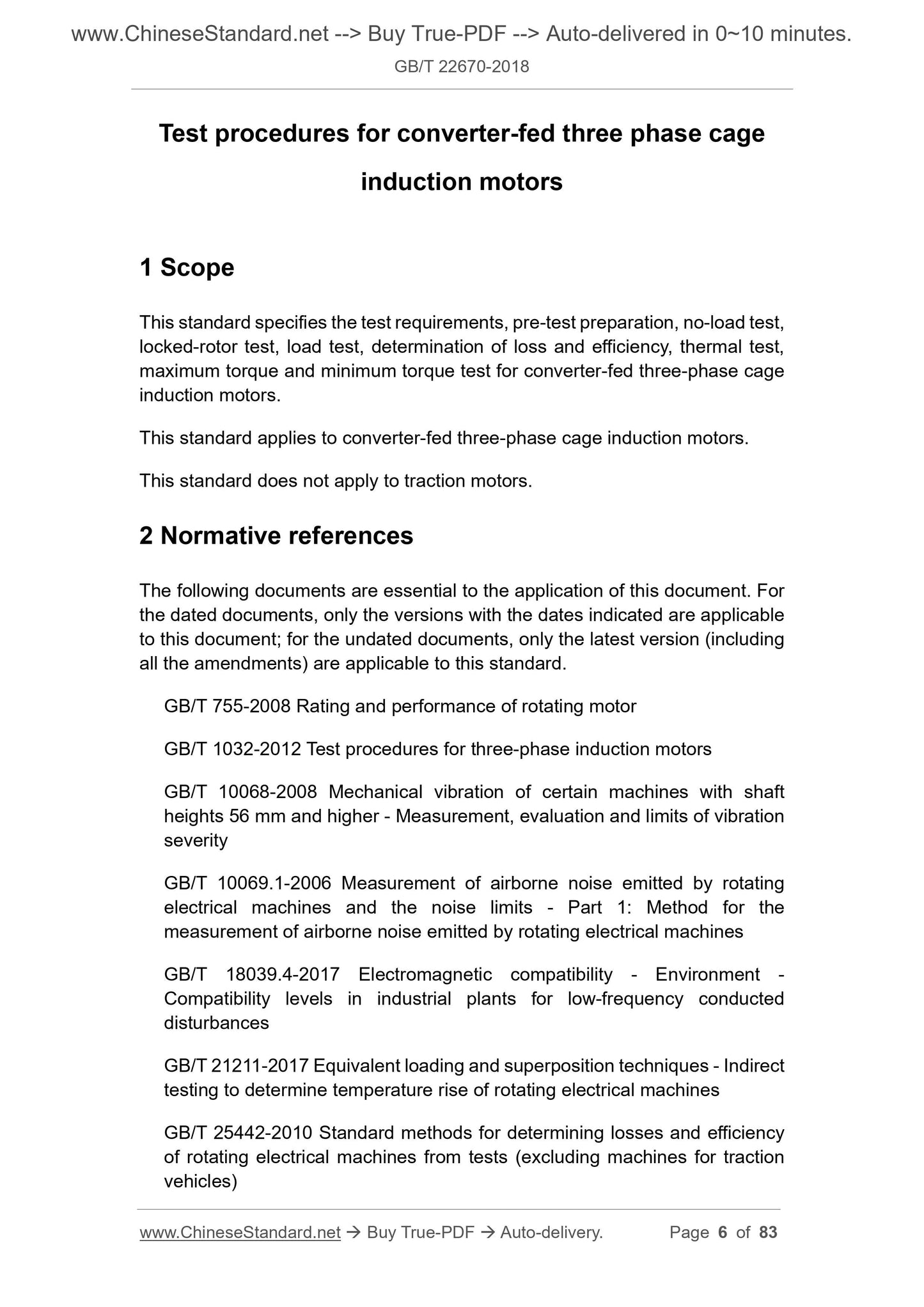
Test procedures for converter-fed three phase cage
induction motors
1 Scope
This standard specifies the test requirements, pre-test preparation, no-load test,
locked-rotor test, load test, determination of loss and efficiency, thermal test,
maximum torque and minimum torque test for converter-fed three-phase cage
induction motors.
This standard applies to converter-fed three-phase cage induction motors.
This standard does not apply to traction motors.
2 Normative references
The following documents are essential to the application of this document. For
the dated documents, only the versions with the dates indicated are applicable
to this document; for the undated documents, only the latest version (including
all the amendments) are applicable to this standard.
GB/T 755-2008 Rating and performance of rotating motor
GB/T 1032-2012 Test procedures for three-phase induction motors
GB/T 10068-2008 Mechanical vibration of certain machines with shaft
heights 56 mm and higher - Measurement, evaluation and limits of vibration
severity
GB/T 10069.1-2006 Measurement of airborne noise emitted by rotating
electrical machines and the noise limits - Part 1: Method for the
measurement of airborne noise emitted by rotating electrical machines
GB/T 18039.4-2017 Electromagnetic compatibility - Environment -
Compatibility levels in industrial plants for low-frequency conducted
disturbances
GB/T 21211-2017 Equivalent loading and superposition techniques - Indirect
testing to determine temperature rise of rotating electrical machines
GB/T 25442-2010 Standard methods for determining losses and efficiency
of rotating electrical machines from tests (excluding machines for traction
vehicles)
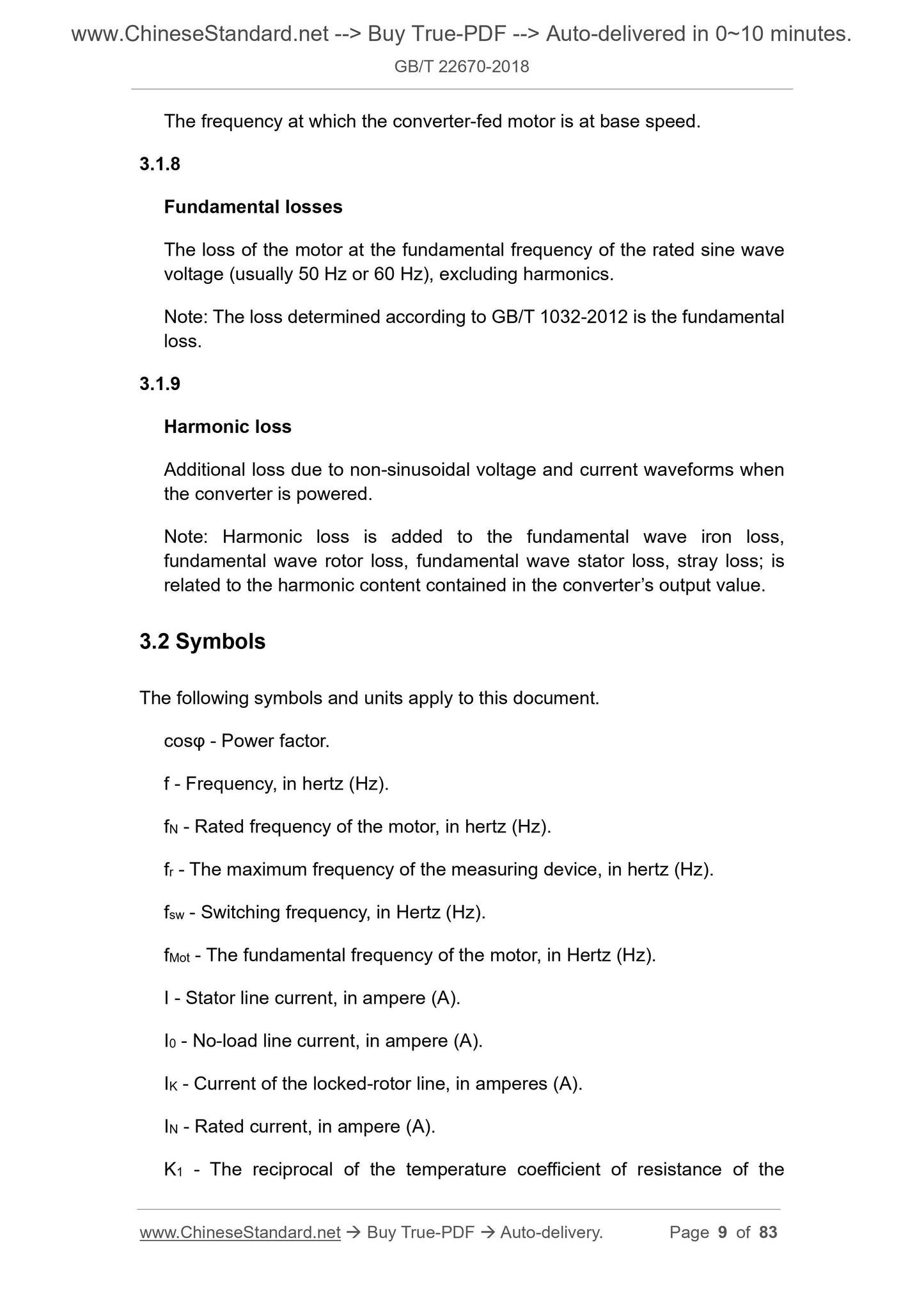
The frequency at which the converter-fed motor is at base speed.
3.1.8
Fundamental losses
The loss of the motor at the fundamental frequency of the rated sine wave
voltage (usually 50 Hz or 60 Hz), excluding harmonics.
Note: The loss determined according to GB/T 1032-2012 is the fundamental
loss.
3.1.9
Harmonic loss
Additional loss due to non-sinusoidal voltage and current waveforms when
the converter is powered.
Note: Harmonic loss is added to the fundamental wave iron loss,
fundamental wave rotor loss, fundamental wave stator loss, stray loss; is
related to the harmonic content contained in the converter’s output value.
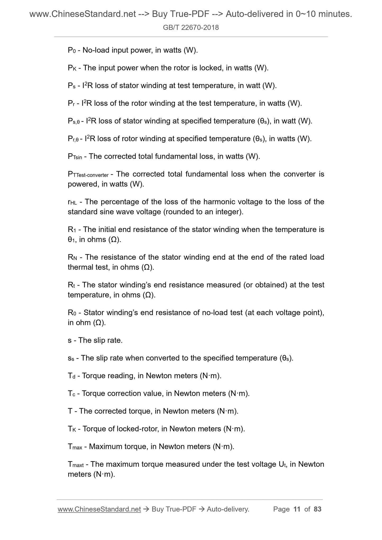
3.2 Symbols
The following symbols and units apply to this document.
cosφ - Power factor.
f - Frequency, in hertz (Hz).
fN - Rated frequency of the motor, in hertz (Hz).
fr - The maximum frequency of the measuring device, in hertz (Hz).
fsw - Switching frequency, in Hertz (Hz).
fMot - The fundamental frequency of the motor, in Hertz (Hz).
I - Stator line current, in ampere (A).
I0 - No-load line current, in ampere (A).
IK - Current of the locked-rotor line, in amperes (A).
IN - Rated current, in ampere (A).
K1 - The reciprocal of the temperature coefficient of resistance of the
P0 - No-load input power, in watts (W).
PK - The input power when the rotor is locked, in watts (W).
Ps - I2R loss of stator winding at test temperature, in watt (W).
Pr - I2R loss of the rotor winding at the test temperature, in watts (W).
Ps,θ - I2R loss of stator winding at specified temperature (θs), in watt (W).
Pr,θ - I2R loss of rotor winding at specified temperature (θs), in watts (W).
PTsin - The corrected total fundamental loss, in watts (W).
PTTest-converter - The corrected total fundamental loss when the converter is
powered, in watts (W).
rHL - The percentage of the loss of the harmonic voltage to the loss of the
standard sine wave voltage (rounded to an integer).
R1 - The initial end resistance of the stator winding when the temperature is
θ1, in ohms (Ω).
RN - The resistance of the stator winding end at the end of the rated load
thermal test, in ohms (Ω).
Rt - The stator winding’s end resistance measured (or obtained) at the test
temperature, in ohms (Ω).
R0 - Stator winding’s end resistance of no-load test (at each voltage point),
in ohm (Ω).
s - The slip rate.
ss - The slip rate when converted to the specified temperature (θs).
Td - Torque reading, in Newton meters (N·m).
Tc - Torque correction value, in Newton meters (N·m).
T - The corrected torque, in Newton meters (N·m).
TK - Torque of locked-rotor, in Newton meters (N·m).
Tmax - Maximum torque, in Newton meters (N·m).
Tmaxt - The maximum torque measured under the test voltage Ut, in Newton
meters (N·m).
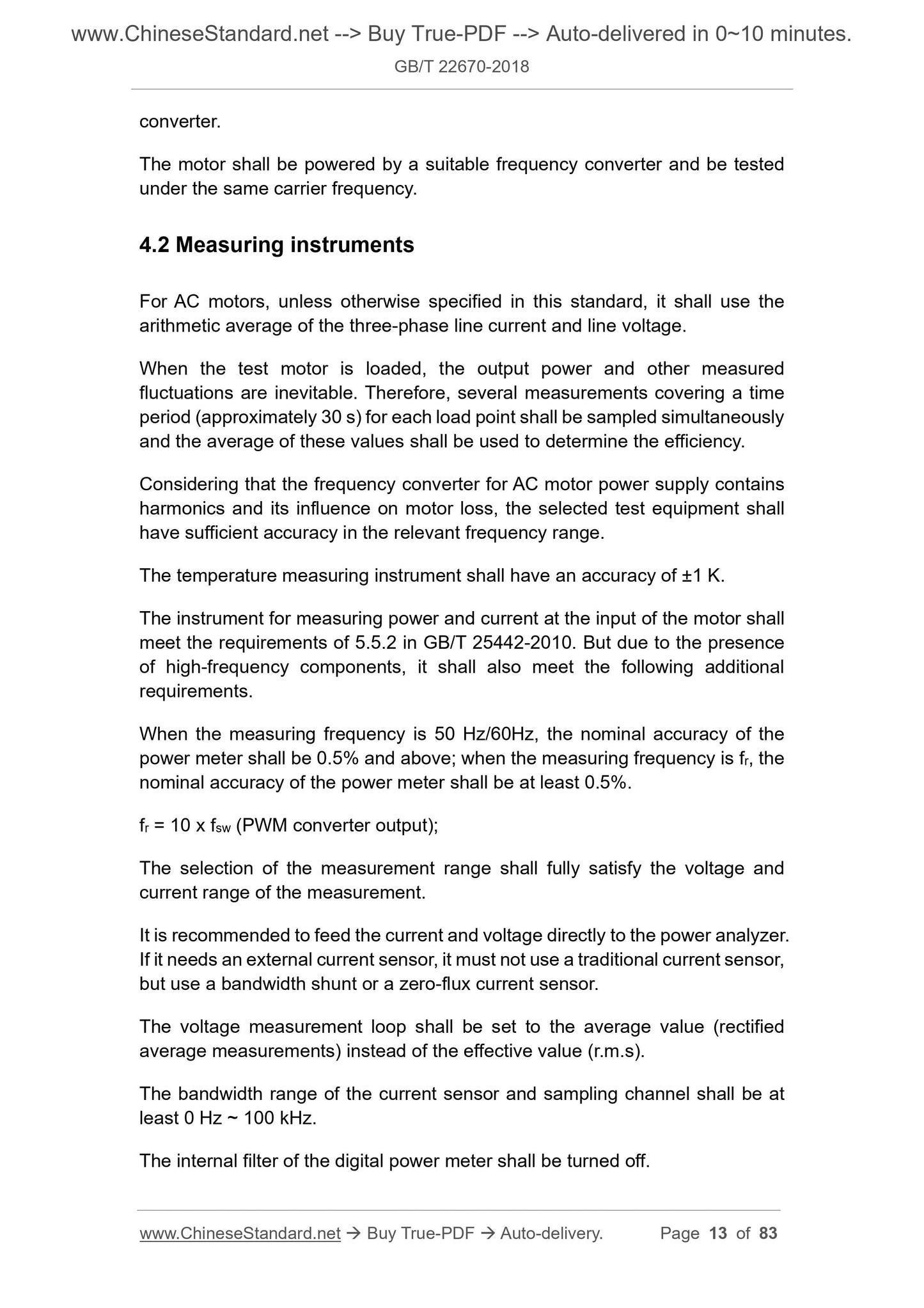
converter.
The motor shall be powered by a suitable frequency converter and be tested
under the same carrier frequency.
4.2 Measuring instruments
For AC motors, unless otherwise specified in this standard, it shall use the
arithmetic average of the three-phase line current and line voltage.
When the test motor is loaded, the output power and other measured
fluctuations are inevitable. Therefore, several measurements covering a time
period (approximately 30 s) for each load point shall be sampled simultaneously
and the average of these values shall be used to determine the efficiency.
Considering that the frequency converter for AC motor power supply contains
harmonics and its influence on motor loss, the selected test equipment shall
have sufficient accuracy in the relevant frequency range.
The temperature measuring instrument shall have an accuracy of ±1 K.
The instrument for measuring power and current at the input of the motor shall
meet the requirements of 5.5.2 in GB/T 25442-2010. But due to the presence
of high-frequency components, it shall also meet the following additional
requirements.
When the measuring frequency is 50 Hz/60Hz, the nominal accuracy of the
power meter shall be 0.5% and above; when the measuring frequency is fr, the
nominal accuracy of the power meter shall be at least 0.5%.
fr = 10 x fsw (PWM converter output);
The selection of the measurement range shall fully satisfy the voltage and
current range of the measurement.
It is recommended to feed the current and voltage directly to the power analyzer.
If it needs an external current sensor, it must not use a traditional current sensor,
but use a bandwidth shunt or a zero-flux current sensor.
The voltage measurement loop shall be set to the average value (rectified
average measurements) instead of the effective value (r.m.s).
The bandwidth range of the current sensor and sampling channel shall be at
least 0 Hz ~ 100 kHz.
The internal filter of the digital power meter shall be turned off.
output voltage or output current;
e) The fundamental wave voltage of the motor is equal to the rated voltage
UMot = UN (50 Hz or 60 Hz) of the motor at 50 Hz or 60 Hz; the input voltage
of the test converter shall be set to make the motor reach the allowable
rated voltage, meanwhile avoid overmodulation. At the same time, the
input voltage of the converter shall not be set too high, only need to reach
the output rated value;
f) The fundamental frequency of the motor is equal to the rated frequency of
the motor fMot = fN (50 Hz, 60 Hz);
g) When the rated output power is 90 kW and below, adjust the switching
frequency fsw to 4 kHz;
h) When the rated output power is above 90 kW, adjust the switching
frequency fsw to 2 kHz.
This standard defines the output level of the test converter and establishes a
test method to verify its suitability. The input of the test converter can be a
suitable AC or DC power supply.
Shielded cables shall be used to connect the test converter and the motor. The
cable length shall be less than 100 m; the cable size shall be selected according
to the motor power.
4.3.3 Test with frequency converter of terminal equipment
When the rated voltage of the converter is higher than 1 kV, the test converter
and cable length cannot be specified. At this time, the motor, cable and
converter can only be tested as a complete electric drive system, because the
pulse mode of the high-power converter varies from manufacturer to
manufacturer; meanwhile there is also a big difference in pulse mode under no-
load and rated load.
4.4 Measurement requirements
4.4.1 Voltage measurement
The signal wire of the measuring terminal voltage shall be connected to the
motor terminal. If this connection is not allowed on site, the error caused by this
shall be calculated and the reading shall be corrected. Take the arithmetic
average of the three-phase voltage to calculate the motor performance.
The symmetry of the three-phase voltage shall meet the requirements of 4.2.1.2
in GB/T 1032-2012.
θc - The temperature of the cooling medium at the entrance during the test,
in degrees Celsius (°C);
θw - Winding temperature determined in accordance with 5.4, in degrees
Celsius (°C).
For copper windings, the temperature constant is 235. For aluminum winding,
it is 225.
For motors that use water as the primary or secondary cooling medium, the
reference temperature of water is 25 °C according to Table 4 in GB/T 755-2008.
It can also be other values according to the agreement.
6 No-load test
6.1 Conditions for no-load test
No-load test refers to a test in which the motor runs as a no-load motor and its
shaft end has no effective mechanical power output.
Before reading and recording the test data, the input power of the motor shall
be stable, that is, the difference between two consecutive readings of the input
power 30 min apart shall not be greater than 3% of the previous reading.
For water-air cooling motors, it shall cut off the water source immediately after
the thermal test (or load test).
The no-load test shall be carried out in a hot state, that is, immediately after the
thermal test or the load test.
During the inspection test, the time of no-load operation can be appropriately
shortened.
6.2 Determine no-load current and no-load loss
The test shall test the following 8 voltage points, including the rated voltage
points, namely:
- Approximately 110%, 100%, 95%, 90% of the rated voltage shall be used
as the test voltage value t...
Share