Skip to product information
1 of 4

PayPal, credit cards. Download editable-PDF and invoice in 1 second!

YY/T 1705-2020 English PDF (YY/T1705-2020)

YY/T 1705-2020 English PDF (YY/T1705-2020)

Regular price $185.00 USD
Regular price Sale price $185.00 USD
Sale Sold out
Shipping calculated at checkout.
Delivery: 3 seconds. Download true-PDF + Invoice.
Get Quotation: Click YY/T 1705-2020 (Self-service in 1-minute)
Historical versions (Master-website): YY/T 1705-2020
Preview True-PDF (Reload/Scroll-down if blank)

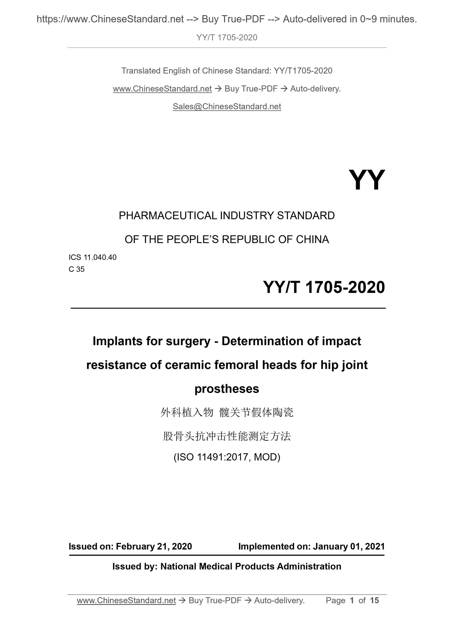
YY/T 1705-2020: Implants for surgery--Determination of impact resistance of ceramic femoral heads for hip joint prostheses
YY/T 1705-2020
Implants for surgery--Determination of impact resistance of ceramic femoral heads for hip joint prostheses
ICS 11.040.40
C35
People's Republic of China Pharmaceutical Industry Standard
Surgical implant hip joint prosthesis ceramics
Method for measuring impact resistance of femoral head
2020-02-21 released
2021-01-01 implementation
Issued by the State Drug Administration
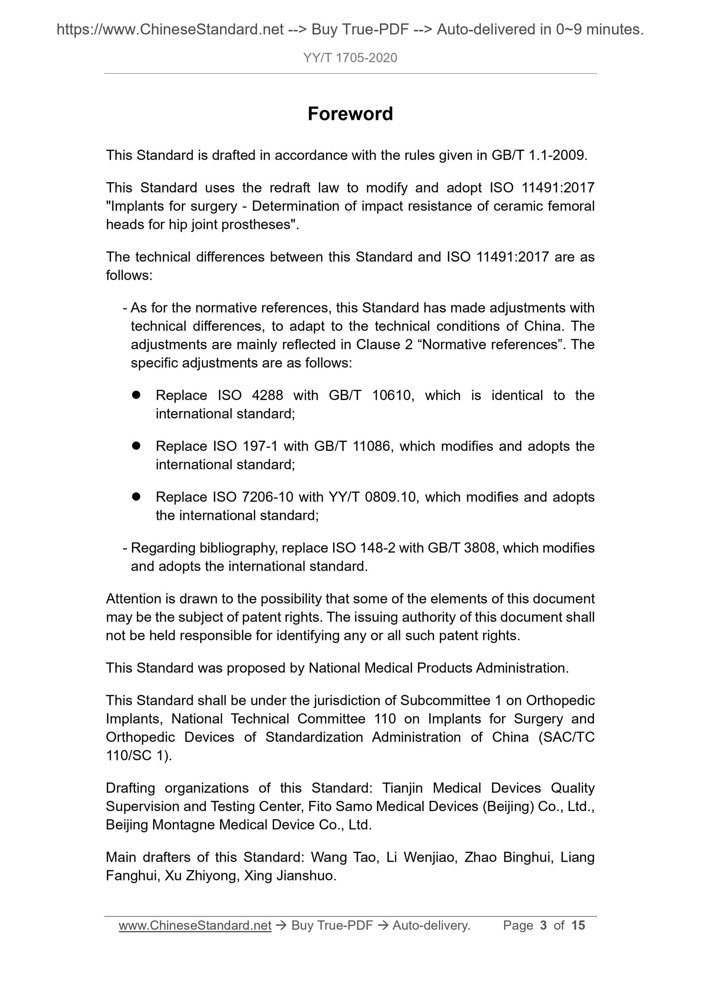
Preface
This standard was drafted in accordance with the rules given in GB/T 1.1-2009.
This standard uses the redrafting method to amend and adopt ISO 11491.2017 ``Impact resistance of ceramic femoral head of surgical implant hip joint prosthesis
Compilation of "Methods of Energy Measurement"
The technical differences between this standard and ISO 11491.2017 are as follows.
---Regarding normative reference documents, this standard has made adjustments with technical differences to adapt to my country's technical conditions and adjustments.
The situation is collectively reflected in Chapter 2 "Normative Reference Documents", and the specific adjustments are as follows.
● Replace ISO 4288 with GB/T 10610 which is equivalent to adopting international standards;
● Replace ISO 197-1 with GB/T 11086 modified to adopt international standards;
● Replace ISO 7206-10 with YY/T 0809.10 which is modified to adopt international standards;
--- Regarding references, ISO 148-2 is replaced by GB/T 3808 which is modified to adopt international standards.
Please note that certain contents of this document may involve patents. The issuing agency of this document is not responsible for identifying these patents.
This standard was proposed by the State Drug Administration.
This standard is organized by the Orthopedic Implants Sub-Technical Committee of the National Standardization Technical Committee for Surgical Implants and Orthopedic Devices (SAC/TC110/
SC1) Centralized.
Drafting organizations of this standard. Tianjin Medical Device Quality Supervision and Inspection Center, Feidu Satsuma Medical Devices (Beijing) Co., Ltd., Beijing Mongolia
Taiyin Medical Devices Co., Ltd.
The main drafters of this standard. Wang Tao, Li Wenjiao, Zhao Binghui, Liang Fanghui, Xu Zhiyong, Xing Jianshuo.
introduction
Partial and total hip prostheses are designed to transfer loads and be able to move under high stress conditions. They are expected to replace anatomical structures and provide the best
Can approach the characteristics of normal natural joints. Some total hip prosthesis femoral components consist of ceramic femoral heads and metal femoral stems. So using
In use, it is very important that the ceramic femoral head has sufficient strength to withstand the static load and possible dynamic impact load imposed on the prosthesis. research
The study found that the rupture of the zirconia femoral head in the test of YY/T 0809.10 is different from the clinical fracture of the femoral head, while the alumina femoral head
The rupture is similar to the rupture of the femoral head that occurs clinically. It is very important to understand the state of the sample after the impact load is applied, such as simple static crushing
The test may not detect delayed fracture, especially for new ceramic materials and/or new cone structures. Therefore, this standard specifies two
An alternative test method is used to determine the impact strength of ceramic femoral heads.
The fracture mechanism of the ceramic femoral head after an impact load may be the immediate breaking of the overload or the subcritical crack propagation. Subcritical crack expansion
The development may cause the product to fail when the force is lower than the initial static crushing load. The ceramic femoral head passes through the metal journal (femoral neck component) and the femoral
Loading at bone joints, subcritical crack propagation may be caused by impact or incremental quasi-static loading-unloading cycles.
Surgical implant hip joint prosthesis ceramics
Method for measuring impact resistance of femoral head
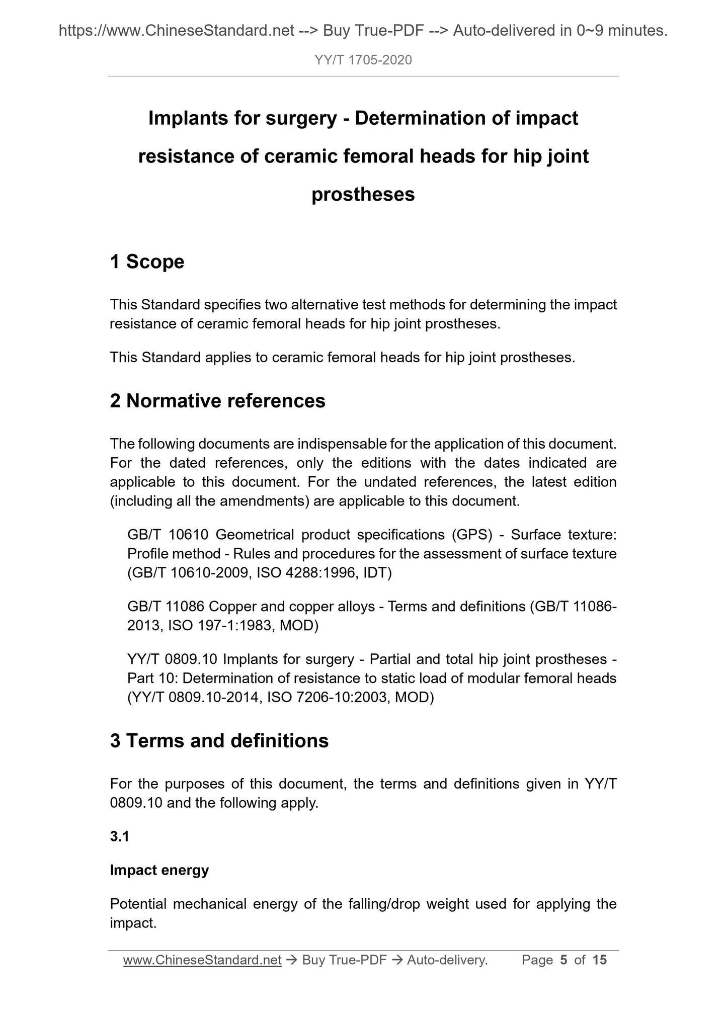
1 Scope
This standard specifies two alternative test methods for determining the impact resistance of ceramic femoral heads of hip joint prostheses.
This standard applies to ceramic femoral heads of hip prostheses.
2 Normative references
The following documents are indispensable for the application of this document. For dated reference documents, only the dated version applies to this article
Pieces. For undated references, the latest version (including all amendments) applies to this document.
GB/T 10610 Geometrical Technical Specifications for Products (GPS) Surface Structure Profile Method. Rules and Methods for Evaluating Surface Structure (GB/T
10610-2009, ISO 4288.1996, IDT)
GB/T 11086 Terminology for copper and copper alloys (GB/T 11086-2013, ISO 197-1.1983, MOD)
YY/T 0809.10 Surgical implant parts and total hip joint prostheses. Part 10.Determination of the static resistance of the combined femoral head
(YY/T 0809.10-2014,ISO 7206-10.2003,MOD)
3 Terms and definitions
The following terms and definitions defined in YY/T 0809.10 apply to this document.
3.1
Impact energy
The potential energy of the falling weight/falling weight used when the impact is applied.
3.2
Cycle impact resistance
When continuously increasing impact energy is applied, the maximum impact energy when the sample does not fail.
3.3
Impact load
The peak force measured before the sample breaks when the impact energy or quasi-static load-unload cycle is applied.
3.4
Impact velocity
The instantaneous velocity before the falling weight hits the test sample.
3.5
Quasi-static force
The force value changes slowly with time, so the influence of mass inertia can be ignored.
4 Principle
This standard can be used for material development, material comparison, quality assurance, implant system performance characterization, reliability analysis and design data generation.
It is determined by applying an increasing energy impact to the femoral head/cone connection assembly and identifying the maximum impact energy that prevents the femoral head from rupturing
Cycle impact resistance. Or, through a quasi-static force loading-unloading cycle test, and identifying the maximum load that prevents the femoral head from rupturing
Determine the impact load (cyclic strength).
Note. These test methods are most suitable for comparison with the ceramic femoral head and metal femoral stem cone connection systems that have been established and verified clinically.
Evaluate the new ceramic femoral head material combined with the metal shank cone connection and the new cone connection design.
5 Equipment
5.1 Impact testing machine
The testing machine should have a rigid structure and be able to apply an impact to the test sample through a drop hammer. The testing machine should be stably installed on the ground or heavy and hard
On the workbench (such as. granite or steel top test bench). The testing machine should include a drop weight component with adjustable mass.
Such height can adjust the application range of impact energy. The drop hammer can have a guide rail or be a free fall. The guide rail should minimize friction. The rail should not be
Impact component contact. The test sample composed of femoral head and femoral neck components can be placed on the support block, which is installed on the pressure sensor
surface. The different components of the falling weight, test sample, support block and pressure sensor should be axially and vertically aligned, with an angle deviation of ±1°, and a lateral deviation of
±1mm. The tooling for placing the test sample should have a small mass, but should have sufficient stiffness and strength to withstand multiple shocks.
An example of the test machine is shown in Figure 1.
In order to prevent the sample/femoral neck component from dislocation when an impact load is applied, a linear bearing or low friction should be installed on the femoral neck component support
casing. The device prevents accidental movement of the sample/femoral neck component after impact. Impact plate (femoral neck component support) as a drop hammer
The impact target should have appropriate stiffness, diameter and thickness, but should be as small as possible within the allowable range.
5.2 Impact test device
5.2.1 Drop hammer
The impact energy can be calculated from the total mass of all parts of the falling weight device. The impact energy is calculated by measuring the mass of the falling hammer and the height of the drop, which is not correct
The rating should be within ±2%.
If the impact energy is calculated by the potential energy of the falling hammer, the kinetic energy during the impact of the falling hammer should be checked regularly by measuring the impact velocity. kinetic energy
The uncertainty of calculation of any deviation from the potential energy should be within ±2%.
In order to reduce the frictional resistance between the drop weight and the guide rail, the drop weight device should be equipped with linear bearings or low friction sleeves.
Refer to GB/T 3808 for inspection principle or cycle.
5.2.2 Femoral neck components
The femoral neck component is matched with the cone hole of the ceramic femoral head, and should be made of the same material as the hip joint prosthesis component (femoral stem), and has
The same outer cone size, including shape and surface requirements, and using the same manufacturing process, should have a shape suitable for the testing machine.
A new femoral neck component was used for each trial. There should be no foreign body in the conical joint of the femoral neck component that is in contact with the ceramic femoral head.
5.2.3 Support fixture
5.2.3.1 Support block
The support block is made of steel, and its size and hardness should meet the requirements of YY/T 0809.10.The support block should be installed on the abutment through the base.
Note. Usually the diameter of the support block is about 2 times the diameter of the measured femoral head, and the height is 1.0 to 1.5 times the diameter of the femoral head.
5.2.3.2 Copper ring
The copper ring should have a shape matching the diameter of the test sample according to the requirements of YY/T 0809.10, with a tolerance of ±0.1mm. From refined copper
The minimum copper content is 99.85% (mass fraction) according to GB/T 11086.A new copper ring should be used for each test sample.
5.2.4 Pressure sensor and data logger
5.2.4.1 General
By measuring and recording the force generated by the impact, the force on the test sample and any abnormal conditions in the test can be monitored.
5.2.4.2 Pressure sensor
The pressure sensor is an impact load sensor (non-static) and should be firmly installed in accordance with the manufacturer's specifications.
5.2.4.3 Pressure sensor data logger
The sampling frequency of the data logger is at least.200kHz, and it should be able to record impact load data at least 500ms after the impact.
5.2.5 Base and abutment
The base and abutment should be made of steel, strong enough to support the test device.
5.3 Testing machine, device and setting for cyclic loading-unloading crushing test
The testing machine, device and test setup shall meet the requirements of static compression test in YY/T 0809.10.The test requires load control.
Therefore, the testing machine should be able to perform compression tests through load control.
5.4 Test sample
5.4.1 Geometric accuracy and specifications
Commercial ceramic femoral head products or products with the same design, material and processing technology as expected
Test samples.
If the ceramic femoral head has a series of diameters, matching lengths, etc., if the product supplier has no special requirements, the "worst case" specifications should be used.
Product for testing.
5.4.2 Number of samples
For each product design and/or material combination, at least 5 sets of samples are tested.
6 steps
6.1 General
6.1.1 Organic solvents and neutral detergents should be used to clean the copper ring to remove oils, lipids and pollutants.
6.1.2 Each test uses a new ceramic femoral head and femoral neck components, cleaned in accordance with the method specified in YY/T 0809.10.
6.1.3 Use a new copper ring load uniforming device for each test. Each test sample (femoral head) uses a copper ring until the end of the test.
Note. It is reported that the contaminants contained in the connection part of the ceramic femoral head conical hole and the outer cone of the femoral stem will significantly reduce the mechanical strength of the ceramic femoral head.
6.1.4 Install the ceramic femoral head on the femoral neck component. Care should be taken to keep the femoral neck component and the ceramic femoral head on the same axis.
Note. When the test sample is installed on the femoral neck component, rotating the test sample helps to make the femoral neck component and the sample on the same axis.
6.1.5 Apply the installation load in accordance with the method specified in YY/T 0809.10.If the sample is damaged for any reason, it must not be used for testing.
6.2 Impact resistance test method (cycle strength)
6.2.1 Place the test sample
Place the sample/femoral neck component in the testing machine tooling. Adjust the loading shafts of different parts to vertical alignment, the angle deviation is
±1°, and adjust the horizontal center position, the deviation is ±1mm. When placing the test sample, care should be taken to avoid applying impact to it.
6.2.2 Applying an impact
With an appropriate drop weight (m) and 1m drop height (H), an initial impact energy of 20J is applied to the sample. Make sure the femoral head is in the thigh
The bone neck components are correctly assembled, and the copper ring is deformed to match the shape of the femoral head and the supporting block.
In the case that the sample does not break, the impact energy is increased on the basis of the initial impact energy.
Increase the weight of the falling weight to increase the impact energy by 10J.
In the impact test, check and correct the position of the copper ring and the loading shaft of the test sample. At least 1h between two impacts. Keep experimenting,
Until the femoral head appears cracked or broken.
If the interval between two impacts is short, the test report should state its rationality. ...
View full details