Skip to product information
1 of 10

PayPal, credit cards. Download editable-PDF and invoice in 1 second!

YY/T 1028-2023 English PDF (YYT1028-2023)

YY/T 1028-2023 English PDF (YYT1028-2023)

Regular price $245.00 USD
Regular price Sale price $245.00 USD
Sale Sold out
Shipping calculated at checkout.
Delivery: 3 seconds (Download full-editable-PDF + Invoice).
Quotation: Click YY/T 1028-2023>>Add to cart>>Quote
Editable-PDF Preview (Reload if blank, scroll for next page)

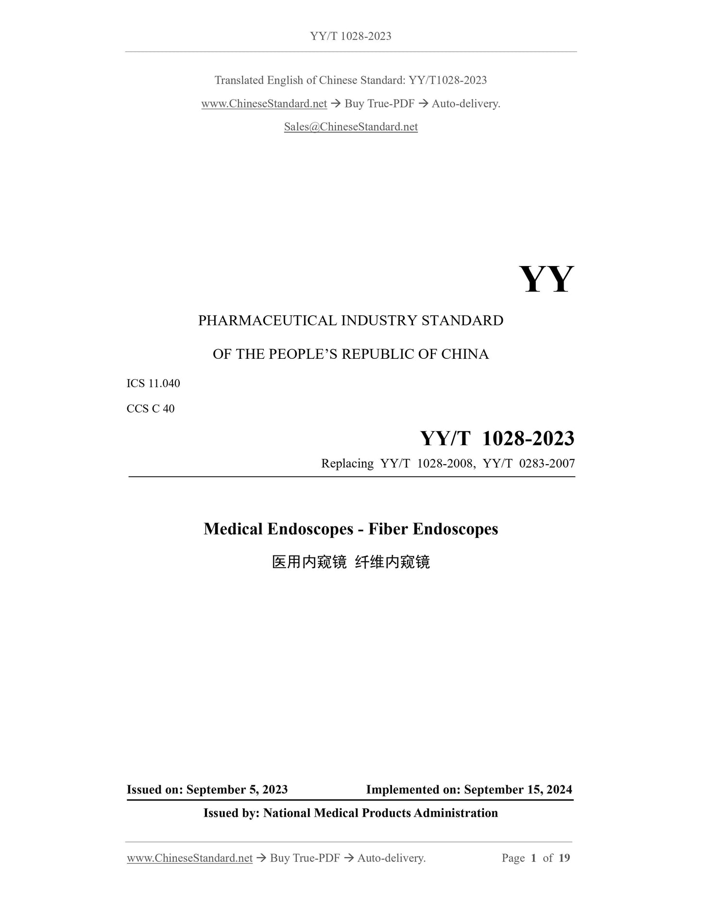
YY/T 1028-2023: Medical endoscopes - Fiber endoscopes
This document specifies the requirements for medical fiber endoscopes and describes the corresponding test methods. This document is applicable to medical fiber endoscopes.
YY/T 1028-2023
YY
PHARMACEUTICAL INDUSTRY STANDARD
OF THE PEOPLE’S REPUBLIC OF CHINA
ICS 11.040
CCS C 40
Replacing YY/T 1028-2008, YY/T 0283-2007
Medical Endoscopes - Fiber Endoscopes
ISSUED ON: SEPTEMBER 5, 2023
IMPLEMENTED ON: SEPTEMBER 15, 2024
Issued by: National Medical Products Administration
Table of Contents
Foreword ... 3
1 Scope ... 5
2 Normative References ... 5
3 Terms and Definitions ... 5
4 Requirements ... 6
5 Test Methods ... 11
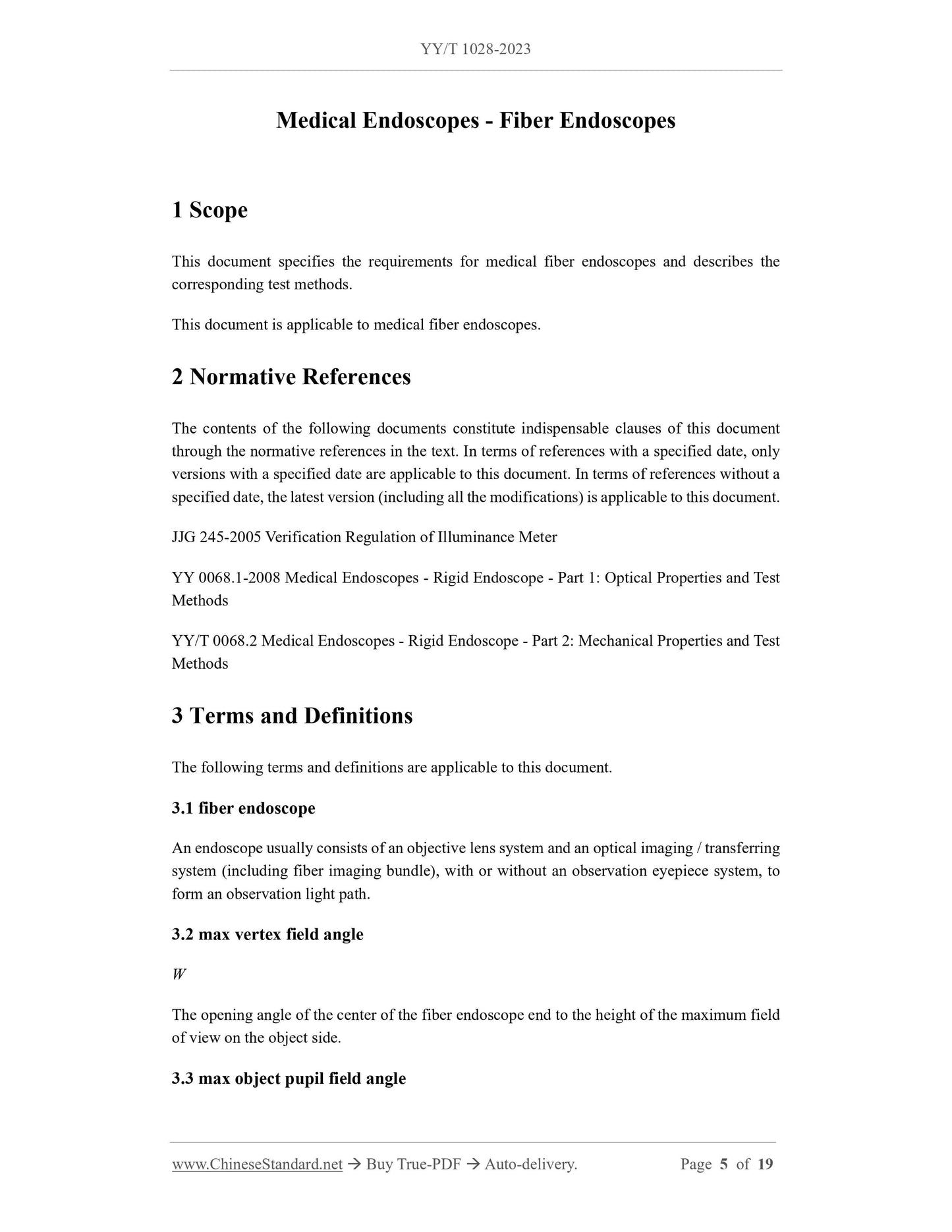
Medical Endoscopes - Fiber Endoscopes
1 Scope
This document specifies the requirements for medical fiber endoscopes and describes the corresponding test methods.
This document is applicable to medical fiber endoscopes.
2 Normative References
The contents of the following documents constitute indispensable clauses of this document through the normative references in the text. In terms of references with a specified date, only versions with a specified date are applicable to this document. In terms of references without a specified date, the latest version (including all the modifications) is applicable to this document. JJG 245-2005 Verification Regulation of Illuminance Meter
YY 0068.1-2008 Medical Endoscopes - Rigid Endoscope - Part 1: Optical Properties and Test Methods
YY/T 0068.2 Medical Endoscopes - Rigid Endoscope - Part 2: Mechanical Properties and Test Methods
3 Terms and Definitions
The following terms and definitions are applicable to this document.
3.1 fiber endoscope
An endoscope usually consists of an objective lens system and an optical imaging / transferring system (including fiber imaging bundle), with or without an observation eyepiece system, to form an observation light path.
3.2 max vertex field angle
The opening angle of the center of the fiber endoscope end to the height of the maximum field of view on the object side.
3.3 max object pupil field angle
Wp
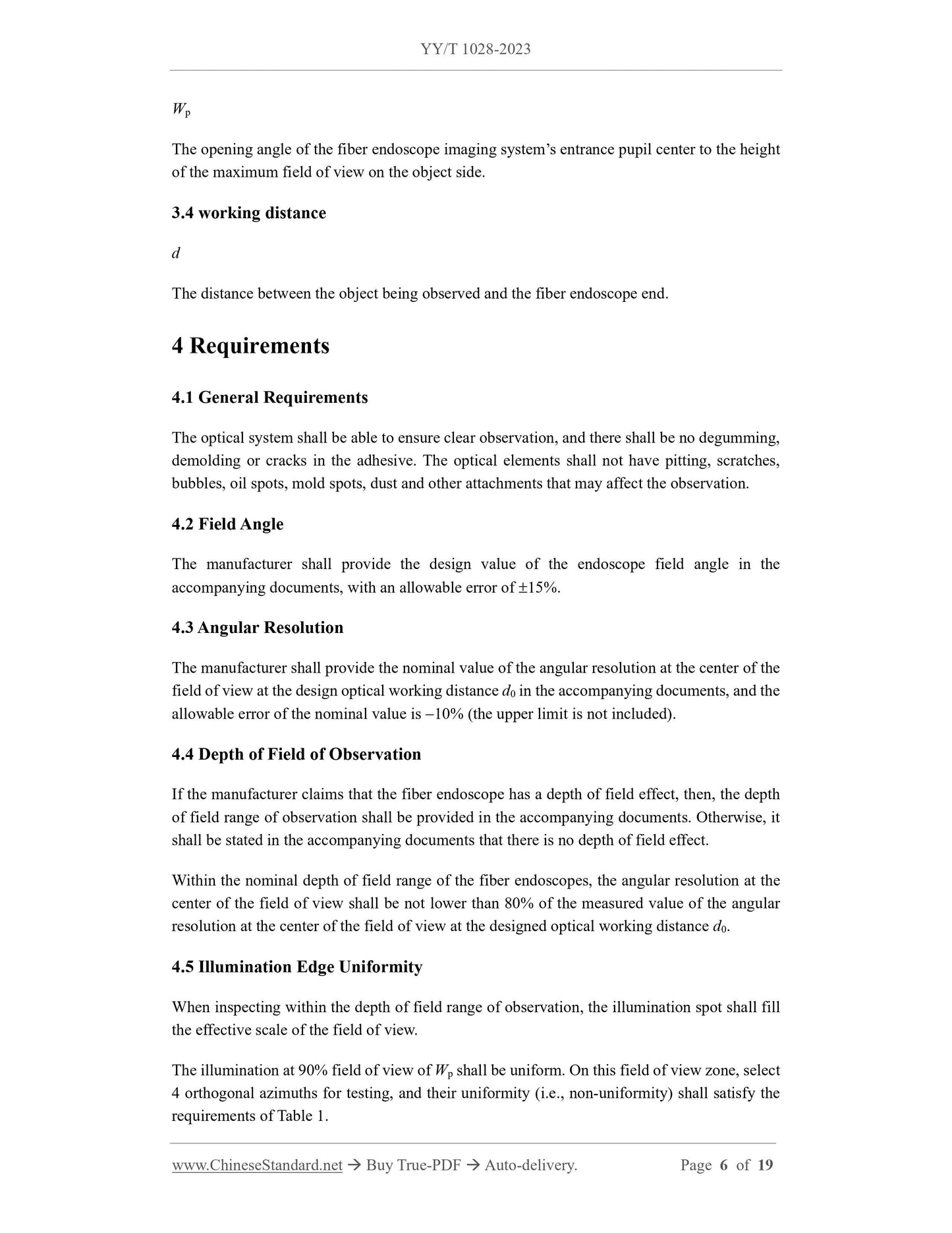
The opening angle of the fiber endoscope imaging system’s entrance pupil center to the height of the maximum field of view on the object side.
3.4 working distance
The distance between the object being observed and the fiber endoscope end. 4 Requirements
4.1 General Requirements
The optical system shall be able to ensure clear observation, and there shall be no degumming, demolding or cracks in the adhesive. The optical elements shall not have pitting, scratches, bubbles, oil spots, mold spots, dust and other attachments that may affect the observation. 4.2 Field Angle
The manufacturer shall provide the design value of the endoscope field angle in the accompanying documents, with an allowable error of 15%.
4.3 Angular Resolution
The manufacturer shall provide the nominal value of the angular resolution at the center of the field of view at the design optical working distance d0 in the accompanying documents, and the allowable error of the nominal value is 10% (the upper limit is not included). 4.4 Depth of Field of Observation
If the manufacturer claims that the fiber endoscope has a depth of field effect, then, the depth of field range of observation shall be provided in the accompanying documents. Otherwise, it shall be stated in the accompanying documents that there is no depth of field effect. Within the nominal depth of field range of the fiber endoscopes, the angular resolution at the center of the field of view shall be not lower than 80% of the measured value of the angular resolution at the center of the field of view at the designed optical working distance d0. 4.5 Illumination Edge Uniformity
When inspecting within the depth of field range of observation, the illumination spot shall fill the effective scale of the field of view.
The illumination at 90% field of view of Wp shall be uniform. On this field of view zone, select 4 orthogonal azimuths for testing, and their uniformity (i.e., non-uniformity) shall satisfy the requirements of Table 1.
and comfortable.
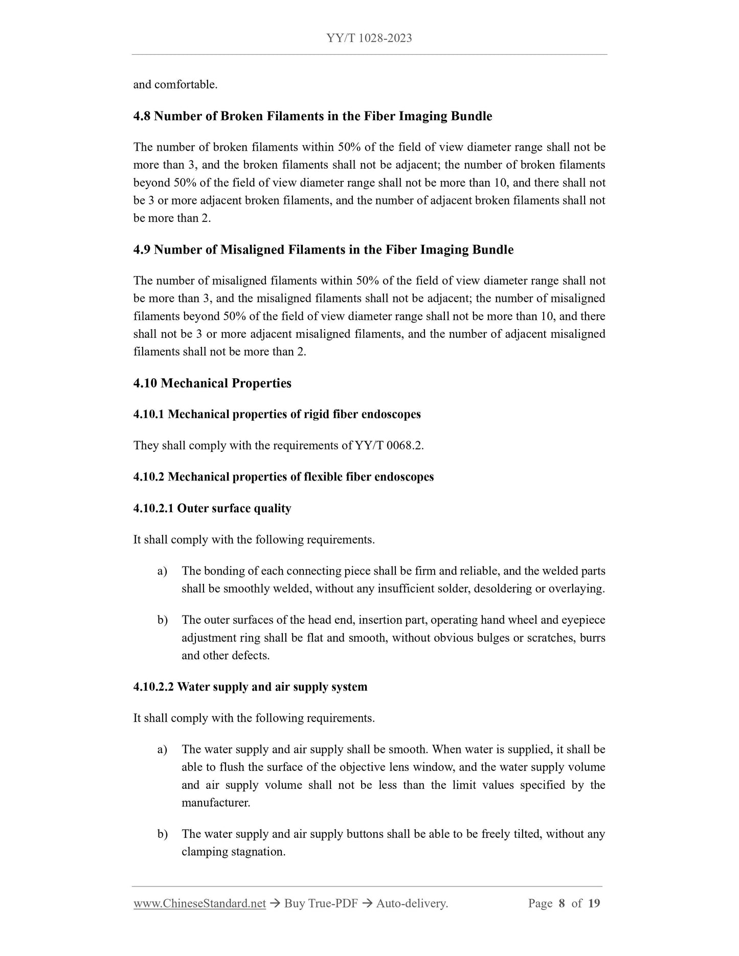
4.8 Number of Broken Filaments in the Fiber Imaging Bundle
The number of broken filaments within 50% of the field of view diameter range shall not be more than 3, and the broken filaments shall not be adjacent; the number of broken filaments beyond 50% of the field of view diameter range shall not be more than 10, and there shall not be 3 or more adjacent broken filaments, and the number of adjacent broken filaments shall not be more than 2.
4.9 Number of Misaligned Filaments in the Fiber Imaging Bundle
The number of misaligned filaments within 50% of the field of view diameter range shall not be more than 3, and the misaligned filaments shall not be adjacent; the number of misaligned filaments beyond 50% of the field of view diameter range shall not be more than 10, and there shall not be 3 or more adjacent misaligned filaments, and the number of adjacent misaligned filaments shall not be more than 2.
4.10 Mechanical Properties
4.10.1 Mechanical properties of rigid fiber endoscopes
They shall comply with the requirements of YY/T 0068.2.
4.10.2 Mechanical properties of flexible fiber endoscopes
4.10.2.1 Outer surface quality
It shall comply with the following requirements.
a) The bonding of each connecting piece shall be firm and reliable, and the welded parts shall be smoothly welded, without any insufficient solder, desoldering or overlaying. b) The outer surfaces of the head end, insertion part, operating hand wheel and eyepiece adjustment ring shall be flat and smooth, without obvious bulges or scratches, burrs and other defects.
4.10.2.2 Water supply and air supply system
It shall comply with the following requirements.
a) The water supply and air supply shall be smooth. When water is supplied, it shall be able to flush the surface of the objective lens window, and the water supply volume and air supply volume shall not be less than the limit values specified by the manufacturer.
b) The water supply and air supply buttons shall be able to be freely tilted, without any clamping stagnation.
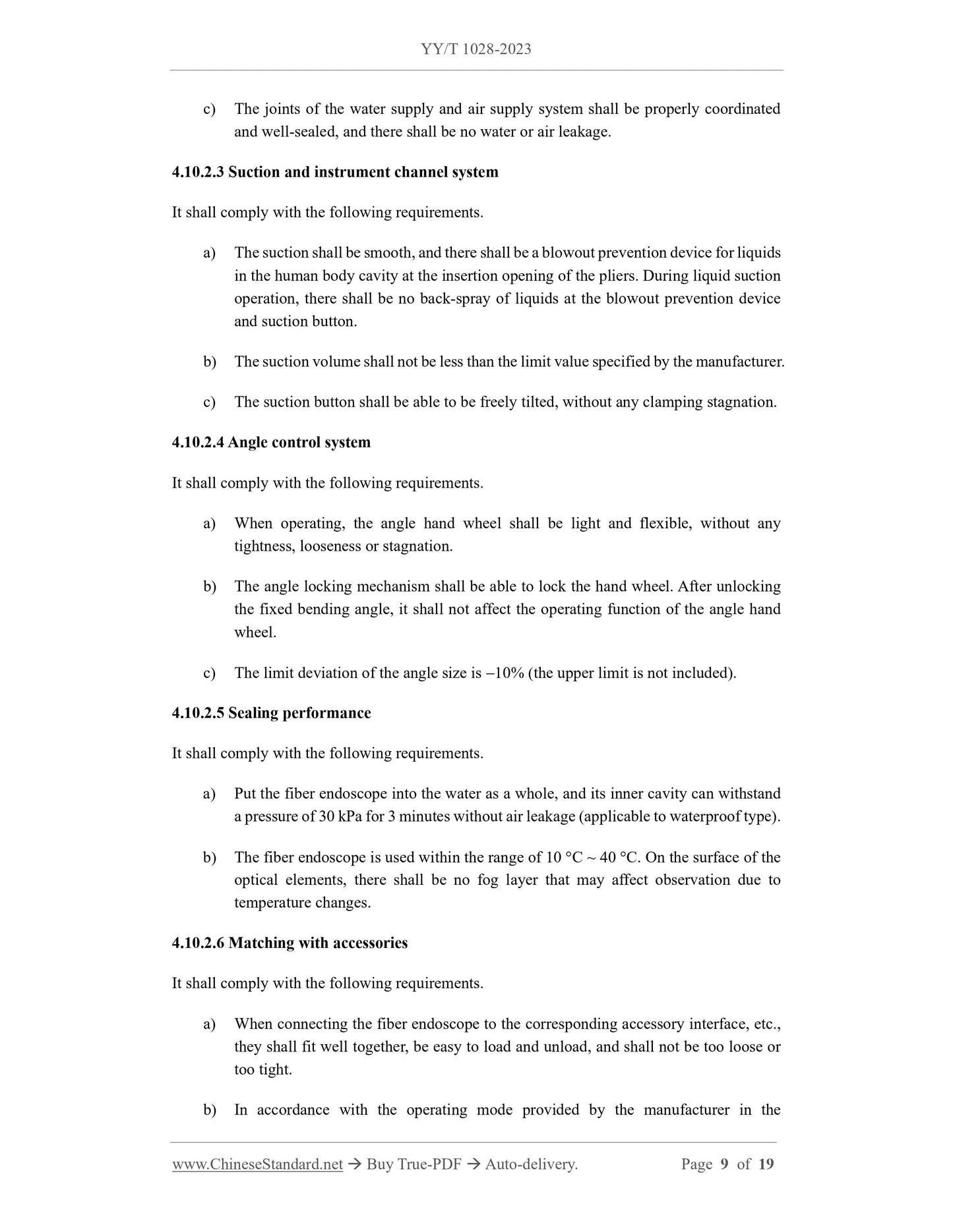
c) The joints of the water supply and air supply system shall be properly coordinated and well-sealed, and there shall be no water or air leakage.
4.10.2.3 Suction and instrument channel system
It shall comply with the following requirements.
a) The suction shall be smooth, and there shall be a blowout prevention device for liquids in the human body cavity at the insertion opening of the pliers. During liquid suction operation, there shall be no back-spray of liquids at the blowout prevention device and suction button.
b) The suction volume shall not be less than the limit value specified by the manufacturer. c) The suction button shall be able to be freely tilted, without any clamping stagnation. 4.10.2.4 Angle control system
It shall comply with the following requirements.
a) When operating, the angle hand wheel shall be light and flexible, without any tightness, looseness or stagnation.
b) The angle locking mechanism shall be able to lock the hand wheel. After unlocking the fixed bending angle, it shall not affect the operating function of the angle hand wheel.
c) The limit deviation of the angle size is 10% (the upper limit is not included). 4.10.2.5 Sealing performance
It shall comply with the following requirements.
a) Put the fiber endoscope into the water as a whole, and its inner cavity can withstand a pressure of 30 kPa for 3 minutes without air leakage (applicable to waterproof type). b) The fiber endoscope is used within the range of 10 C ~ 40 C. On the surface of the optical elements, there shall be no fog layer that may affect observation due to temperature changes.
4.10.2.6 Matching with accessories
It shall comply with the following requirements.
a) When connecting the fiber endoscope to the corresponding accessory interface, etc., they shall fit well together, be easy to load and unload, and shall not be too loose or too tight.
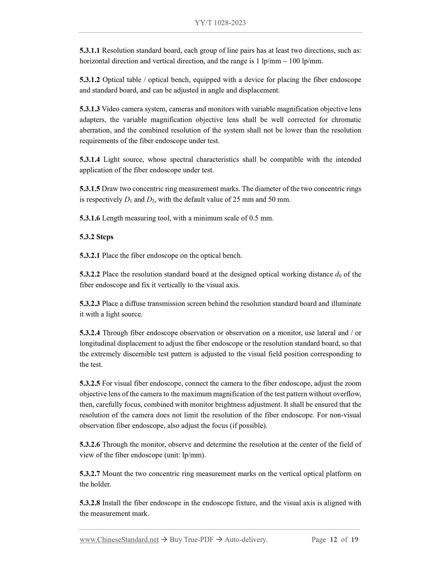
b) In accordance with the operating mode provided by the manufacturer in the 5.3.1.1 Resolution standard board, each group of line pairs has at least two directions, such as: horizontal direction and vertical direction, and the range is 1 lp/mm ~ 100 lp/mm. 5.3.1.2 Optical table / optical bench, equipped with a device for placing the fiber endoscope and standard board, and can be adjusted in angle and displacement.
5.3.1.3 Video camera system, cameras and monitors with variable magnification objective lens adapters, the variable magnification objective lens shall be well corrected for chromatic aberration, and the combined resolution of the system shall not be lower than the resolution requirements of the fiber endoscope under test.
5.3.1.4 Light source, whose spectral characteristics shall be compatible with the intended application of the fiber endoscope under test.
5.3.1.5 Draw two concentric ring measurement marks. The diameter of the two concentric rings is respectively D1 and D2, with the default value of 25 mm and 50 mm.
5.3.1.6 Length measuring tool, with a minimum scale of 0.5 mm.
5.3.2 Steps
5.3.2.1 Place the fiber endoscope on the optical bench.
5.3.2.2 Place the resolution standard board at the designed optical working distance d0 of the fiber endoscope and fix it vertically to the visual axis.
5.3.2.3 Place a diffuse transmission screen behind the resolution standard board and illuminate it with a light source.
5.3.2.4 Through fiber endoscope observation or observation on a monitor, use lateral and / or longitudinal displacement to adjust the fiber endoscope or the resolution standard board, so that the extremely discernible test pattern is adjusted to the visual field position corresponding to the test.
5.3.2.5 For visual fiber endoscope, connect the camera to the fiber endoscope, adjust the zoom objective lens of the camera to the maximum magnification of the test pattern without overflow, then, carefully focus, combined with monitor brightness adjustment. It shall be ensured that the resolution of the camera does not limit the resolution of the fiber endoscope. For non-visual observation fiber endoscope, also adjust the focus (if possible).
5.3.2.6 Through the monitor, observe and determine the resolution at the center of the field of view of the fiber endoscope (unit: lp/mm).
5.3.2.7 Mount the two concentric ring measurement marks on the vertical optical platform on the holder.
5.3.2.8 Install the fiber endoscope in the endoscope fixture, and the visual axis is aligned with the measurement mark.
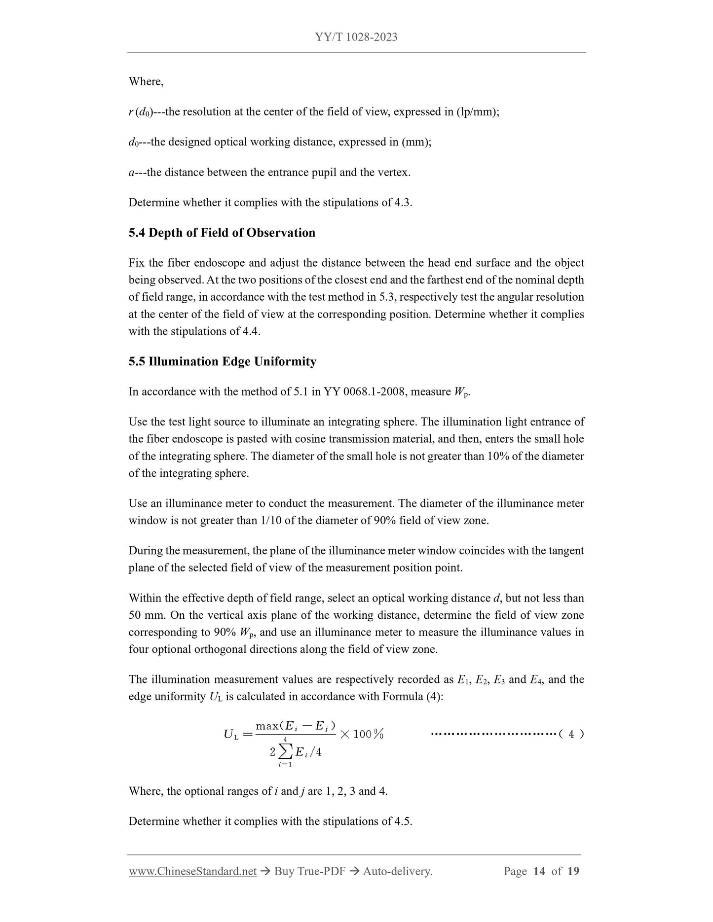
Where,
r (d0)---the resolution at the center of the field of view, expressed in (lp/mm); d0---the designed optical working distance, expressed in (mm);
a---the distance between the entrance pupil and the vertex.
Determine whether it complies with the stipulations of 4.3.
5.4 Depth of Field of Observation
Fix the fiber endoscope and adjust the distance between the head end surface and the object being observed. At the two positions of the closest end and the farthest end of the nominal depth of field range, in accordance with the test method in 5.3, respectively test the angular resolution at the center of the field of view at the corresponding position. Determine whether it complies with the stipulations of 4.4.
5.5 Illumination Edge Uniformity
In accordance with the method of 5.1 in YY 0068.1-2008, measure Wp.
Use the test light source to illuminate an integrating sphere. The illumination light entrance of the fiber endoscope is pasted with cosine transmission material, and then, enters the small hole of the integrating sphere. The diameter of the small hole is not greater than 10% of the diameter of the integrating sphere.
Use an illuminance meter to conduct the measurement. The diameter of the illuminance meter window is not greater than 1/10 of the diameter of 90% field of view zone. During the measurement, the plane of the illuminance meter window coincides with the tangent plane of the selected field of view of the measurement position point.
Within the effective depth of field range, select an optical working distance d, but not less than 50 mm. On the vertical axis plane of the working distance, determine the field of view zone corresponding to 90% Wp, and use an illuminance meter to measure the illuminance values in four optional orthogonal directions along the field of view zone.
The illumination measurement values are respectively recorded as E1, E2, E3 and E4, and the edge uniformity UL is calculated in accordance with Formula (4):
Where, the optional ranges of i and j are 1, 2, 3 and 4.
Determine whether it complies with the stipulations of 4.5.
5.6 Light Energy Transfer Efficiency---Effective Photometric Rate
5.6.1 Equipment
5.6.1.1 Bracket and platform, which are used for supporting the fiber endoscopes. 5.6.1.2 Cosine radiation screen. An illumination source with adjustable light intensity is enclosed on the back of the screen, and its spectral characteristics shall be compatible with the intended application of the fiber endoscope under test. The brightness of the screen is consistent, and the unevenness is not greater than 5%. Except the screen surface, this radiation screen has no other light leakage.
5.6.1.3 Illuminance meter. Use a secondary illuminance meter that complies with the stipulations of JJG 245-2005.
5.6.1.4 Luminous flux meter or equivalent device, with an accuracy level equivalent to that of an illuminance meter.
5.6.1.5 Reticle, with a minimum scale not greater than 0.5 mm.
5.6.1.6 Micrometer telescope, whose field angle is greater than the exit pupil field angle of the fiber endoscope under test.
5.6.2 Environmental conditions
5.6.2.1 The test environment is controlled so that the dark illumination is not greater than 1 lx. 5.6.2.2 The volage of the light source power supply shall maintain stable at the nominal voltage value, and the voltage stability shall be controlled within  2%.
5.6.3 Steps
5.6.3.1 The cosine radiation screen is placed perpendicular to the visual axis of the fiber endoscope. Axially move and adjust the endoscope, so that the screen area is larger than the observation field.
5.6.3.2 For non-visual observation fiber endoscopes:
a) Adjust the light intensity while observing the black mark line on the screen image surface, until the critical point is no longer discernible;
b) Remove the fiber endoscope and replace it with a brightness meter to measure and record the brightness value.
5.6.3.3 For visual observation fiber endoscopes:
a) Adjust the diopter of the fiber endoscope with an adjustable diopter to 0; b) At the exit pupil of the fiber endoscope, measure the luminous flux and record it; 5.10.1 Mechanical properties of rigid fiber endoscopes
Carry out the test in accordance with the test method specified in YY/T 0068.2 and determine whether it complies with the stipulations of 4.10.1.
5.10.2 Mechanical properties of flexible fiber endoscopes
5.10.2.1 Outer surface quality
Verify through visual observation and hand feel inspection and determine whether it complies with the stipulations of 4.10.2.1.
5.10.2.2 Water supply and air supply system
The water supply and air supply performance test shall be conducted as follows: a) Start the electromagnetic air pump to supply water and air;
b) Use a graduated cylinder with a division value of 5 mL and a stopwatch to measure the water delivery volume, use an air flow meter with an accuracy of Level 2.5 to measure the air flow, and determine whether it complies with the stipulations of 4.10.2.2 a);
c) Repeatedly tilt the water and air button and determine whether it complies with the stipulations of 4.10.2.2 b) based on its mechanical properties;
d) During the water supply and air supply test, determine whether the sealing performance of each joint of the system complies with the stipulations of 4.10.2.2 c). 5.10.2.3 Suction and instrument channel system
The suction test shall be carried out as follows:
a) Immerse the head end of the fiber endoscope in water, and set the suction pump pressure to no more than 70 kPa;
b) When performing operations 5.10.2.3 c) and d), there shall be no water spraying out from the instrument channel opening. Determine whether it complies with the stipulations of 4.10.2.3 a);
c) Use a graduated cylinder with a division value of 5 mL and a stopwatch to measure the suction volume, and determine whether it complies with the stipulations of 4.10.2.3 b);
d) Repeatedly tilt the suction button and determine whether it complies with the stipulations of 4.10.2.3 c) based on its mechanical properties.
5.10.2.4 Angle control system
View full details