1
/
of
12
www.ChineseStandard.us -- Field Test Asia Pte. Ltd.
YY/T 0741-2018 English PDF (YY/T0741-2018)
YY/T 0741-2018 English PDF (YY/T0741-2018)
Regular price
$150.00
Regular price
Sale price
$150.00
Unit price
/
per
Shipping calculated at checkout.
Couldn't load pickup availability
YY/T 0741-2018: Particular Specifications for Digital X-Ray Radiography System
Delivery: 9 seconds. Download (and Email) true-PDF + Invoice.Get Quotation: Click YY/T 0741-2018 (Self-service in 1-minute)
Newer / historical versions: YY/T 0741-2018
Preview True-PDF
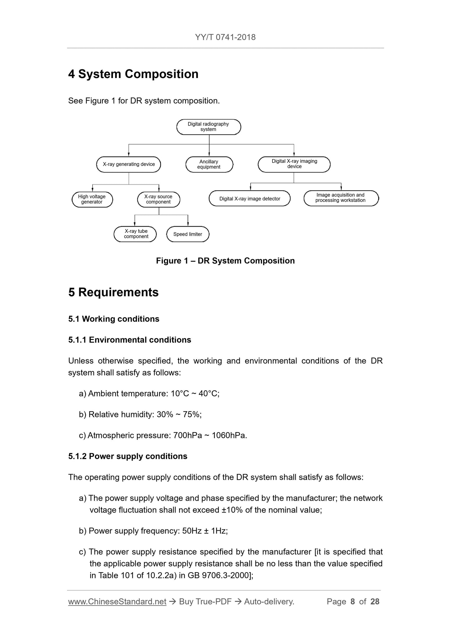
Scope
This Standard specifies the terms and definitions, system composition, requirementsand test methods for digital X-ray radiography system (hereinafter referred to as DR
system).
This Standard is applicable to the DR system for general X-ray photography. It includes
but not limited to DR systems that use line scan or area scan detectors, such as:
--- DR system using flat panel detector (FPD);
--- DR system using area array CCD detector;
--- DR system using line array scanning CCD detector;
--- DR system using CMOS detector, etc.
Corresponding to the DR system using more than one digital X-ray image detector,
this Standard is applicable to each digital X-ray image detector and the X-ray
generating device used in its imaging.
This Standard is not applicable to system using X-ray image intensifier, system using
imaging device of image plate for X-ray photography, mammary X-ray equipment,
dental X-ray equipment, computed tomography equipment, mobile DR system.
Basic Data
| Standard ID | YY/T 0741-2018 (YY/T0741-2018) |
| Description (Translated English) | Particular Specifications for Digital X-Ray Radiography System |
| Sector / Industry | Medical Device and Pharmaceutical Industry Standard (Recommended) |
| Classification of Chinese Standard | C43 |
| Classification of International Standard | 11.040.50 |
| Word Count Estimation | 18,179 |
| Date of Issue | 2018-09-28 |
| Date of Implementation | 2019-10-01 |
| Older Standard (superseded by this standard) | YY/T 0741-2009 |
| Quoted Standard | GB 9706.1; GB 9706.3-2000; GB 9706.11; GB 9706.12-1997; GB 9706.14; GB 9706.15; GB/T 10151; YY/T 0291; YY 0505; DICOM 3.0 |
| Regulation (derived from) | State Drug Administration Announcement No. 72 of 2018 |
| Issuing agency(ies) | State Drug Administration |
| Summary | This standard specifies the terms and definitions, system components, requirements and test methods of digital photographic X-ray machines (hereinafter referred to as DR systems). This standard applies to DR systems for general X-ray photography. Including but not limited to DR systems using line scan or area array scanning detectors, such as: 1. DR system using flat panel detector (FPD); 2. DR system using area array CCD detector; 3. Using line array Scan the DR system of the CCD detector; 4. Use the DR system of the CMOS detector. Corresponding to the DR system using more than one digital X-ray image detector, this standard applies to each digital X-ray image detector and its X-ray generating device used in imaging. This standard does not apply to systems using X-ray image intensifiers. |
Share