Skip to product information
1 of 7

PayPal, credit cards. Download editable-PDF and invoice in 1 second!

TB/T 3111-2017 English PDF (TBT3111-2017)

TB/T 3111-2017 English PDF (TBT3111-2017)

Regular price $170.00 USD
Regular price Sale price $170.00 USD
Sale Sold out
Shipping calculated at checkout.
Delivery: 3 seconds. Download true-PDF + Invoice.
Get QUOTATION in 1-minute: Click TB/T 3111-2017
Historical versions: TB/T 3111-2017
Preview True-PDF (Reload/Scroll if blank)

TB/T 3111-2017: Copper and copper alloy stranded conductors for electric railway
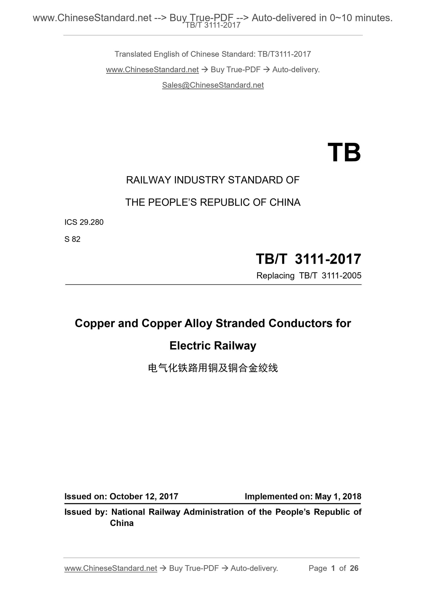
TB/T 3111-2017
RAILWAY INDUSTRY STANDARD OF
THE PEOPLE’S REPUBLIC OF CHINA
ICS 29.280
S 82
Replacing TB/T 3111-2005
Copper and Copper Alloy Stranded Conductors for
Electric Railway
ISSUED ON: OCTOBER 12, 2017
IMPLEMENTED ON: MAY 1, 2018
Issued by: National Railway Administration of the People’s Republic of
China
Table of Contents
Foreword ... 3 
1 Scope ... 5 
2 Normative References ... 5 
3 Terms and Definitions ... 5 
4 Product Classification ... 6 
5 Materials ... 8 
6 Technical Requirements ... 9 
7 Inspection Methods ... 16 
8 Inspection Rules and Result Determination ... 20 
9 Packaging and Marking ... 22 
10 Storage and Transportation ... 23 
Appendix A (informative) Calculated Value of Unit Mass and Nominal Value of
Pulling Force of Stranded Conductor ... 24 
Bibliography ... 26 
Copper and Copper Alloy Stranded Conductors for
Electric Railway
1 Scope
This Standard stipulates the terms and definitions, product classification, materials,
technical requirements, test methods, inspection rules, packaging, marking, storage
and transportation of circular concentric-lay-stranded conductor, multiple stranded
copper and copper alloy stranded conductor for electric railway (hereinafter referred to
as stranded conductor).
This Standard is applicable to various models and specifications of copper and copper
alloy stranded conductors for the overhead contact system in the field of electric railway.
Copper and copper alloy stranded conductors for the overhead contact system in the
field of urban railway system, and industrial and mining enterprises may also take this
Standard as a reference.
2 Normative References
The following documents are indispensable to the application of this document. In
terms of references with a specified date, only versions with a specified date are
applicable to this document. In terms of references without a specified date, the latest
version (including all the modifications) is applicable to this document.
GB/T 467-2010 Copper Cathode
3 Terms and Definitions
The following terms and definitions are applicable to this document.
3.1 Stranded Conductor
Stranded conductor refers to a kind of material, which is used to transmit current and
(or) bear certain tension. Stranded conductor is made by stranding multiple single
conducting wires or strands.
3.2 Concentric-lay-stranded Conductor
Concentric-lay-stranded conductor is a conductor constituted by spirally stranding one
lay or multiple lays of single conducting wire around a center line. It is also known as
concentric-lay-stranded wire. In the adjacent lay, the direction of lay is opposite.
3.3 Multiple Stranded Conductor
Multiple stranded conductor refers to a conductor, which is formed by the stranding of
several wire sets through one or multiple spiral lays. In each wire set, single conducting
wire may be bunched or stranded.
3.4 Direction of Lay
Direction of lay refers to the stranding direction of one lay of single conducting wire or
strand. In other words, it refers to the direction of movement after leaving the observer.
3.5 Length of Lay
Length of lay refers to the axial length of a whole spiral formed by one single conducting
wire or strand in stranded conductor.
3.6 Lay Ratio
Lay ratio refers to the ratio of the length of lay of a single conducting wire or strand in
stranded conductor to the external diameter of the lay.
3.7 Single Conducting Wire
Single conducting wire refers to drawn metal wire which has a stipulated circular cross-
section.
3.8 Concentric Strand
Concentric strand refers to an element in multiple stranded conductor. Each element
is constituted of a set of concentrically stranded single conducting wires.
3.9 Bunched Strand
Bunched strand refers to an element in multiple stranded conductor. Single conducting
wires of each element are spirally stranded together in the same direction and the
same length of lay. However, stratification is not required here.
4 Product Classification
4.1 Classification and Model
Copper and copper alloy stranded conductors shall be classified in accordance with
the category of copper and its alloy elements, and tensile strength rating. Each
category can also be divided into different specifications in accordance with the cross-
sectional area. Product model shall be expressed in the following form.
In accordance with GB/T 4909.2, adopt the test method of paper tape to measure the
length of lay of the stranded conductor, then, calculate the lay ratio of the stranded
conductor.
7.3 Measurement of Diameter of Single Conducting Wire
Since single conducting wire is already deformed after the stranding, a blade-type
micrometer shall be used, or, a slice (thickness: 1 mm) shall be put on a universal
microscope to measure its diameter. In addition, in the same cross-section, measure
two mutually vertical values; take the average value.
7.4 Pulling Force of Stranded Conductor, Pulling Force Test after Vibration
Test and Fatigue Test
7.4.1 In accordance with TB/T 2074, on both ends of a stranded conductor with the
gauge length of 5 m, respectively crimp it with 200 mm seamless steel pipe. Then,
clamp the sample on a horizontal tension machine, at the rate of not more than 20
mm/min, uniformly load it. When a single conducting wire ruptures, or, completely
breaks off, stop the loading; record the maximum force value. If the sample ruptures
inside the crimped pipe, or, at a distance of less than 20 mm from the pipe mouth, and
the test force value is less than the value stipulated in the Standard, then, the test shall
be invalid. The test shall be re-conducted.
7.4.2 Use terminal anchor clamp for the pulling force test of stranded conductor.
7.5 DC Resistance, Electrical Resistivity and Electrical Conductivity Test
In accordance with GB/T 3048.2, adopt double-arm bridge and four-terminal method
for measurement.
Before the measurement, place the sample in a thermostatic chamber at 20 °C ± 0.5 °C
for 24 h. Install the sample on the fixture. Measure DC resistance of the stranded
conductor: impose 8 A of current. Measure electrical resistivity or electrical conductivity
of single conducting wire: impose 4 A of current. During the measurement, in order to
eliminate the influence of thermoelectric potential, adopt the method of reversing the
positive and negative electrode of current, and taking the average value. If there is
stain or rust on the surface of the sample, use alcohol cotton or fine sandpaper to get
rid of it, then, conduct the measurement. If the ambient temperature does not satisfy
20 °C ± 0.5 °C (however, the ambient temperature still needs to be controlled within
the range of 20 °C ± 5 °C), in accordance with the temperature coefficient of resistance,
convert it to the resistance, electrical resistivity and electrical conductivity at 20 °C.
Temperature coefficient of resistance is shown in Table 3.
7.6 Tensile Strength Test and Elongation Rate Measurement after
Stranding of Single Conducting Wire
The gauge length of the sample shall be 250 mm. Firstly, measure the diameter of the
the stranded conductor; impose the test current. In every 30 min, measure the
temperature once. When the difference between the temperature measured in 3
consecutive times and the maximum allowable operating temperature T is not more
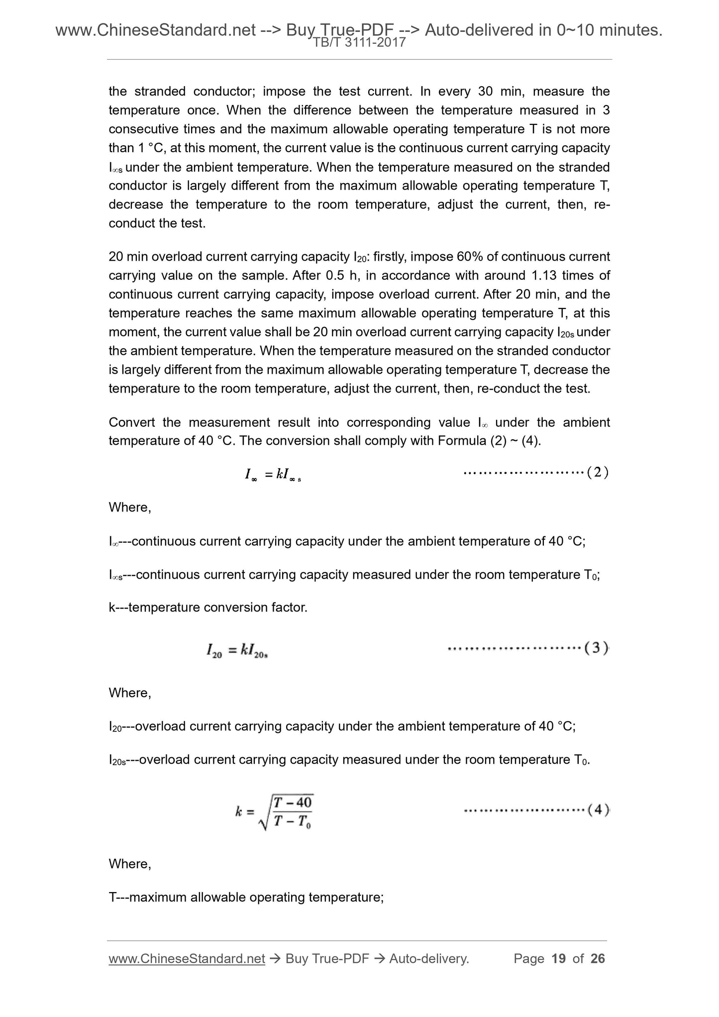
than 1 °C, at this moment, the current value is the continuous current carrying capacity
Is under t...
View full details