1
/
of
7
www.ChineseStandard.us -- Field Test Asia Pte. Ltd.
TB/T 2809-2017 English PDF (TB/T2809-2017)
TB/T 2809-2017 English PDF (TB/T2809-2017)
Regular price
$145.00
Regular price
Sale price
$145.00
Unit price
/
per
Shipping calculated at checkout.
Couldn't load pickup availability
TB/T 2809-2017: Copper and copper alloy contact wires for electric railway
Delivery: 9 seconds. Download (and Email) true-PDF + Invoice.Get Quotation: Click TB/T 2809-2017 (Self-service in 1-minute)
Newer / historical versions: TB/T 2809-2017
Preview True-PDF
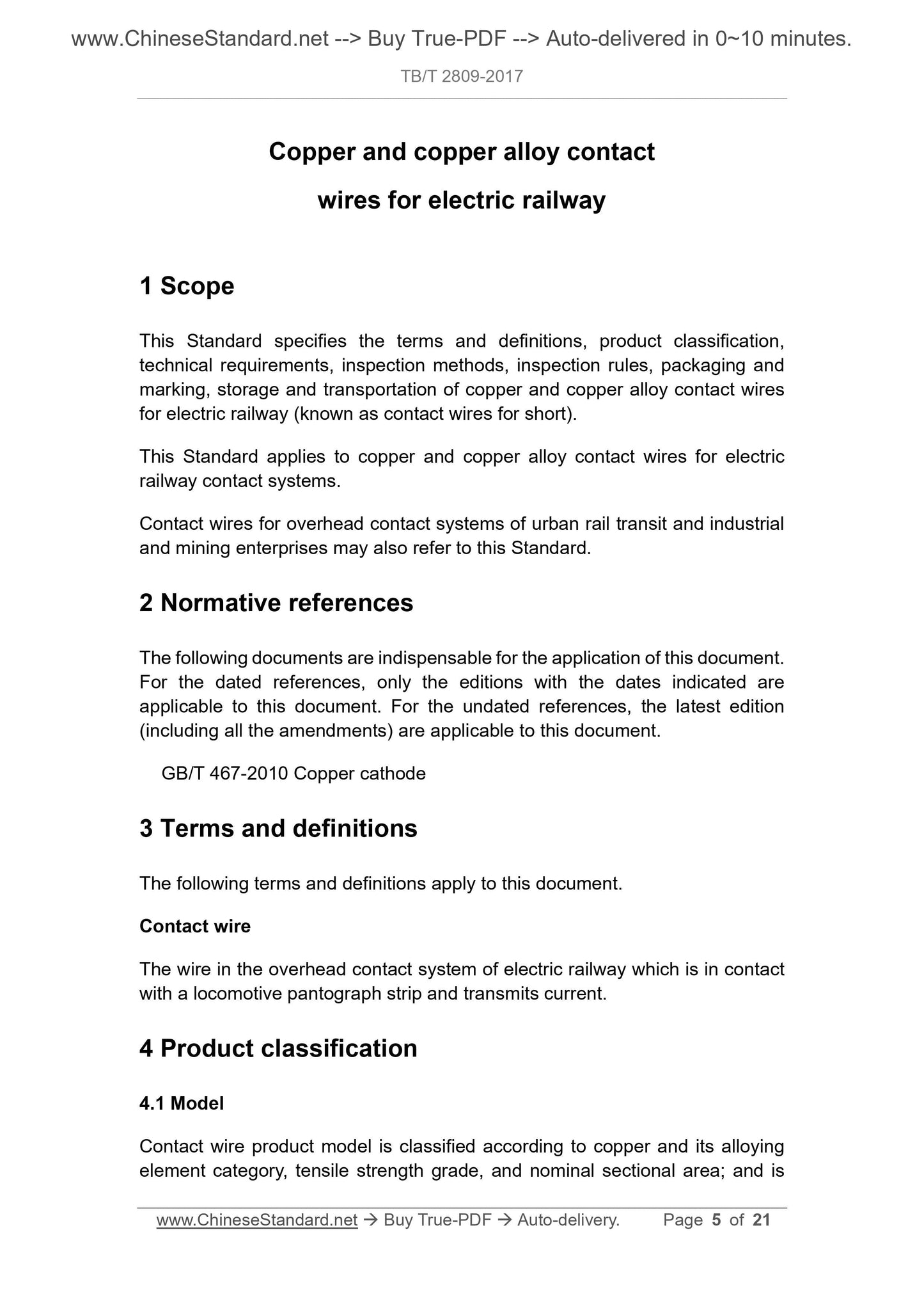
Scope
This Standard specifies the terms and definitions, product classification,technical requirements, inspection methods, inspection rules, packaging and
marking, storage and transportation of copper and copper alloy contact wires
for electric railway (known as contact wires for short).
This Standard applies to copper and copper alloy contact wires for electric
railway contact systems.
Contact wires for overhead contact systems of urban rail transit and industrial
and mining enterprises may also refer to this Standard.
Basic Data
| Standard ID | TB/T 2809-2017 (TB/T2809-2017) |
| Description (Translated English) | Copper and copper alloy contact wires for electric railway |
| Sector / Industry | Railway and Train Industry Standard (Recommended) |
| Classification of Chinese Standard | S82 |
| Classification of International Standard | 29.280 |
| Word Count Estimation | 13,111 |
| Date of Issue | 2017-10-12 |
| Date of Implementation | 2018-05-01 |
| Older Standard (superseded by this standard) | TB/T 2809-2005 |
| Quoted Standard | GB/T 467-2010 |
| Regulation (derived from) | National-Railway-Technology-Regulation (2017) 74 |
| Issuing agency(ies) | National Railway Administration |
Share