www.ChineseStandard.us -- Field Test Asia Pte. Ltd.
Regular price
$135.00
Regular price
Sale price
$135.00
Unit price
/
per
Sale
Sold out
Couldn't load pickup availability
Refresh
TB/T 1632.4-2014: Welding of rails - Part 4: Gas pressure welding Delivery: 9 seconds. Download (and Email) true-PDF + Invoice.
Get Quotation: Click
TB/T 1632.4-2014 (Self-service in 1-minute)
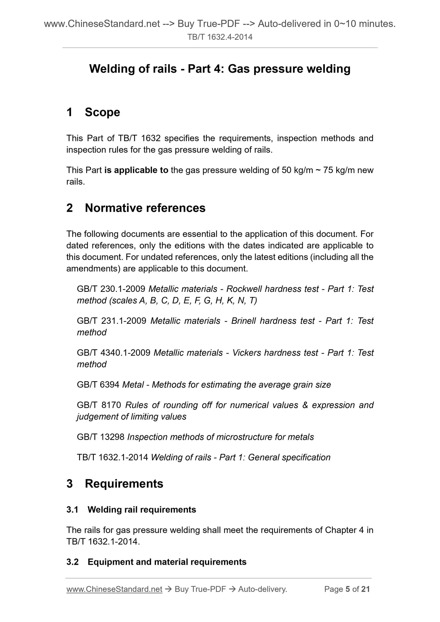
Newer / historical versions: TB/T 1632.4-2014 Preview True-PDF Scope This Part of TB/T 1632 specifies the requirements, inspection methods and
inspection rules for the gas pressure welding of rails.
This Part is applicable to the gas pressure welding of 50 kg/m ~ 75 kg/m new
rails.
Basic Data Standard ID TB/T 1632.4-2014 (TB/T1632.4-2014)
Description (Translated English) Welding of rails - Part 4: Gas pressure welding
Sector / Industry Railway and Train Industry Standard (Recommended)
Classification of Chinese Standard S17
Classification of International Standard 45.120
Word Count Estimation 16,124
Date of Issue 10/30/2014
Date of Implementation 5/1/2015
Older Standard (superseded by this standard) TB/T 1632.4-2005
Regulation (derived from) State-Railway-Science-Regulations [2014] 55
Issuing agency(ies) National Railway Administration
View full details