Skip to product information
1 of 9

PayPal, credit cards. Download editable-PDF & invoice in 1 second!

QC/T 660-2019 English PDF (QCT660-2019)

QC/T 660-2019 English PDF (QCT660-2019)

Regular price $305.00 USD
Regular price Sale price $305.00 USD
Sale Sold out
Shipping calculated at checkout.
Quotation: In 1-minute, 24-hr self-service. Click here QC/T 660-2019 to get it for Purchase Approval, Bank TT...

QC/T 660-2019: The test method for automobile air-conditioning compressors

This Standard specifies the test method for automobile air-conditioning compressors. This Standard is applicable to various types of pulley-driven automobile airconditioning compressors that use HFC-134a/HFO-1234yf refrigerants. Other environmentally-friendly refrigerant compressors can be implemented by reference.
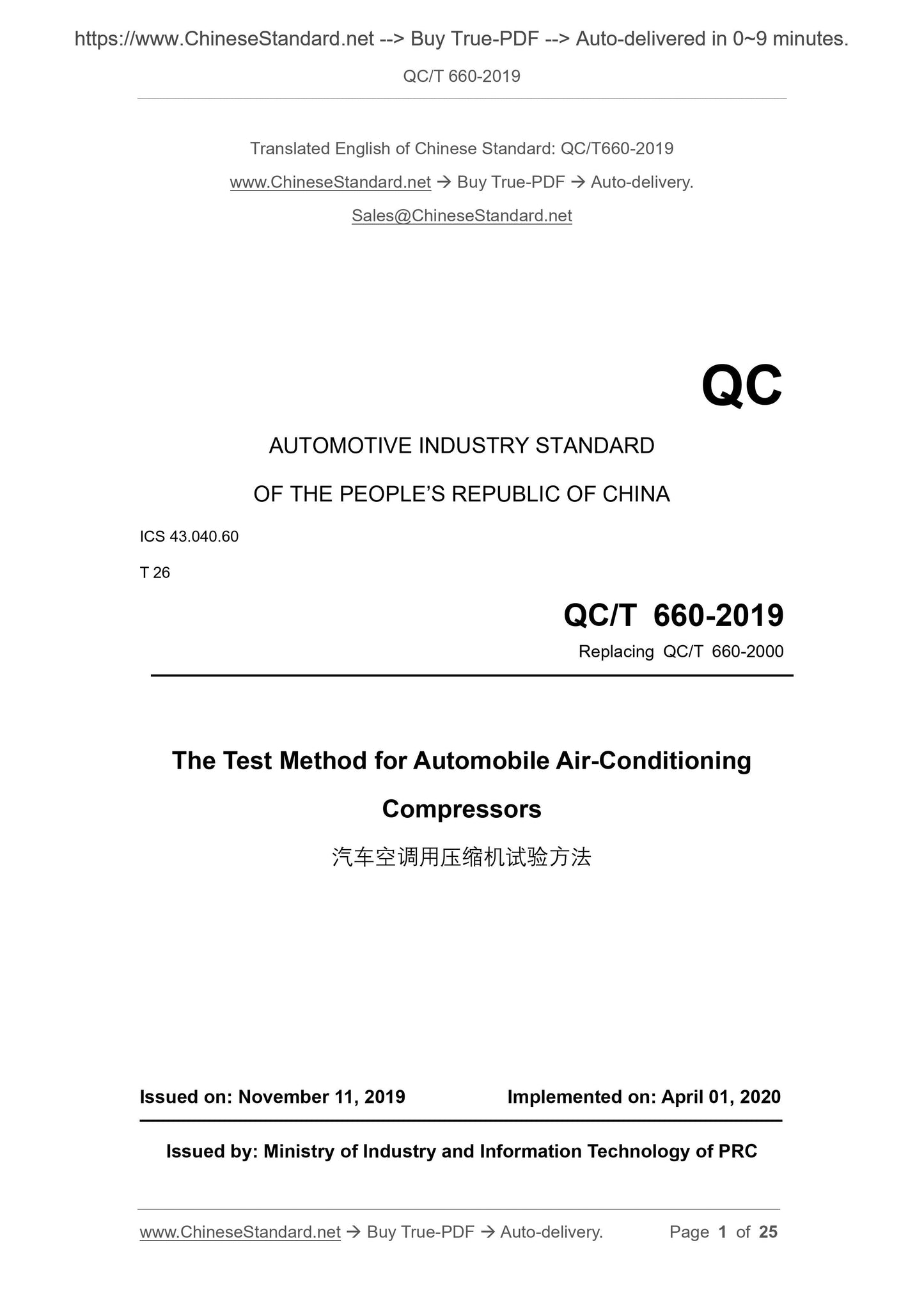
QC/T 660-2019
QC
AUTOMOTIVE INDUSTRY STANDARD
OF THE PEOPLE’S REPUBLIC OF CHINA
ICS 43.040.60
T 26
Replacing QC/T 660-2000
The Test Method for Automobile Air-Conditioning
Compressors
ISSUED ON: NOVEMBER 11, 2019
IMPLEMENTED ON: APRIL 01, 2020
Issued by: Ministry of Industry and Information Technology of PRC
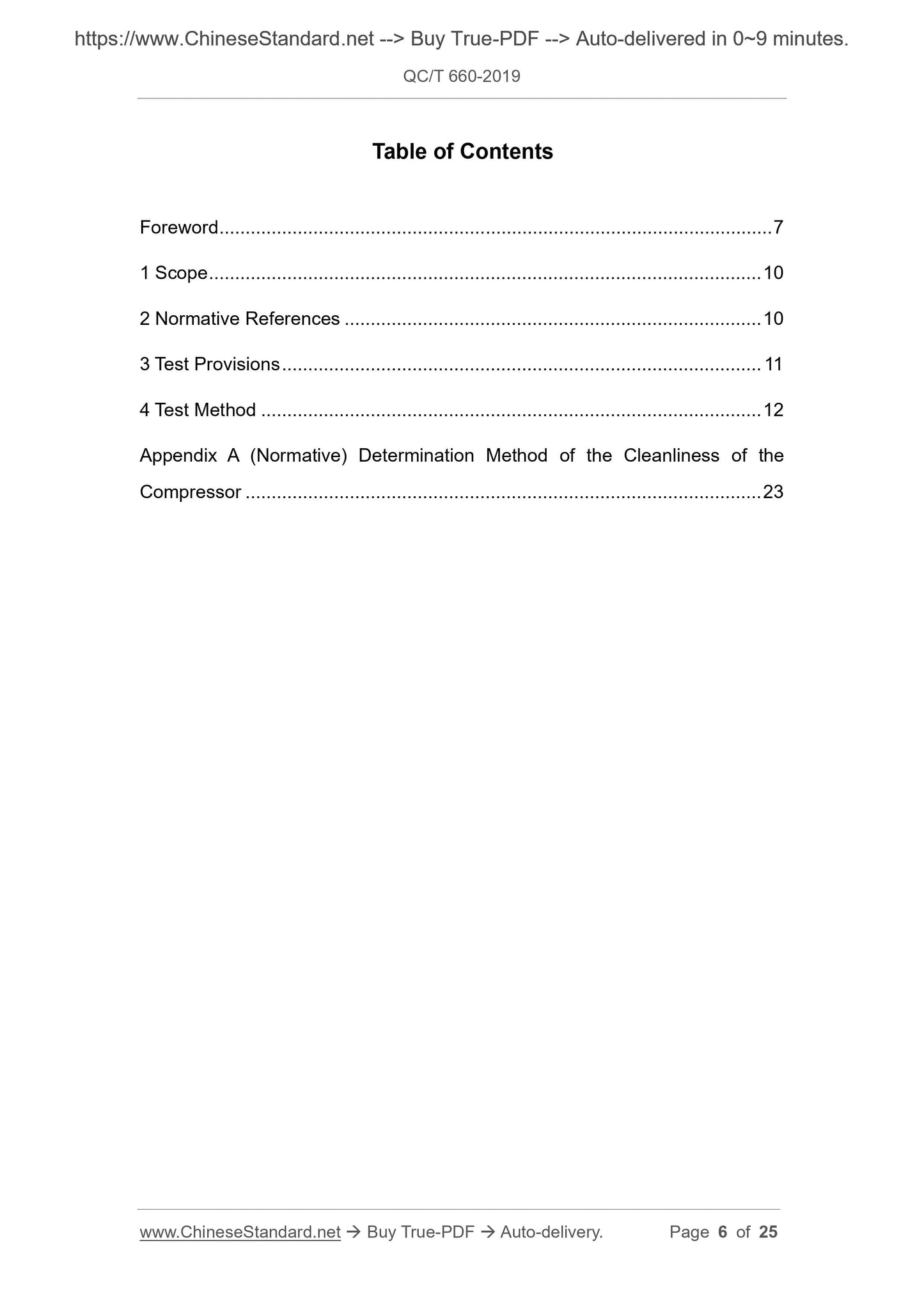
Table of Contents
Foreword ... 7
1 Scope ... 10
2 Normative References ... 10
3 Test Provisions ... 11
4 Test Method ... 12
Appendix A (Normative) Determination Method of the Cleanliness of the
Compressor ... 23
The Test Method for Automobile Air-Conditioning
Compressors
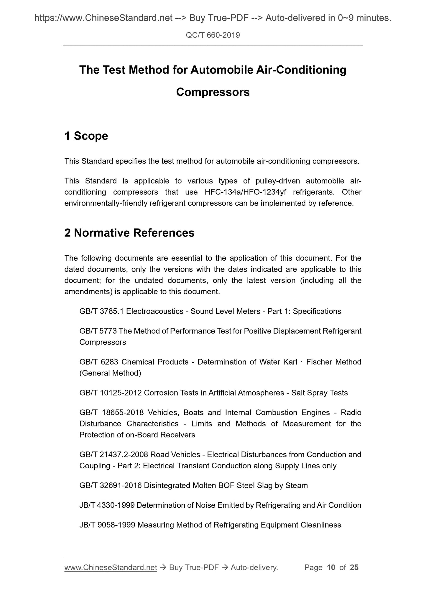
1 Scope
This Standard specifies the test method for automobile air-conditioning compressors. This Standard is applicable to various types of pulley-driven automobile air- conditioning compressors that use HFC-134a/HFO-1234yf refrigerants. Other environmentally-friendly refrigerant compressors can be implemented by reference. 2 Normative References
The following documents are essential to the application of this document. For the dated documents, only the versions with the dates indicated are applicable to this document; for the undated documents, only the latest version (including all the amendments) is applicable to this document.
GB/T 3785.1 Electroacoustics - Sound Level Meters - Part 1: Specifications GB/T 5773 The Method of Performance Test for Positive Displacement Refrigerant Compressors
GB/T 6283 Chemical Products - Determination of Water Karl · Fischer Method (General Method)
GB/T 10125-2012 Corrosion Tests in Artificial Atmospheres - Salt Spray Tests GB/T 18655-2018 Vehicles, Boats and Internal Combustion Engines - Radio Disturbance Characteristics - Limits and Methods of Measurement for the Protection of on-Board Receivers
GB/T 21437.2-2008 Road Vehicles - Electrical Disturbances from Conduction and Coupling - Part 2: Electrical Transient Conduction along Supply Lines only GB/T 32691-2016 Disintegrated Molten BOF Steel Slag by Steam
JB/T 4330-1999 Determination of Noise Emitted by Refrigerating and Air Condition JB/T 9058-1999 Measuring Method of Refrigerating Equipment Cleanliness
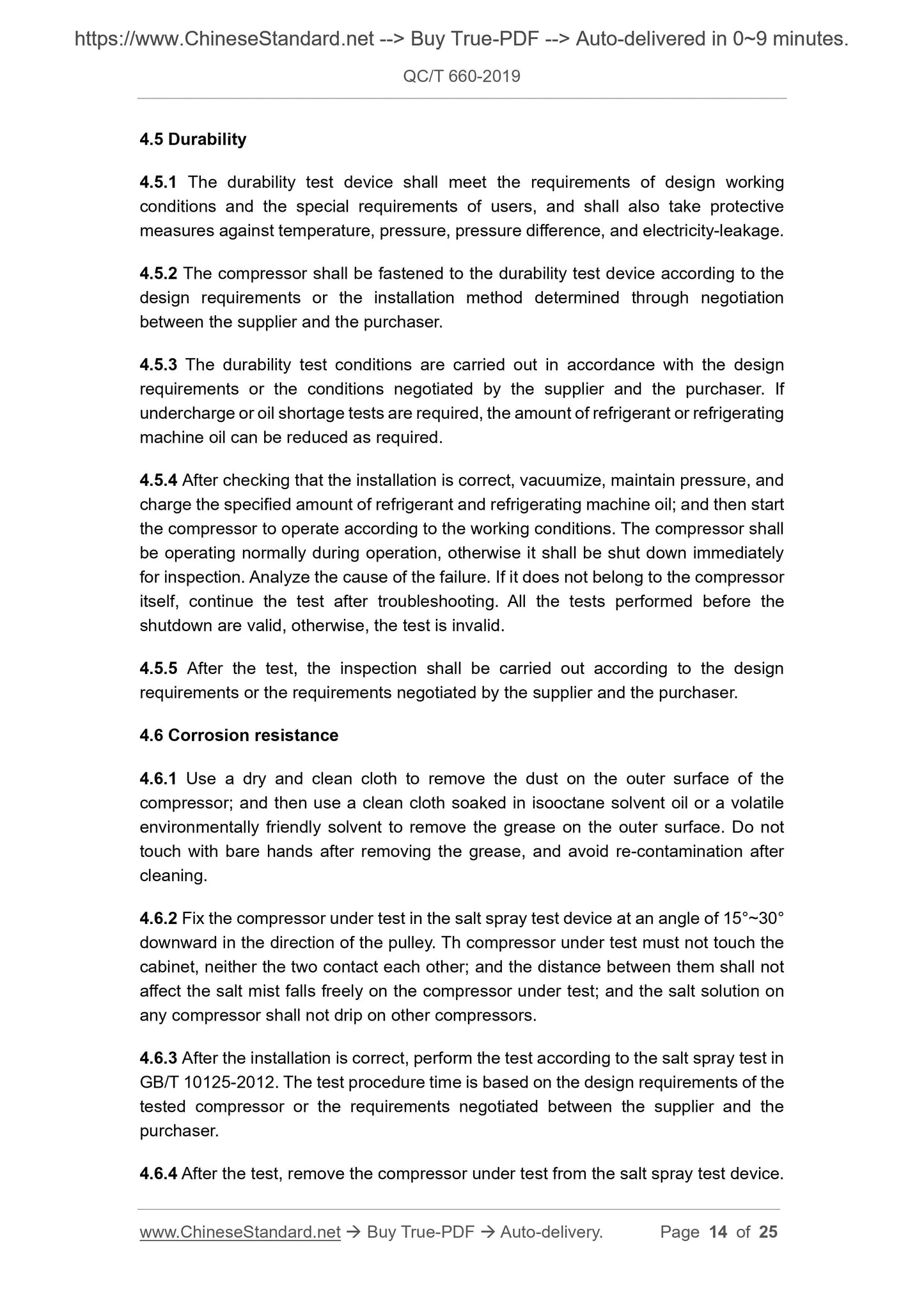
4.5 Durability
4.5.1 The durability test device shall meet the requirements of design working conditions and the special requirements of users, and shall also take protective measures against temperature, pressure, pressure difference, and electricity-leakage. 4.5.2 The compressor shall be fastened to the durability test device according to the design requirements or the installation method determined through negotiation between the supplier and the purchaser.
4.5.3 The durability test conditions are carried out in accordance with the design requirements or the conditions negotiated by the supplier and the purchaser. If undercharge or oil shortage tests are required, the amount of refrigerant or refrigerating machine oil can be reduced as required.
4.5.4 After checking that the installation is correct, vacuumize, maintain pressure, and charge the specified amount of refrigerant and refrigerating machine oil; and then start the compressor to operate according to the working conditions. The compressor shall be operating normally during operation, otherwise it shall be shut down immediately for inspection. Analyze the cause of the failure. If it does not belong to the compressor itself, continue the test after troubleshooting. All the tests performed before the shutdown are valid, otherwise, the test is invalid.
4.5.5 After the test, the inspection shall be carried out according to the design requirements or the requirements negotiated by the supplier and the purchaser. 4.6 Corrosion resistance
4.6.1 Use a dry and clean cloth to remove the dust on the outer surface of the compressor; and then use a clean cloth soaked in isooctane solvent oil or a volatile environmentally friendly solvent to remove the grease on the outer surface. Do not touch with bare hands after removing the grease, and avoid re-contamination after cleaning.
4.6.2 Fix the compressor under test in the salt spray test device at an angle of 15°~30° downward in the direction of the pulley. Th compressor under test must not touch the cabinet, neither the two contact each other; and the distance between them shall not affect the salt mist falls freely on the compressor under test; and the salt solution on any compressor shall not drip on other compressors.
4.6.3 After the installation is correct, perform the test according to the salt spray test in GB/T 10125-2012. The test procedure time is based on the design requirements of the tested compressor or the requirements negotiated between the supplier and the purchaser.
4.6.4 After the test, remove the compressor under test from the salt spray test device. 4.6.5 Remove the clutch from the compressor under test.
4.6.6 Wash the clutch and compressor by water to remove all salt deposits on the surface; and immediately dry the clutch and compressor by strong hot air. 4.6.7 After drying, immediately inspect and record the compressor under test in accordance with the provisions of Clause 11 of GB/T 10125-2012.
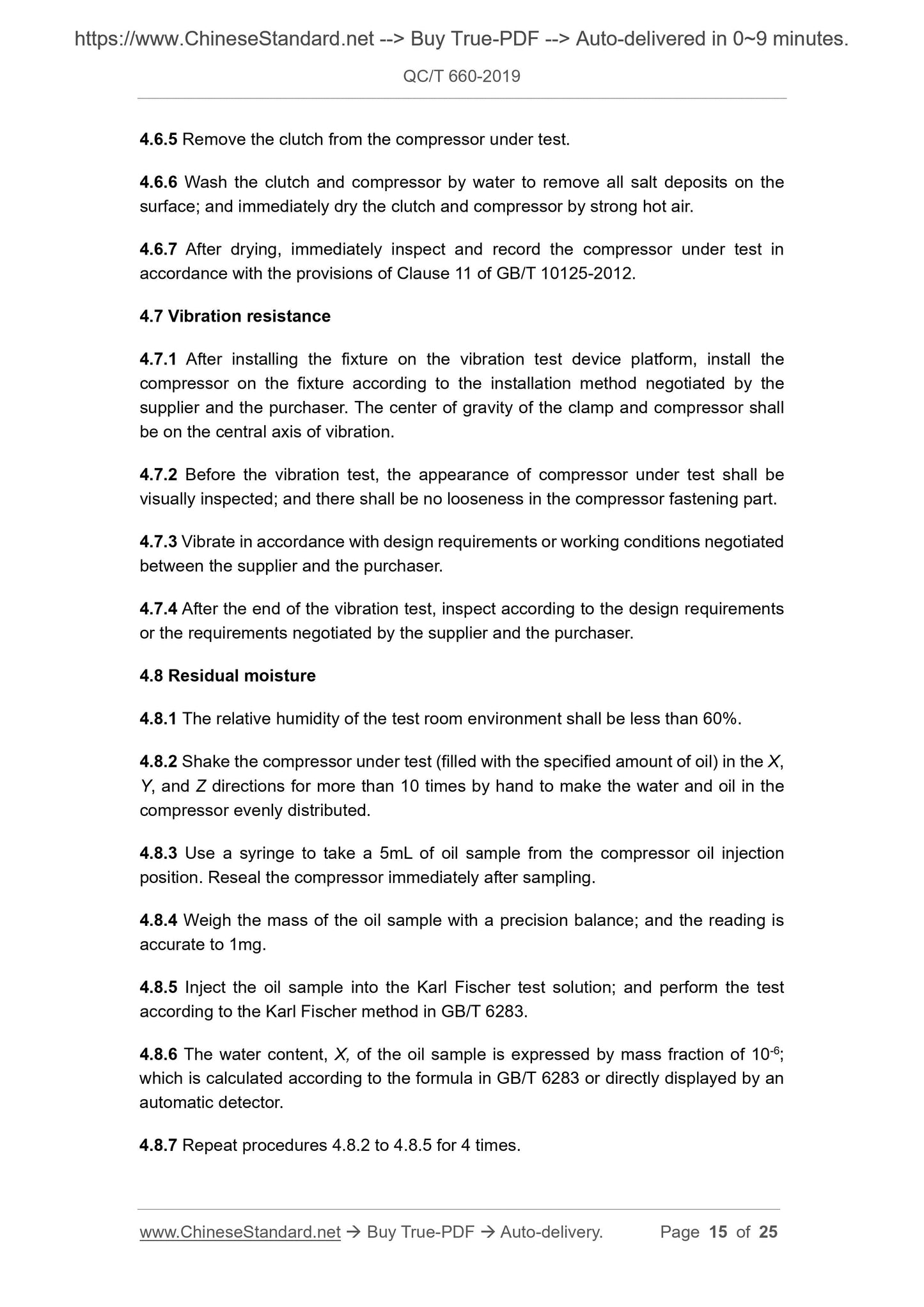
4.7 Vibration resistance
4.7.1 After installing the fixture on the vibration test device platform, install the compressor on the fixture according to the installation method negotiated by the supplier and the purchaser. The center of gravity of the clamp and compressor shall be on the central axis of vibration.
4.7.2 Before the vibration test, the appearance of compressor under test shall be visually inspected; and there shall be no looseness in the compressor fastening part. 4.7.3 Vibrate in accordance with design requirements or working conditions negotiated between the supplier and the purchaser.
4.7.4 After the end of the vibration test, inspect according to the design requirements or the requirements negotiated by the supplier and the purchaser.
4.8 Residual moisture
4.8.1 The relative humidity of the test room environment shall be less than 60%. 4.8.2 Shake the compressor under test (filled with the specified amount of oil) in the X, Y, and Z directions for more than 10 times by hand to make the water and oil in the compressor evenly distributed.
4.8.3 Use a syringe to take a 5mL of oil sample from the compressor oil injection position. Reseal the compressor immediately after sampling.
4.8.4 Weigh the mass of the oil sample with a precision balance; and the reading is accurate to 1mg.
4.8.5 Inject the oil sample into the Karl Fischer test solution; and perform the test according to the Karl Fischer method in GB/T 6283.
4.8.6 The water content, X, of the oil sample is expressed by mass fraction of 10-6; which is calculated according to the formula in GB/T 6283 or directly displayed by an automatic detector.
4.8.7 Repeat procedures 4.8.2 to 4.8.5 for 4 times.
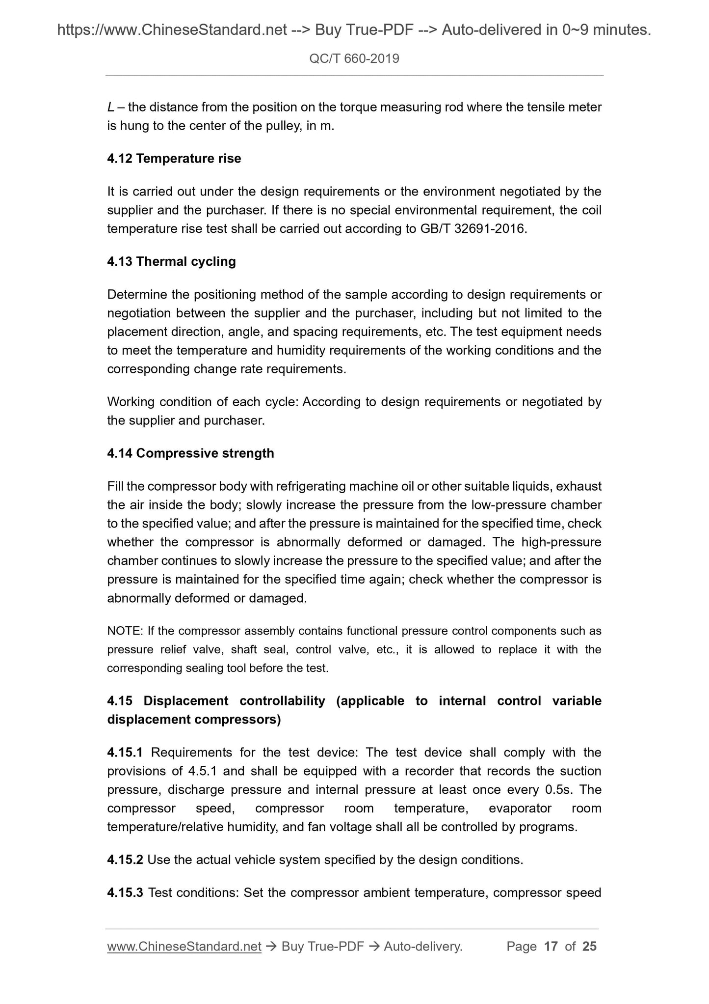
L – the distance from the position on the torque measuring rod where the tensile meter is hung to the center of the pulley, in m.
4.12 Temperature rise
It is carried out under the design requirements or the environment negotiated by the supplier and the purchaser. If there is no special environmental requirement, the coil temperature rise test shall be carried out according to GB/T 32691-2016. 4.13 Thermal cycling
Determine the positioning method of the sample according to design requirements or negotiation between the supplier and the purchaser, including but not limited to the placement direction, angle, and spacing requirements, etc. The test equipment needs to meet the temperature and humidity requirements of the working conditions and the corresponding change rate requirements.
Working condition of each cycle: According to design requirements or negotiated by the supplier and purchaser.
4.14 Compressive strength
Fill the compressor body with refrigerating machine oil or other suitable liquids, exhaust the air inside the body; slowly increase the pressure from the low-pressure chamber to the specified value; and after the pressure is maintained for the specified time, check whether the compressor is abnormally deformed or damaged. The high-pressure chamber continues to slowly increase the pressure to the specified value; and after the pressure is maintained for the specified time again; check whether the compressor is abnormally deformed or damaged.
NOTE: If the compressor assembly contains functional pressure control components such as pressure relief valve, shaft seal, control valve, etc., it is allowed to replace it with the corresponding sealing tool before the test.
4.15 Displacement controllability (applicable to internal control variable displacement compressors)
4.15.1 Requirements for the test device: The test device shall comply with the provisions of 4.5.1 and shall be equipped with a recorder that records the suction pressure, discharge pressure and internal pressure at least once every 0.5s. The compressor speed, compressor room temperature, evaporator room
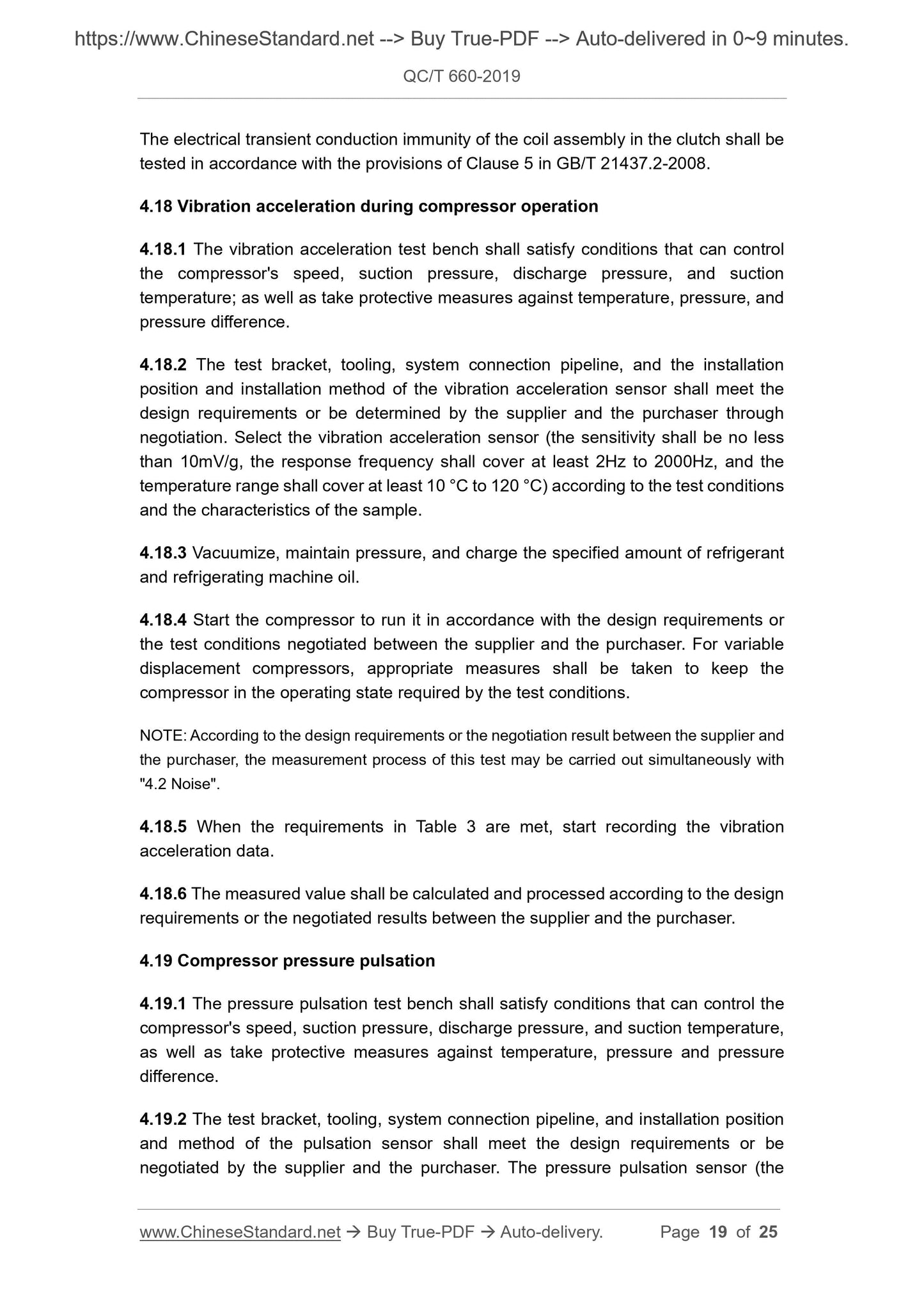
temperature/relative humidity, and fan voltage shall all be controlled by programs. 4.15.2 Use the actual vehicle system specified by the design conditions. 4.15.3 Test conditions: Set the compressor ambient temperature, compressor speed The electrical transient conduction immunity of the coil assembly in the clutch shall be tested in accordance with the provisions of Clause 5 in GB/T 21437.2-2008. 4.18 Vibration acceleration during compressor operation
4.18.1 The vibration acceleration test bench shall satisfy conditions that can control the compressor's speed, suction pressure, discharge pressure, and suction temperature; as well as take protective measures against temperature, pressure, and pressure difference.
4.18.2 The test bracket, tooling, system connection pipeline, and the installation position and installation method of the vibration acceleration sensor shall meet the design requirements or be determined by the supplier and the purchaser through negotiation. Select the vibration acceleration sensor (the sensitivity shall be no less than 10mV/g, the response frequency shall cover at least 2Hz to 2000Hz, and the temperature range shall cover at least 10 °C to 120 °C) according to the test conditions and the characteristics of the sample.
4.18.3 Vacuumize, maintain pressure, and charge the specified amount of refrigerant and refrigerating machine oil.
4.18.4 Start the compressor to run it in accordance with the design requirements or the test conditions negotiated between the supplier and the purchaser. For variable displacement compressors, appropriate measures shall be taken to keep the compressor in the operating state required by the test conditions.
NOTE: According to the design requirements or the negotiation result between the supplier and the purchaser, the measurement process of this test may be carried out simultaneously with "4.2 Noise".
4.18.5 When the requirements in Table 3 are met, start recording the vibration acceleration data.
4.18.6 The measured value shall be calculated and processed according to the design requirements or the negotiated results between the supplier and the purchaser. 4.19 Compressor pressure pulsation
4.19.1 The pressure pulsation test bench shall satisfy conditions that can control the compressor's speed, suction pressure, discharge pressure, and suction temperature, as well as take protective measures against temperature, pressure and pressure difference.
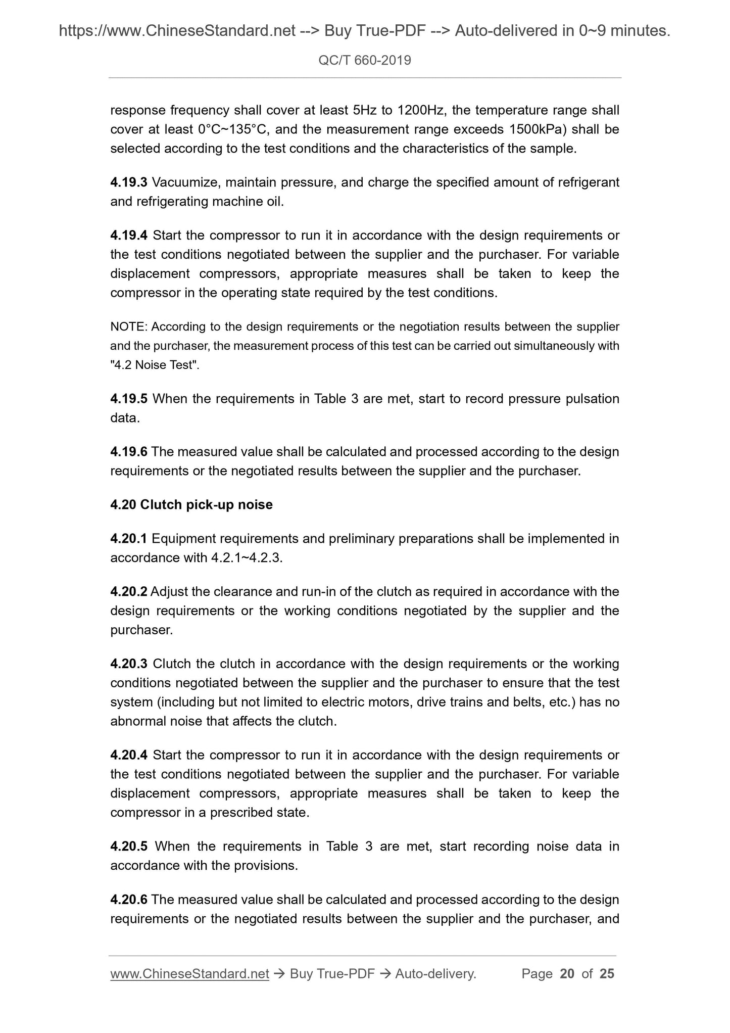
4.19.2 The test bracket, tooling, system connection pipeline, and installation position and method of the pulsation sensor shall meet the design requirements or be negotiated by the supplier and the purchaser. The pressure pulsation sensor (the response frequency shall cover at least 5Hz to 1200Hz, the temperature range shall cover at least 0°C~135°C, and the measurement range exceeds 1500kPa) shall be selected according to the test conditions and the characteristics of the sample. 4.19.3 Vacuumize, maintain pressure, and charge the specified amount of refrigerant and refrigerating machine oil.
4.19.4 Start the compressor to run it in accordance with the design requirements or the test conditions negotiated between the supplier and the purchaser. For variable displacement compressors, appropriate measures shall be taken to keep the compressor in the operating state required by the test conditions.
NOTE: According to the design requirements or the negotiation results between the supplier and the purchaser, the measurement process of this test can be carried out simultaneously with "4.2 Noise Test".
4.19.5 When the requirements in Table 3 are met, start to record pressure pulsation data.
4.19.6 The measured value shall be calculated and processed according to the design requirements or the negotiated results between the supplier and the purchaser. 4.20 Clutch pick-up noise
4.20.1 Equipment requirements and preliminary preparations shall be implemented in accordance with 4.2.1~4.2.3.
4.20.2 Adjust the clearance and run-in of the clutch as required in accordance with the design requirements or the working conditions negotiated by the supplier and the purchaser.
4.20.3 Clutch the clutch in accordance with the design requirements or the working conditions negotiated between the supplier and the purchaser to ensure that the test system (including but not limited to electric motors, drive trains and belts, etc.) has no abnormal noise that affects the clutch.
4.20.4 Start the compressor to run it in accordance with the design requirements or the test conditions negotiated between the supplier and the purchaser. For variable displacement compressors, appropriate measures shall be taken to keep the compressor in a prescribed state.
4.20.5 When the requirements in Table 3 are met, start recording noise data in accordance with the provisions.
4.20.6 The measured value shall be calculated and processed according to the design requirements or the negotiated results between the supplier and the purchaser, and Appendix A
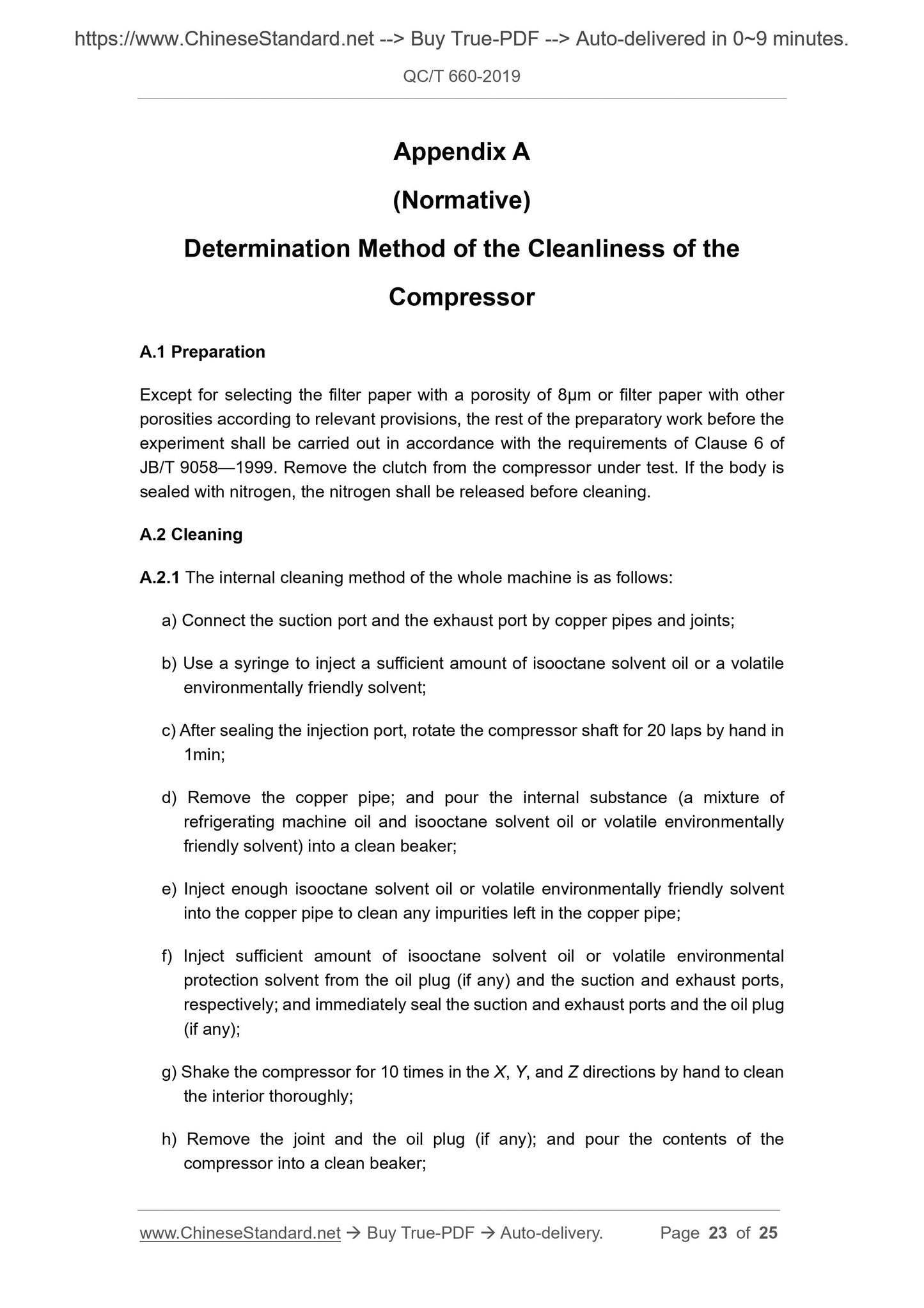
(Normative)
Determination Method of the Cleanliness of the
Compressor
A.1 Preparation
Except for selecting the filter paper with a porosity of 8µm or filter paper with other porosities according to relevant provisions, the rest of the preparatory work before the experiment shall be carried out in accordance with the requirements of Clause 6 of JB/T 9058—1999. Remove the clutch from the compressor under test. If the body is sealed with nitrogen, the nitrogen shall be released before cleaning.
A.2 Cleaning
A.2.1 The internal cleaning method of the whole machine is as follows:
a) Connect the suction port and the exhaust port by copper pipes and joints; b) Use a syringe to inject a sufficient amount of isooctane solvent oil or a volatile environmentally friendly solvent;
c) After sealing the injection port, rotate the compressor shaft for 20 laps by hand in 1min;
d) Remove the copper pipe; and pour the internal substance (a mixture of refrigerating machine oil and isooctane solvent oil or volatile environmentally friendly solvent) into a clean beaker;
e) Inject enough isooctane solvent oil or volatile environmentally friendly solvent into the copper pipe to clean any impurities left in the copper pipe;
f) Inject sufficient amount of isooctane solvent oil or volatile environmental protection solvent from the oil plug (if any) and the suction and exhaust ports, respectively; and immediately seal the suction and exhaust ports and the oil plug (if any);
g) Shake the compressor for 10 times in the X, Y, and Z directions by hand to clean the interior thoroughly;
h) Remove the joint and the oil plug (if any); and pour the contents of the compressor into a clean beaker;

View full details