This standard specifies the terms and definitions, performance requirements, test methods for the bench test of hydraulic brake caliper assemblies for automobile service brakes. This standard applies to the hydraulic brake caliper assembly, for the service brakes of category M and category N vehicle, whose maximum design total mass as specified in GB/T 15089 is less than 3500 kg. Other categories of hydraulic brake calipers may make reference to this standard.
Basic Data
Standard ID
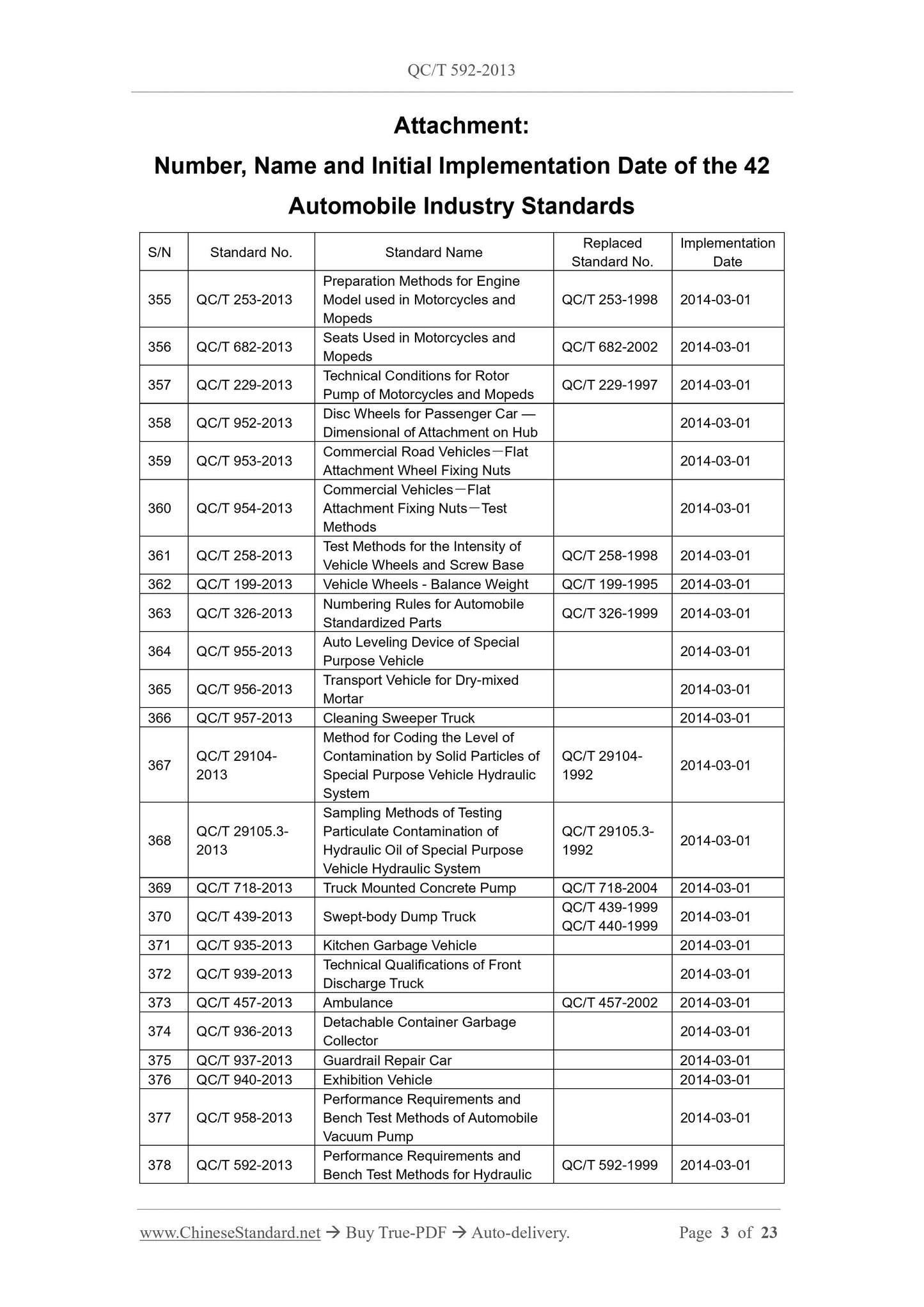
QC/T 592-2013 (QC/T592-2013)
Description (Translated English)
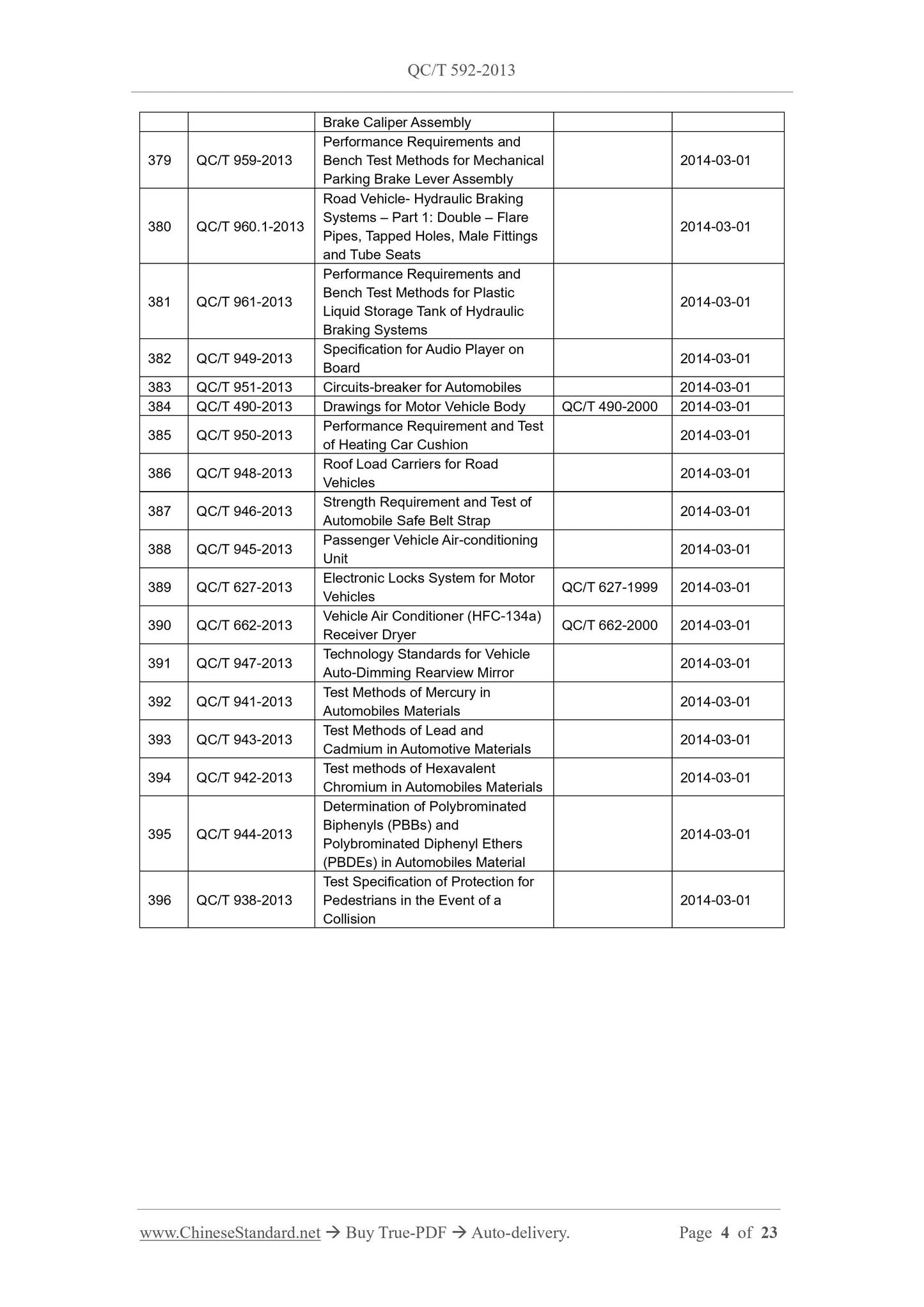
Performance requirements and Bench test methods for Hydraulic brake caliper assembly
Sector / Industry
Automobile and Vehicle Industry Standard (Recommended)
Classification of Chinese Standard
T24
Classification of International Standard
43.040.40
Word Count Estimation
18,140
Older Standard (superseded by this standard)
QC/T 592-1999
Quoted Standard
GB/T 10125-1997; GB/T 15089; QC/T 316
Regulation (derived from)
Ministry of Industry and Information Technology Notice No. 52 of 2013; industry standard for filing Notice 2013 No. 12 (No. 168 overall)
Issuing agency(ies)
Ministry of Industry and Information Technology
Summary
This standard specifies the automotive service brakes with hydraulic brake caliper assembly bench of terms and definitions, performance requirements and test methods. This standard applies to GB/T 15089 stipulated maximum design total mass of less than 35