1.1 This standard specifies the performance requirements and bench test methods for automobile shock absorbers. 1.2 This standard is applicable to the shock absorbers, which are used for the suspension of categories M, N, O automobiles. The shock absorbers for cab suspension and other shock absorber components can be implemented with reference to it.
Basic Data
Standard ID
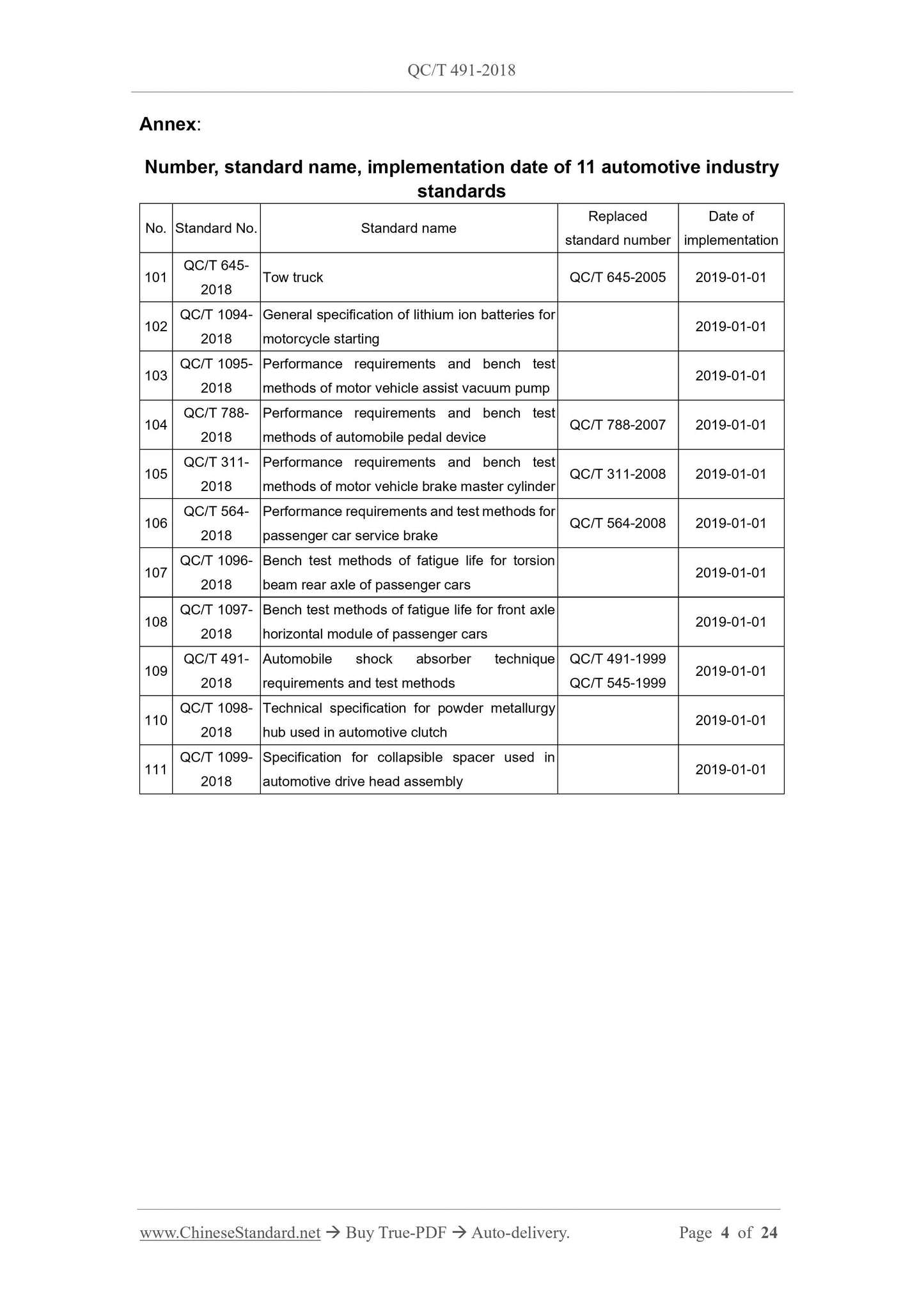
QC/T 491-2018 (QC/T491-2018)
Description (Translated English)
Automobile shock absorber technique requirements and test methods
Sector / Industry
Automobile and Vehicle Industry Standard (Recommended)
Classification of Chinese Standard
T20
Word Count Estimation
17,195
Date of Issue
2018-07-04
Date of Implementation
2019-01-01
Older Standard (superseded by this standard)
QC/T 491-1999; QC/T 545-1999
Regulation (derived from)
Ministry of Industry and Information Technology Announcement No.36 of 2018
Issuing agency(ies)
Ministry of Industry and Information Technology
Summary
This standard specifies the performance requirements of the vehicle damper and the bench test method. This standard is applicable to shock absorbers for M, N, and O type automotive suspensions. Shock absorbers for cab suspension and other shock absorber components can be referred to.