QC/T 1206.2-2024 English PDF (QCT1206.2-2024)
Regular price
$155.00 USD
Regular price
Sale price
$155.00 USD
Unit price
/
per
Delivery: 3 seconds. Download true-PDF + Invoice.
Get QUOTATION in 1-minute: Click QC/T 1206.2-2024
Historical versions: QC/T 1206.2-2024
Preview True-PDF (Reload/Scroll if blank)
QC/T 1206.2-2024: Thermal management system for electric vehicle traction battery - Part 2: Liquid cooling system
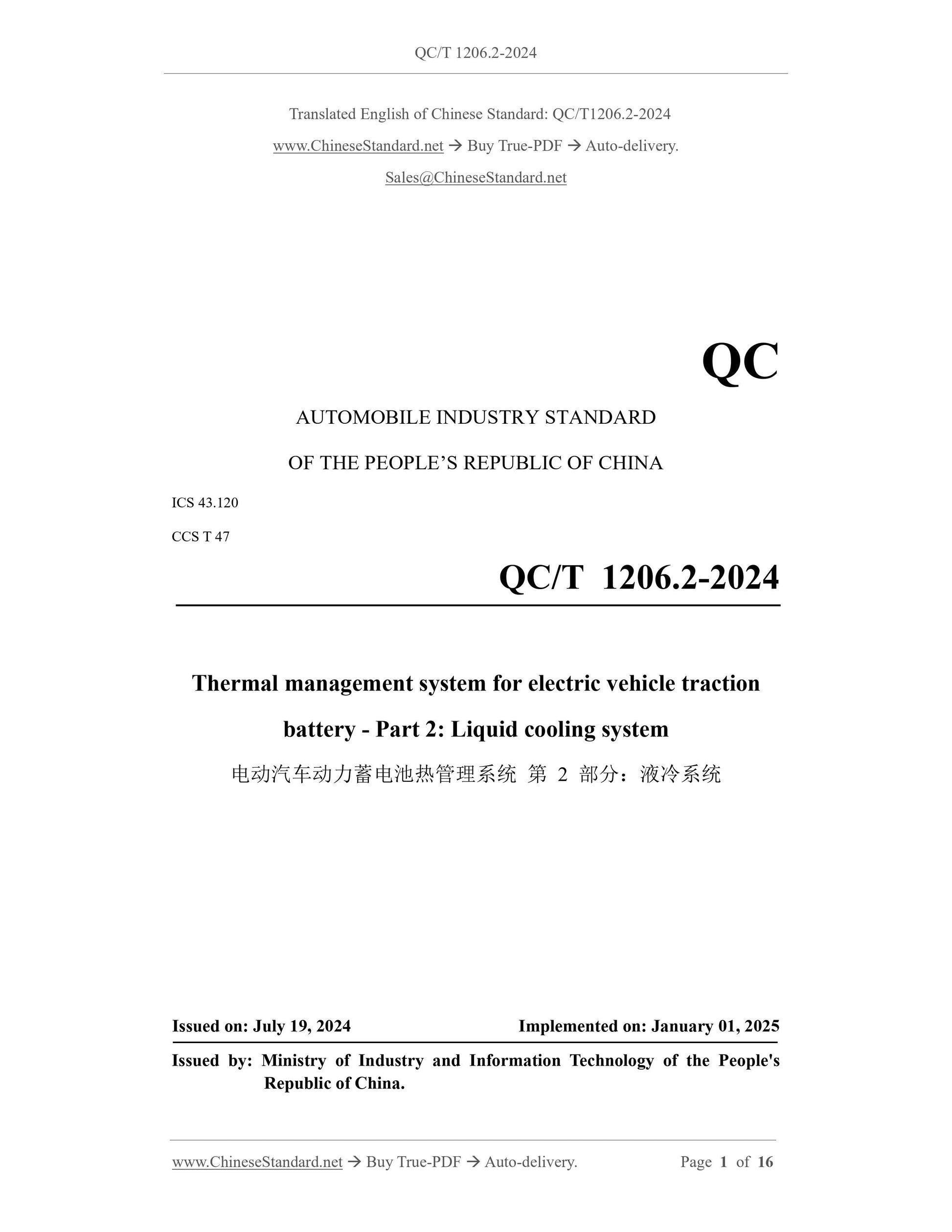
QC/T 1206.2-2024
QC
AUTOMOBILE INDUSTRY STANDARD
OF THE PEOPLE’S REPUBLIC OF CHINA
ICS 43.120
CCS T 47
Thermal management system for electric vehicle traction
battery - Part 2: Liquid cooling system
ISSUED ON: JULY 19, 2024
IMPLEMENTED ON: JANUARY 01, 2025
Issued by: Ministry of Industry and Information Technology of the People's
Republic of China.
Table of Contents
Foreword ... 3
Introduction ... 4
1 Scope ... 5
2 Normative references ... 5
3 Terms and definitions ... 5
4 Requirements ... 6
5 Test methods ... 9
6 Inspection rules ... 14
7 Labeling, packaging, transportation and storage ... 16
Thermal management system for electric vehicle traction
battery - Part 2: Liquid cooling system
1 Scope
This document specifies the technical requirements and test methods for liquid cooling
systems for electric vehicle power batteries (hereinafter referred to as "batteries").
This document is applicable to the research, development and testing of electric vehicle
power battery liquid cooling systems and their components.
2 Normative references
The following referenced documents are indispensable for the application of this
document. For dated references, only the edition cited applies. For undated references,
the latest edition of the referenced document (including any amendments) applies.
GB/T 2408-2021, Plastics -- Determination of burning characteristics -- Horizontal
and vertical test
GB/T 19596, Terminology of electric vehicles
GB 38031-2020, Electric vehicles traction battery safety requirements
QC/T 468-2010, Automobile radiator
QC/T 1206.1-2024, Thermal management system for electric vehicle traction battery
Part 1: General requirements
3 Terms and definitions
For the purposes of this document, the terms and definitions defined in GB/T 19596,
QC/T 1206.1-2024 as well as the followings apply.
3.1 liquid cooling system
A system that uses a coolant (such as a mixed solution of ethylene glycol and water) as
a heat exchange medium to cool the battery.
NOTE: It is generally composed of liquid cooling plate, liquid cooling pipe, joint, water inlet and
outlet assembly and other components, as shown in Figure 1.
After the flow resistance test is carried out in accordance with 5.4, the flow resistance
of the liquid cooling system shall meet the technical requirements specified by the
manufacturer.
4.3 Safety performance
4.3.1 Sealing
After the sealing test is carried out in accordance with 5.5, one of the following
requirements shall be met:
a) Wet test: no visible bubbles;
b) Dry test: leakage is no more than 2.5 mL/min;
c) Helium test: leakage rate is no more than 2×10⁻⁶ Pa•m3/s.
4.3.2 Flame retardancy
After the flame retardancy test is carried out in accordance with 5.6, the horizontal
combustion grade of non-metallic parts of the liquid cooling system shall meet the
requirements for grade HB in GB/T 2408-2021.
4.4 Technical requirements
4.4.1 Pressure resistance
After the pressure test according to 5.7, the liquid cooling system shall be leak-free.
The deformation in the deformation direction shall not exceed 10% of the original size.
4.4.2 Vibration
After the vibration test is carried out in accordance with 5.8, the liquid cooling system
shall meet the requirements of 4.3.1.
4.4.3 Welding strength
After the welding strength test is carried out in accordance with 5.9, there shall be no
damage or cracks at the joint welding.
4.4.4 Burst pressure
During the burst pressure test according to 5.10, the liquid cooling plate and liquid
cooling pipeline shall not be damaged or loose.
4.4.5 High and low temperature cycle
After the high and low temperature cycle test is carried out in accordance with 5.11, the
liquid cooling system shall meet the requirements of 4.3.1.
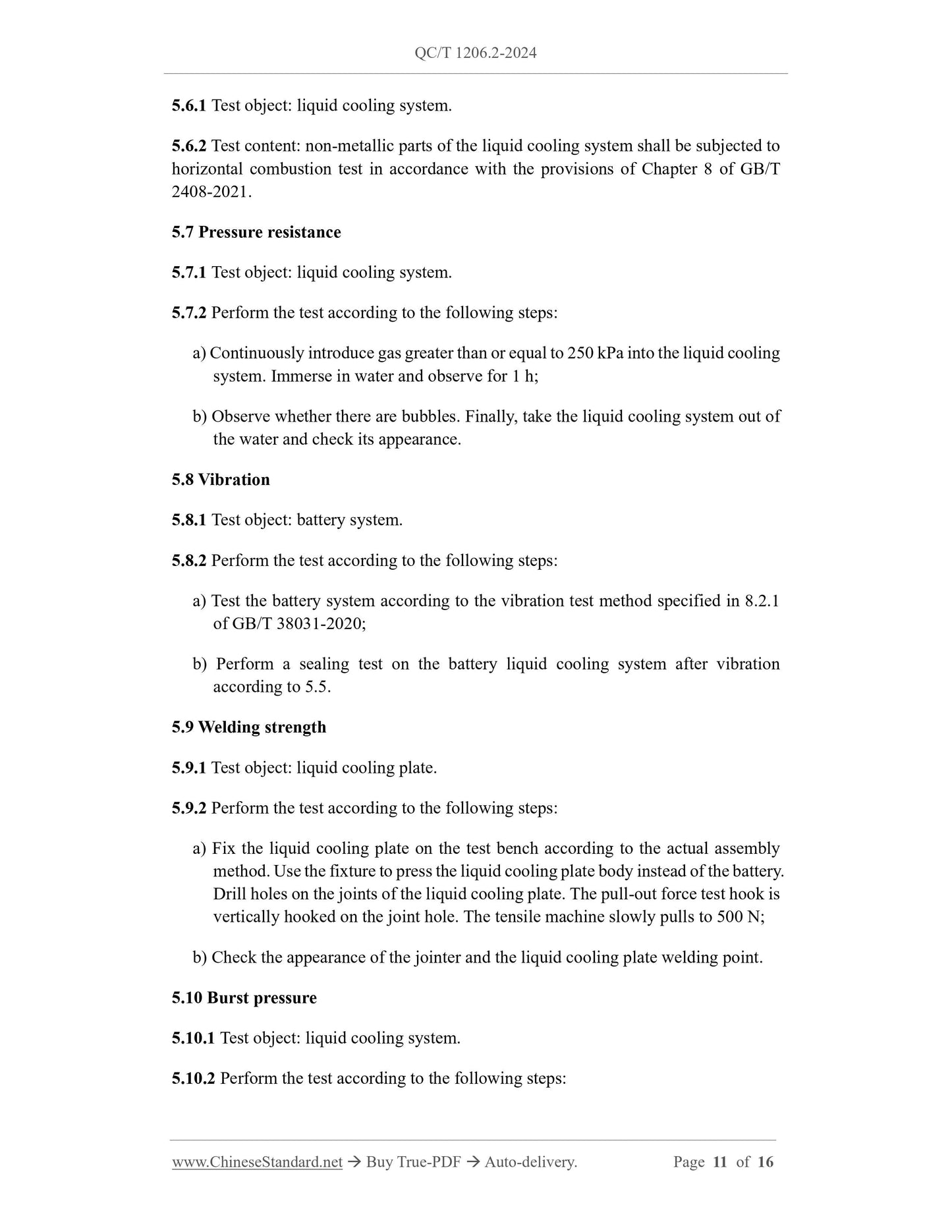
5.6.1 Test object: liquid cooling system.
5.6.2 Test content: non-metallic parts of the liquid cooling system shall be subjected to
horizontal combustion test in accordance with the provisions of Chapter 8 of GB/T
2408-2021.
5.7 Pressure resistance
5.7.1 Test object: liquid cooling system.
5.7.2 Perform the test according to the following steps:
a) Continuously introduce gas greater than or equal to 250 kPa into the liquid cooling
system. Immerse in water and observe for 1 h;
b) Observe whether there are bubbles. Finally, take the liquid cooling system out of
the water and check its appearance.
5.8 Vibration
5.8.1 Test object: battery system.
5.8.2 Perform the test according to the following steps:
a) Test the battery system according to the vibration test method specified in 8.2.1
of GB/T 38031-2020;
b) Perform a sealing test on the battery liquid cooling system after vibration
according to 5.5.
5.9 Welding strength
5.9.1 Test object: liquid cooling plate.
5.9.2 Perform the test according to the following steps:
a) Fix the liquid cooling plate on the test bench according to the actual assembly
method. Use the fixture to press the liquid cooling plate body instead of the battery.
Drill holes on the joints of the liquid cooling plate. The pull-out force test hook is
vertically hooked on the joint hole. The tensile machine slowly pulls to 500 N;
b) Check the appearance of the jointer and the liquid cooling plate welding point.
5.10 Burst pressure
5.10.1 Test object: liquid cooling system.
5.10.2 Perform the test according to the following steps:
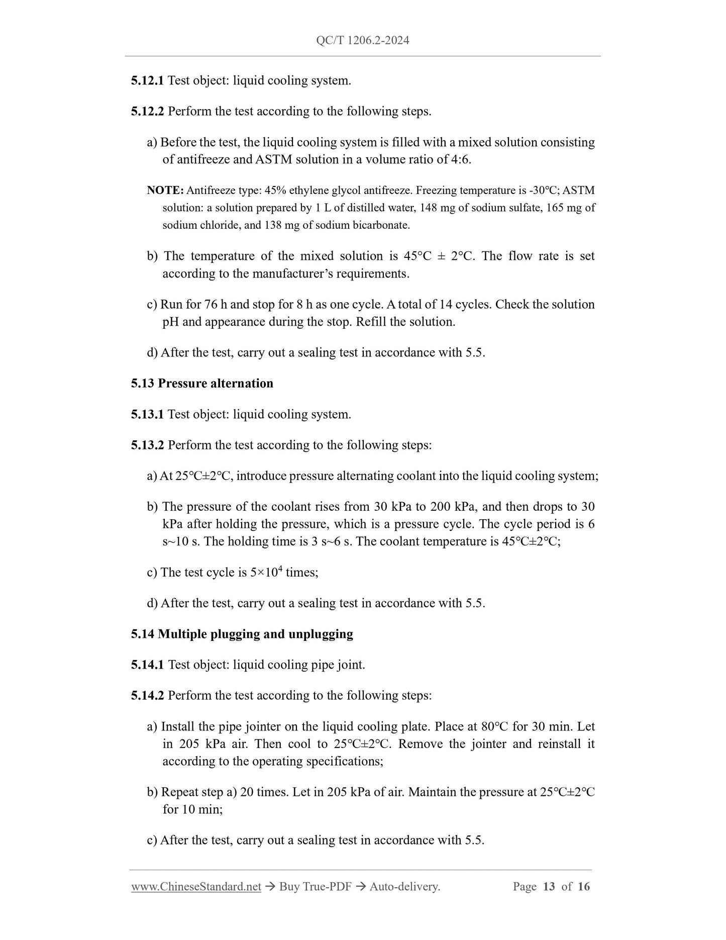
5.12.1 Test object: liquid cooling system.
5.12.2 Perform the test according to the following steps.
a) Before the test, the liquid cooling system is filled with a mixed solution consisting
of antifreeze and ASTM solution in a volume ratio of 4:6.
NOTE: Antifreeze type: 45% ethylene glycol antifreeze. Freezing temperature is -30℃; ASTM
solution: a solution prepared by 1 L of distilled water, 148 mg of sodium sulfate, 165 mg of
sodium chloride, and 138 mg of sodium bicarbonate.
b) The temperature of the mixed solution is 45°C ± 2°C. The flow rate is set
according to the manufacturer’s requirements.
c) Run for 76 h and stop for 8 h as one cycle. A total of 14 cycles. Check the solution
pH and appearance during the stop. Refill the solution.
d) After the test, carry out a sealing test in accordance with 5.5.
5.13 Pressure alternation
5.13.1 Test object: liquid cooling system.
5.13.2 Perform the test according to the following steps:
a) At 25℃±2℃, introduce pressure alternating coolant into the liquid cooling system;
b) The pressure of the coolant rises from 30 kPa to 200 kPa, and then drops to 30
kPa after holding the pressure, which is a pressure cycle. The cycle period is 6
s~10 s. The holding time is 3 s~6 s. The coolant temperature is 45℃±2℃;
c) The test cycle is 5×10⁴ times;
d) After the test, carry out a sealing test in accordance with 5.5.
5.14 Multiple plugging and unplugging
5.14.1 Test object: liquid cooling pipe joint.
5.14.2 Perform the test according to the following steps:
a) Install the pipe jointer on the liquid cooling plate. Place at 80℃ for 30 min. Let
in 205 kPa air. Then cool to 25℃±2℃. Remove the jointer and reinstall it
according to the operating specifications;
b) Repeat step a) 20 times. Let in 205 kPa of air. Maintain the pressure at 25℃±2℃
for 10 min;
c) After the test, carry out a sealing test in accordance with 5.5.
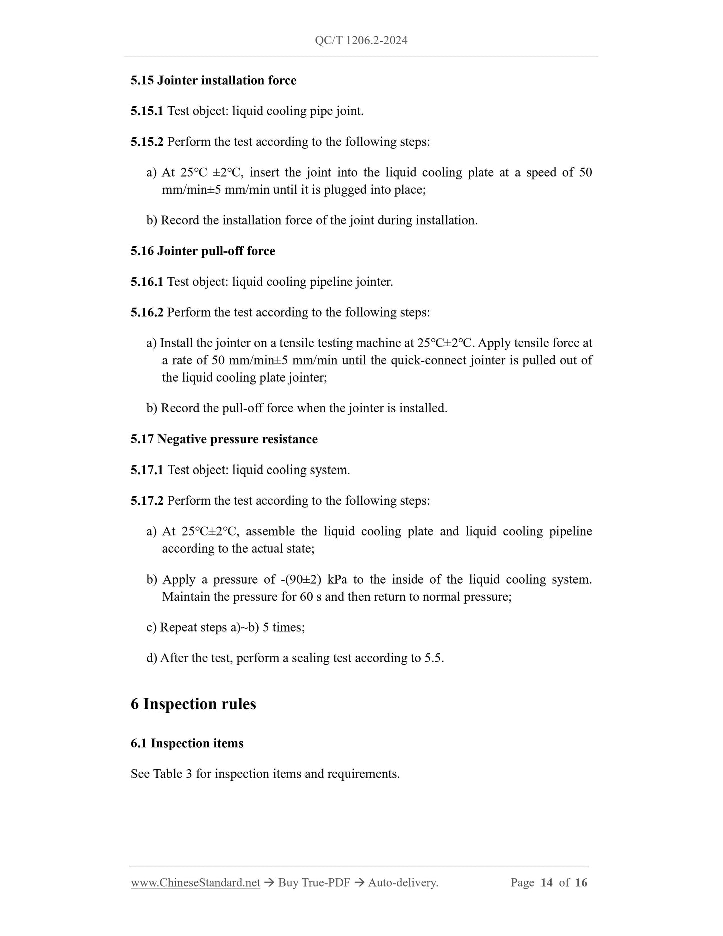
5.15 Jointer installation force
5.15.1 Test object: liquid cooling pipe joint.
5.15.2 Perform the test according to the following steps: