Skip to product information
1 of 6

PayPal, credit cards. Download editable-PDF and invoice in 1 second!

QC/T 1126-2019 English PDF (QCT1126-2019)

QC/T 1126-2019 English PDF (QCT1126-2019)

Regular price $220.00 USD
Regular price Sale price $220.00 USD
Sale Sold out
Shipping calculated at checkout.
Delivery: 3 seconds. Download true-PDF + Invoice.
Get Quotation: Click QC/T 1126-2019 (Self-service in 1-minute)
Historical versions (Master-website): QC/T 1126-2019
Preview True-PDF (Reload/Scroll-down if blank)

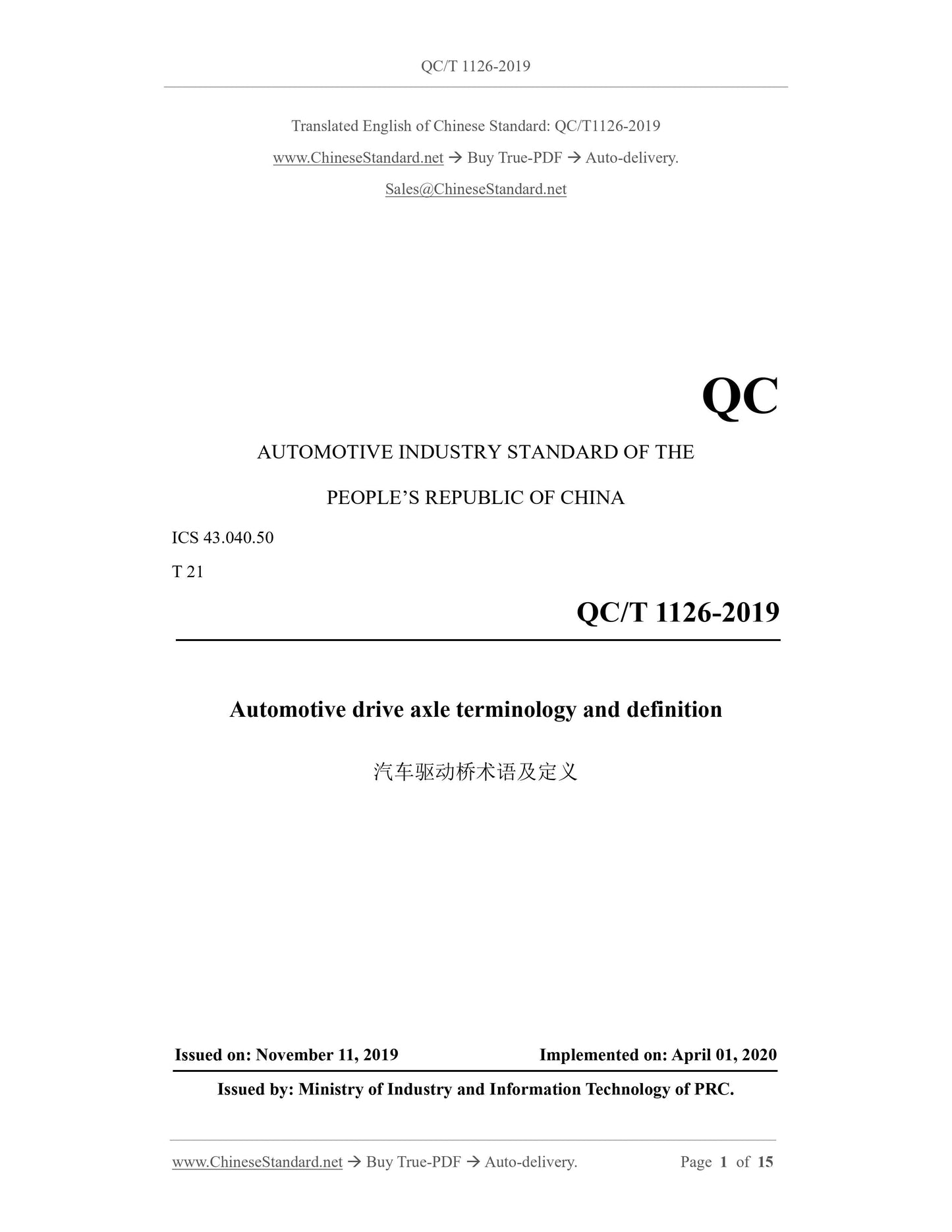
QC/T 1126-2019: Automotive drive axle terminology and definition
QC/T 1126-2019 English name.(Terms and definitions of automobile drive axle)
Automobile Industry Standard of the People's Republic of China
Terms and Definitions of Automobile Drive Axle
Released by the Ministry of Industry and Information Technology of the People's Republic of China
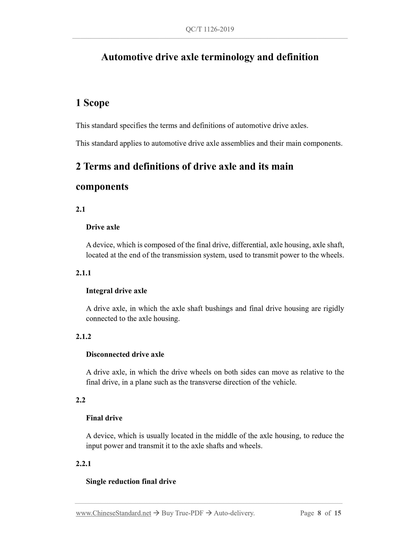
1 Scope
This standard specifies the terms and definitions of automotive drive axles.
This standard applies to automobile drive axle assemblies and their main components.
1 Scope
This standard specifies the terms and definitions of automotive drive axles.
This standard applies to automobile drive axle assemblies and their main components.
2 Terms and definitions of drive axle and its main components
2.1 drive axle drive axle
Composed of final drive, differential, axle housing and half shaft, it is located at the end of the drive train and is used to transmit power to the wheels.
2.1.1 integral drive axle
A drive axle in which both the half-shaft casing and the main reducer housing are rigidly connected to the axle housing.
2.1.2 Disconnected drive axle
The driving axle on both sides can move relative to the final drive in the transverse plane of the vehicle.
2.2 The final drive of the final drive
Usually located in the middle of the axle housing, it is a device that transmits the input power to reduce the speed to the half shaft and wheels.
2.2.1 single reduction final drive
The main reducer with only one pair of gear pairs for deceleration.
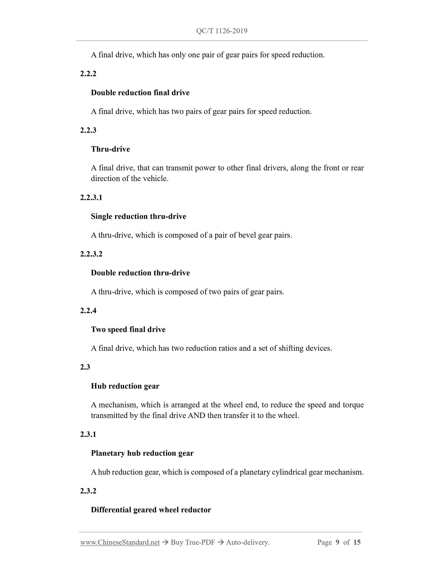
2.2.2 double reduction final drive
There are two pairs of gear pairs for the final reducer.
2.2.3 through-type main reducer thru-drive
The final drive that can transmit power to other final drives in front or rear of the car.
2.2.3.1 Single-stage through-type main reducer single reduction thru-drive
Through-type final reducer composed of a pair of bevel gear pairs.
2.2.3.2 double reduction thru-drive
Through-type main reducer composed of two pairs of gear pairs.
2.2.4 two speed final drive two speed final drive
A final drive with two reduction ratios and a set of shifting devices.
2.3 hub reduction gear
Arranged at the wheel end, the mechanism that transmits the speed and torque transmitted by the final drive to the wheels after decelerating and increasing the torque.
2.3.1 Planetary cylindrical wheel reducer planetary wheel reducer
A wheel speed reducer composed of a planetary spur gear mechanism.
2.3.2 Planetary bevel gear wheel reducer differential geared wheel reducer
A wheel speed reducer composed of a planetary bevel gear mechanism.
2.3.3 Spur geared wheel reducer with external meshing cylindrical gear
The wheel speed reducer is composed of external meshing cylindrical gear pair.
2.4 Differential differential
A mechanism that can make the left and right wheels of the same drive axle or two drive axles rotate at different speeds and transmit torque.
2.4.1 gear differential
A differential acting as a differential through a planetary gear mechanism.
2.4.1.1 bevel gear differential
A differential consisting of a planetary bevel gear mechanism.
2.4.1.2 spur gear differential
A differential made up of a planetary spur gear mechanism.
2.4.2 limited-slip differential
A differential that prevents the drive wheels from slipping.
2.4.2.1 Mandatory locking differential locking differential
Differential with locking mechanism.
2.4.2.2 self-locking differential
Differential that automatically locks on slippery surfaces.
2.4.2.2.1 friction disc self-locking differential multi-disc self-locking differential
A self-locking differential with friction plates in the bevel gear differential.
2.4.2.2.2 Automatic clutch type self-locking differential automotive positive locking differential
Self-locking differential with engaging clutch.
2.4.2.2.3 torsen differential
Differentials with special worm gears or parallel shafts.
2.4.2.2.4 Cam slider differential with side ring and radial cam plate
A differential consisting of inner and outer cams and sliders.
2.4.2.2.5 viscous coupling differential
Differential with silicone oil and inner and outer plates.
2.4.2.2.6 jaw differential
Differential with toothed inserts.
2.4.2.2.7 pitch differential
A differential with variable ratio gears.
2.4.2.2.8 Spiral bevel differential
Differential with spiral bevel gears.
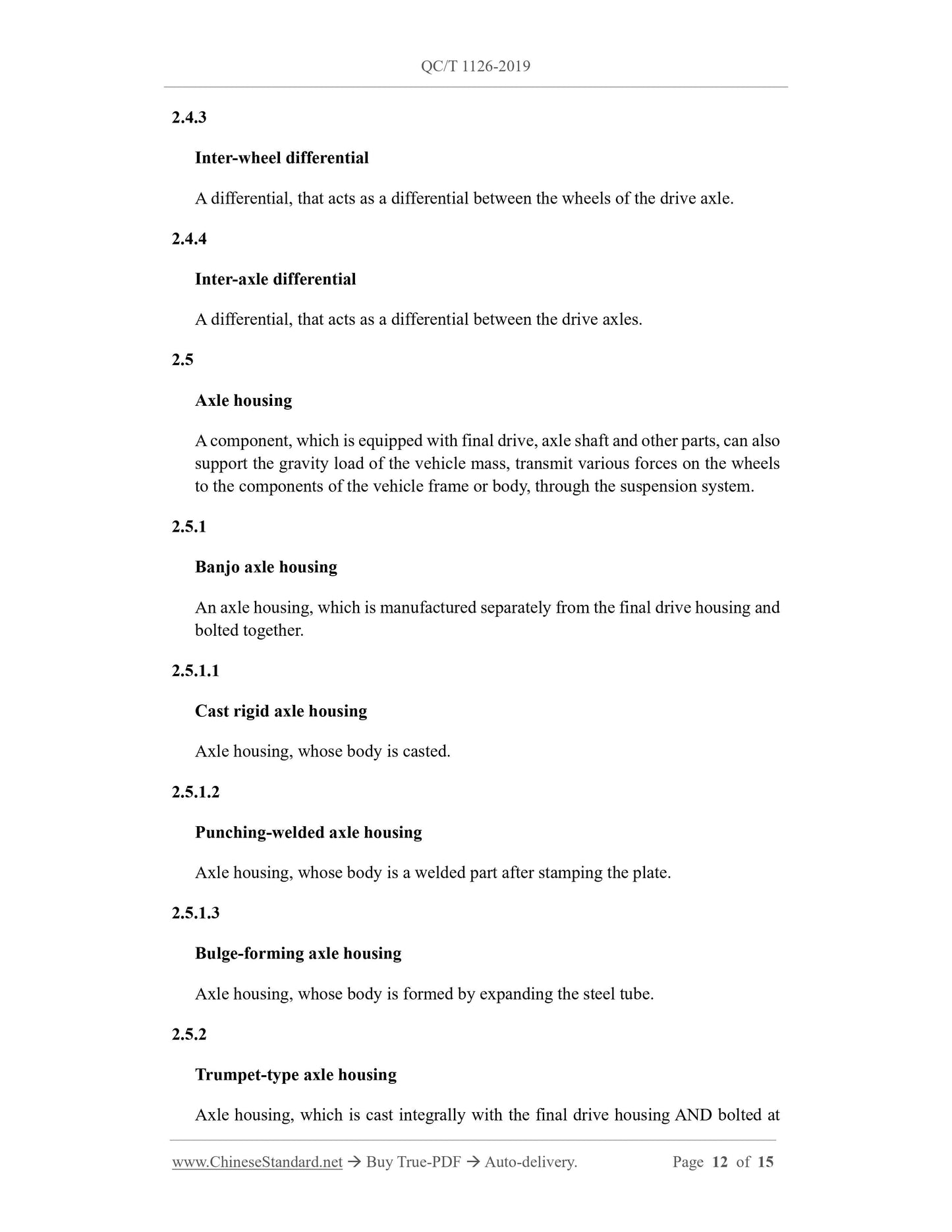
2.4.3 inter-wheel differential
A differential that acts as a differential between the drive axle wheels.
2.4.4 inter-axle differential
A differential that acts as a differential between drive axles.
2.5 axle housing axle housing
Installed with parts such as the main reducer and half shaft, it can also support the gravity load of the mass of the car, and transmit various forces on the wheels to the frame or body components through the suspension system.
2.5.1 Integral axle housing banjo axle housing
Axle housing manufactured separately from final drive housing and bolted together.
2.5.1.1 Cast rigid axle housing
The main body is the cast axle housing.
2.5.1.2 punching-welded axle housing
The main body is the axle housing of the welded part after sheet metal stamping.
2.5.1.3 bulge-forming axle housing
The main body is the axle housing of steel pipe expansion and forming parts.
2.5.2 Split-type axle housing trumpet-type axle housing
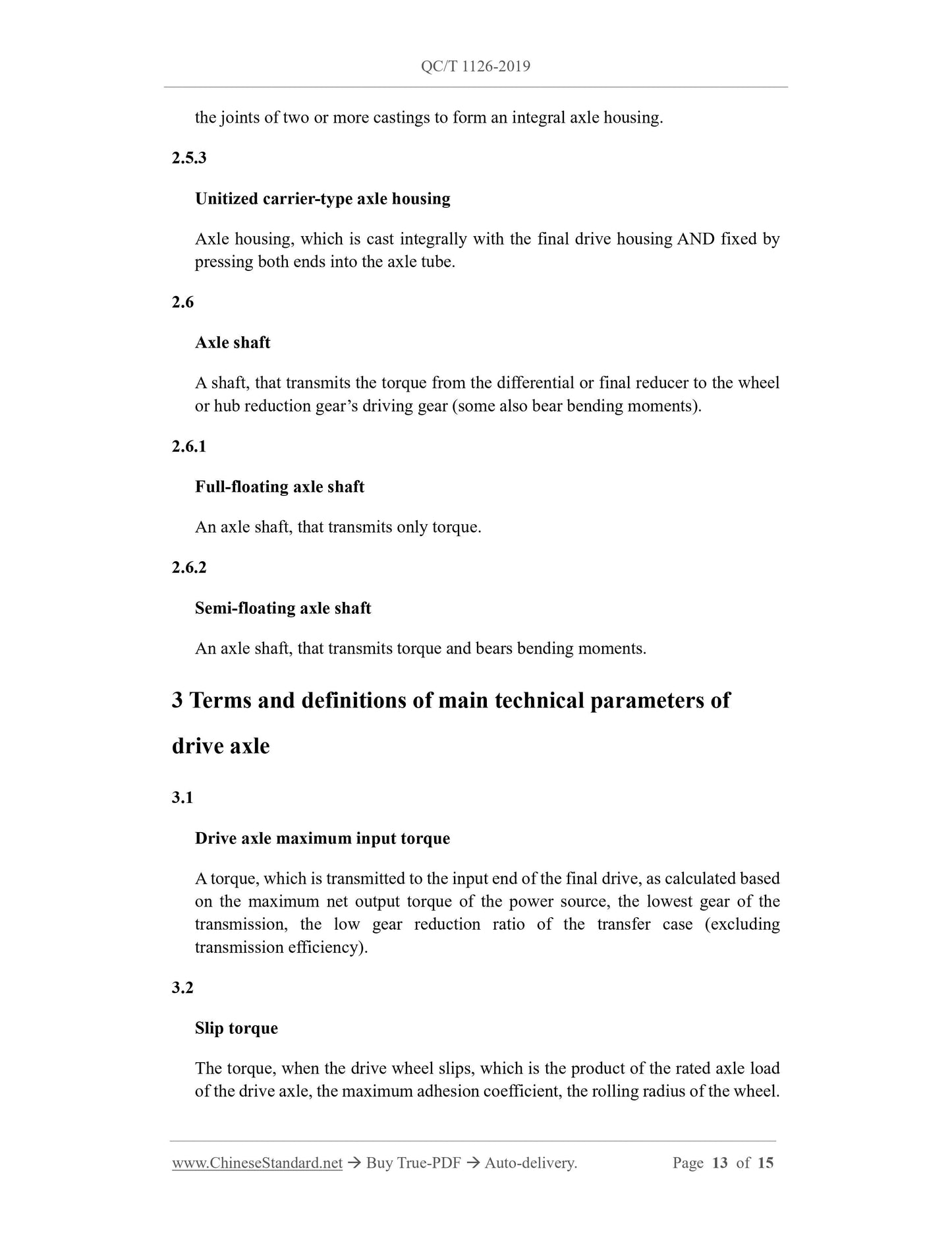
It is cast into one body with the main reducer housing and connected with bolts at the junction of two or more castings to form an integral axle housing.
2.5.3 unitized carrier-type axle housing
The axle housing is cast integrally with the main reducer housing, and the two ends are pressed into the shaft tube to fix the axle housing.
2.6 axle shaft
The shaft that transmits the torque from the differential or the final drive to the wheels or the driving gear of the wheel side reducer (some also bear the bending moment).
2.6.1 full-floating axle shaft
Half shafts that only transmit torque.
2.6.2 semi-floating axle shaft
A half shaft that transmits torque and receives bending moments.
3 Terms and Definitions of Main Technical Parameters of Drive Axle
3.1 drive axle maximum input torque drive axle maximum input torque
The torque transmitted to the input end of the main reducer calculated according to the maximum net output torque of the power source, the lowest gear of the transmission and the reduction ratio of the low gear of the transfer case (without considering the transmission efficiency).
3.2 Maximum adhesion torque slip torque of drive axle
The torque when the drive wheel is slipping is the product of the rated axle load of the drive axle, the maximum adhesion coefficient and the rolling radius of the wheel. 3.3
Drive axle rated axle load rated axle load
The bearing capacity of the drive axle specified by the manufacturer.
3.4 drive axle rated input torque drive axle rated input torque
Drive axle input torque specified by the manufacturer.
3.5 drive axle rated output torque drive axle rated output torque
Drive axle output torque specified by the manufacturer.
3.6 inter-wheel differential locking factor
The ratio of the torque of the slow-spinning wheels to the torque of the fast-spinning wheels.
3.7 inter-axle differential locking factor
The ratio of the torque of the slow turning axle to the torque of the fast turning axle.
3.8 drive axle ratio drive axle ratio
Under the condition of no differential speed, the ratio of the input shaft speed of the final drive to the wheel speed.
3.9 drive axle efficiency drive axle efficiency
The percentage value of drive axle output power and input power.
3.10 drive axle mass
Quality of the transaxle system excluding wheel assemblies and lubricating oil.

View full details