Skip to product information
1 of 12

PayPal, credit cards. Download editable-PDF & invoice in 1 second!

QC/T 1112-2019 English PDF (QCT1112-2019)

QC/T 1112-2019 English PDF (QCT1112-2019)

Regular price $235.00 USD
Regular price Sale price $235.00 USD
Sale Sold out
Shipping calculated at checkout.
Delivery: 3 seconds. Download true-PDF + Invoice.
Get QUOTATION in 1-minute: Click QC/T 1112-2019
Historical versions: QC/T 1112-2019
Preview True-PDF (Reload/Scroll if blank)

QC/T 1112-2019: Passenger cars-biaxial fatigue test method for wheels
QC/T 1112-2019
QC
AUTOMOBILE INDUSTRY STANDARD
OF THE PEOPLE’S REPUBLIC OF CHINA
ICS 43.040.50
T 22
Passenger cars - Biaxial fatigue test method for wheels
ISSUED ON: NOVEMBER 11, 2019
IMPLEMENTED ON: APRIL 01, 2020
Issued by: Ministry of Industry and Information Technology of PRC
Table of Contents
Foreword ... 7
1 Scope ... 8
2 Normative references ... 8
3 Terms and definitions ... 8
4 Test equipment ... 9
5 Test wheels ... 11
6 Determination of wheel load sequence ... 11
7 Test method ... 13
8 Termination of the test ... 14
Appendix A (Normative) Inner rim pre-damage test method ... 15
Passenger cars - Biaxial fatigue test method for wheels
1 Scope
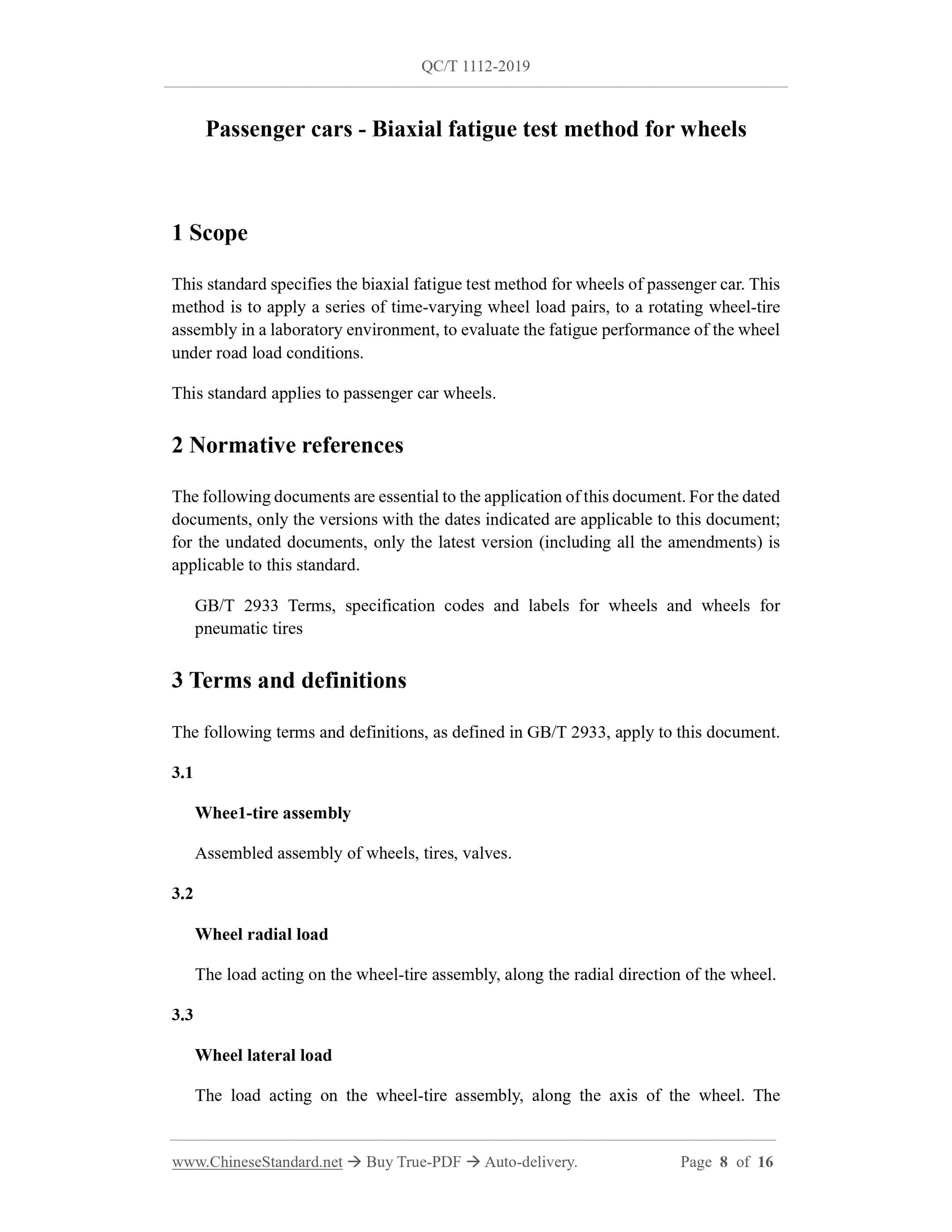
This standard specifies the biaxial fatigue test method for wheels of passenger car. This
method is to apply a series of time-varying wheel load pairs, to a rotating wheel-tire
assembly in a laboratory environment, to evaluate the fatigue performance of the wheel
under road load conditions.
This standard applies to passenger car wheels.
2 Normative references
The following documents are essential to the application of this document. For the dated
documents, only the versions with the dates indicated are applicable to this document;
for the undated documents, only the latest version (including all the amendments) is
applicable to this standard.
GB/T 2933 Terms, specification codes and labels for wheels and wheels for
pneumatic tires
3 Terms and definitions
The following terms and definitions, as defined in GB/T 2933, apply to this document.
3.1
Whee1-tire assembly
Assembled assembly of wheels, tires, valves.
3.2
Wheel radial load
The load acting on the wheel-tire assembly, along the radial direction of the wheel.
3.3
Wheel lateral load
The load acting on the wheel-tire assembly, along the axis of the wheel. The
direction pointing to the inner side of the rim is positive; otherwise, it is negative, as
shown in Figure 1 and Figure 2.
3.4
Wheel load pair
The combination of a pair of radial and lateral loads, which act simultaneously on
the wheel-tire assembly.
3.5
Wheel load sequence
It is composed of wheel load pair sequence, including such factors as wheel load
pair and the corresponding test mileage, etc.
3.6
Whee1 camber ang1e
In a biaxial fatigue test, the camber angle is the angle, which is formed by the center
plane of the wheel rim and the normal to the tangential plane of the tire drum.
As shown in Figure 1 and Figure 2, cambering inside is positive, cambering outside
is negative.
3.7
Wheel slip ang1e
In the biaxial fatigue test, the wheel slip angle is the slip angle of the center plane of
the wheel rim, with the radial load acting line as the axis, as shown in Figure 1.
When the lateral load is positive, the slip angle is positive; otherwise, it is negative.
3.8
Curb
On the inner drum biaxial fatigue testing machine, the annular device which is
installed on the inner surface of the drum to apply lateral load to the wheel, as shown
in Figure 2.
4 Test equipment
4.1 General equipment requirements
7 Test method
7.1 Select the tires, which are specified by the entrusted testing agency.
7.2 Install tires on the wheels and inflate them. The recommended inflation pressure is
450 kPa ± 10 kPa.
7.3 Perform dynamic balance correction on the test wheel-tire assembly. The remaining
unbalanced mass of the inner and outer sides should be controlled within 5 g.
7.4 For aluminum alloy wheels, the inner rim of the wheel shall be pre-damaged before
the test; the method shall be in accordance with Appendix A.
7.5 Adjust the inflation pressure of the pre-damaged aluminum alloy wheel-tire
assembly to 450 kPa ± 10 kPa.
7.6 Adjust the test equipment, according to the requirements in Chapter 4. When
choosing an inner drum testing machine, it should choose the drum, according to the
principle that the outer diameter of the tire is 60% ~ 80% of the inner diameter of the
drum.
7.7 Install the wheel-tire assembly on the biaxial fatigue testing machine. The fixing
device of the wheel on the testing machine shall be equivalent in size to the fixing
device used on the vehicle. Tighten the bolts or nuts to the specified torque value, when
loading the vehicle. If there is no specification, the recommended tightening torque is
120 N·m ± 10 N·m.
7.8 Input the test parameters and wheel load sequence on the biaxial test equipment.
The recommended surface linear speed of the drum is 105 km/h.
7.9 Adjust the safety protection limit, to carry out the load spectrum test run, to confirm
that the wheel-tire assembly can operate normally, under each correct test load pair.
7.10 Run the test load sequence cyclically on the test equipment, to test the wheel-tire
assembly. It is recommended to stop when running to 100 km; continue the test after
checking the bolt torque. During the test, if the tire is damaged or the bolt is broken, the
test can be continued after replacement.
7.11 After completing the specified test mileage, inspect the wheel using the dye
penetrant method.
Note: The specified test mileage is set by the wheel or vehicle manufacturer, according to the
service requirements of the wheel.

View full details