www.ChineseStandard.us -- Field Test Asia Pte. Ltd.
NB/T 47013.14-2023: Nondestructive testing of pressure equipment - Part 14: X-ray computed radiographic testing
Delivery: 9 seconds. Download (and Email) true-PDF + Invoice.
Get Quotation: Click
NB/T 47013.14-2023 (Self-service in 1-minute)
Newer / historical versions: NB/T 47013.14-2023Preview True-PDF
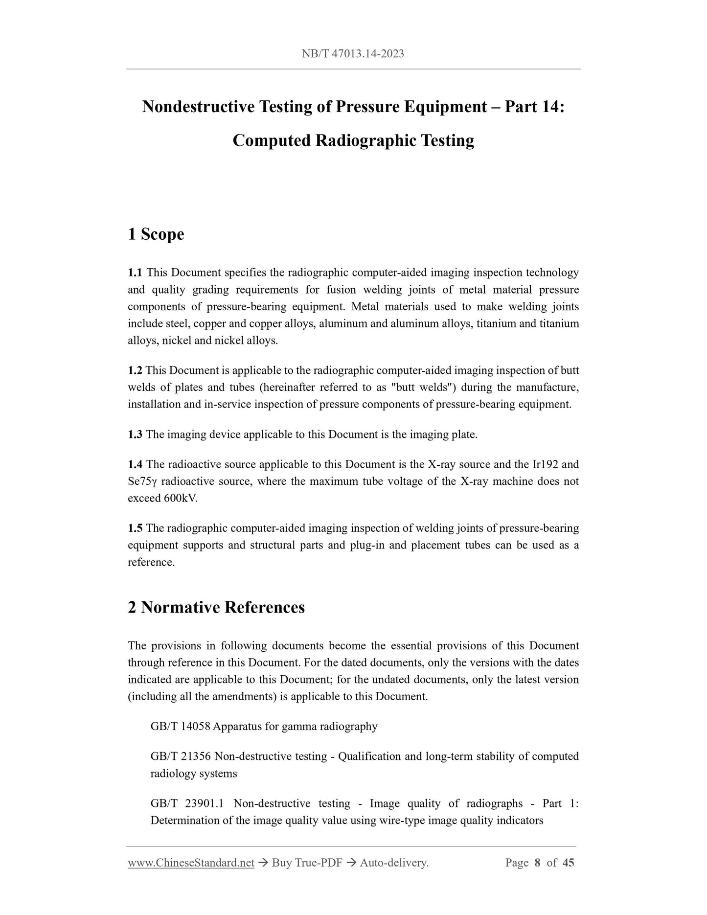
Scope
1.1 This Document specifies the radiographic computer-aided imaging inspection technology
and quality grading requirements for fusion welding joints of metal material pressure
components of pressure-bearing equipment. Metal materials used to make welding joints
include steel, copper and copper alloys, aluminum and aluminum alloys, titanium and titanium
alloys, nickel and nickel alloys.
1.2 This Document is applicable to the radiographic computer-aided imaging inspection of butt
welds of plates and tubes (hereinafter referred to as "butt welds") during the manufacture,
installation and in-service inspection of pressure components of pressure-bearing equipment.
1.3 The imaging device applicable to this Document is the imaging plate.
1.4 The radioactive source applicable to this Document is the X-ray source and the Ir192 and
Se75γ radioactive source, where the maximum tube voltage of the X-ray machine does not
exceed 600kV.
1.5 The radiographic computer-aided imaging inspection of welding joints of pressure-bearing
equipment supports and structural parts and plug-in and placement tubes can be used as a
reference.
Basic Data
| Standard ID | NB/T 47013.14-2023 (NB/T47013.14-2023) |
| Description (Translated English) | Nondestructive testing of pressure equipment - Part 14: X-ray computed radiographic testing |
| Sector / Industry | Energy Industry Standard (Recommended) |
| Classification of Chinese Standard | H26 |
| Classification of International Standard | 77.040.20 |
| Word Count Estimation | 33,327 |
| Date of Issue | 2023-10-11 |
| Date of Implementation | 2024-04-11 |
| Older Standard (superseded by this standard) | NB/T 47013.14-2016 |
| Issuing agency(ies) | National Energy Administration |