Skip to product information
1 of 12

PayPal, credit cards. Download editable-PDF and invoice in 1 second!

NB/T 42107-2017 English PDF (NBT42107-2017)

NB/T 42107-2017 English PDF (NBT42107-2017)

Regular price $410.00 USD
Regular price Sale price $410.00 USD
Sale Sold out
Shipping calculated at checkout.
Delivery: 3 seconds. Download true-PDF + Invoice.
Get QUOTATION in 1-minute: Click NB/T 42107-2017
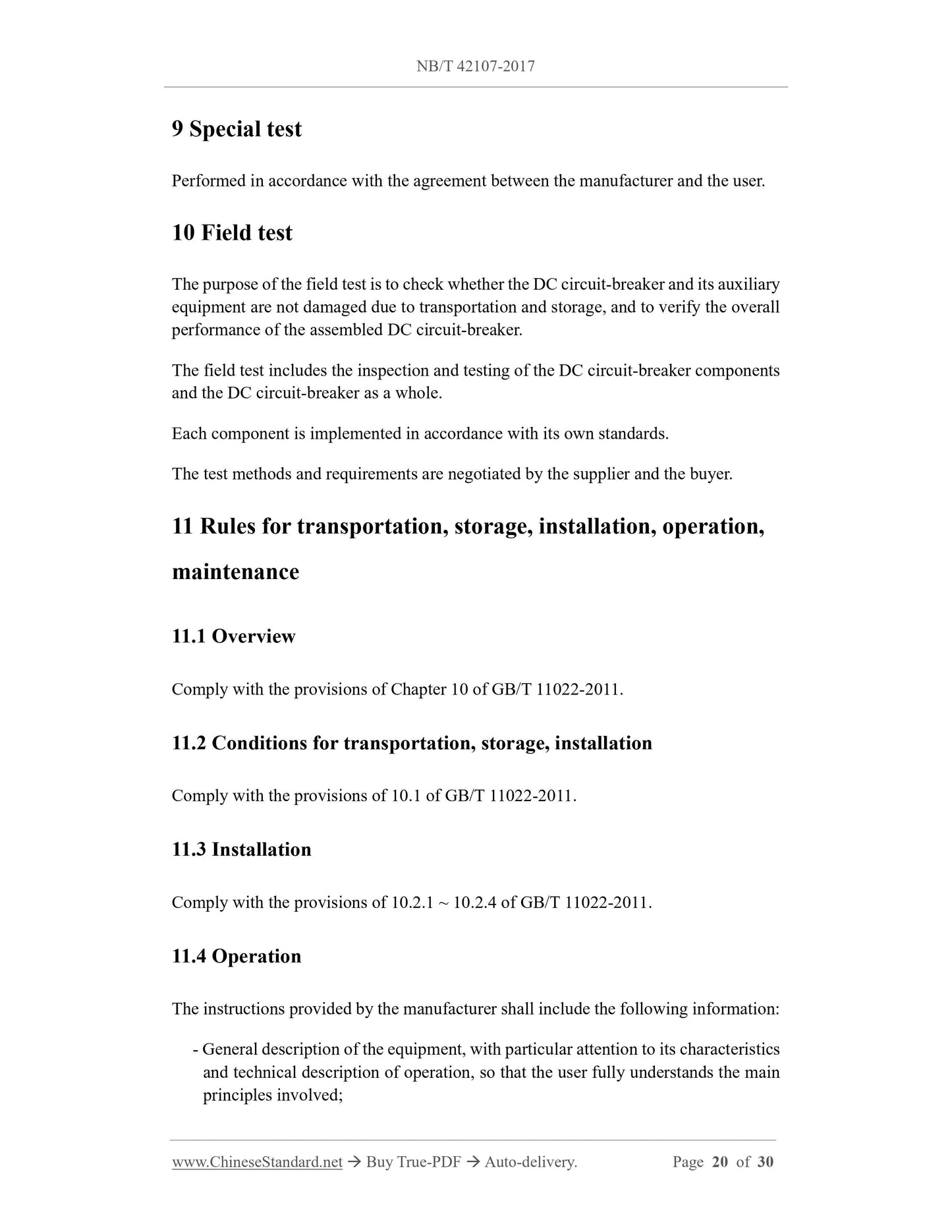
Historical versions: NB/T 42107-2017
Preview True-PDF (Reload/Scroll if blank)

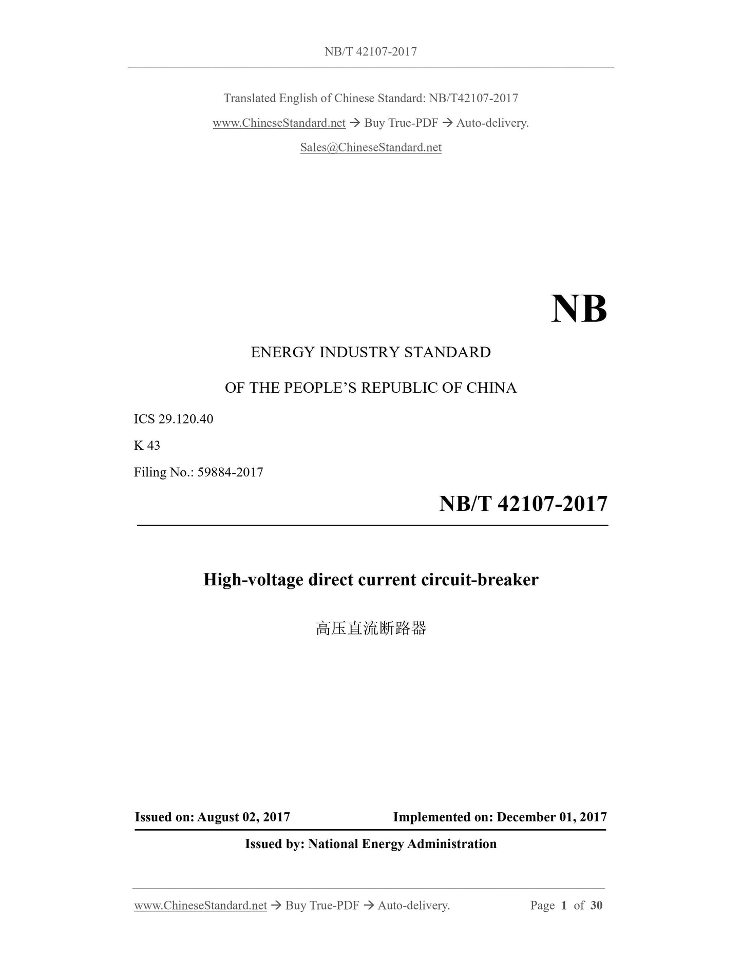
NB/T 42107-2017: High-voltage direct current circuit-breaker
NB/T 42107-2017
NB
ENERGY INDUSTRY STANDARD
ICS 29.120.40
K 43
Filing No.. 59884-2017
High-voltage direct current circuit-breaker
高压直流断路器
ISSUED ON. AUGUST 02, 2017
IMPLEMENTED ON. DECEMBER 01, 2017
Issued by. National Energy Administration
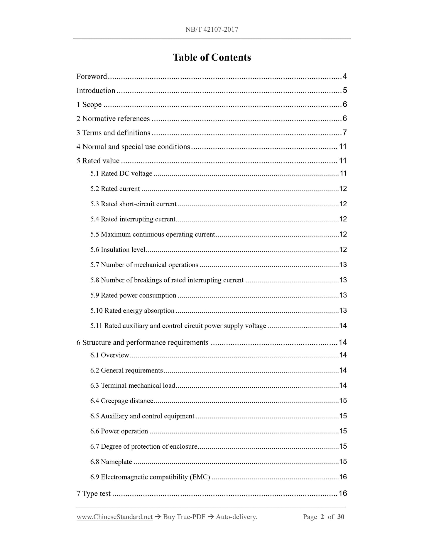
Table of Contents
Foreword... 4
Introduction... 5
1 Scope... 6
2 Normative references... 6
3 Terms and definitions... 7
4 Normal and special use conditions... 11
5 Rated value... 11
5.1 Rated DC voltage... 11
5.2 Rated current... 12
5.3 Rated short-circuit current... 12
5.4 Rated interrupting current... 12
5.5 Maximum continuous operating current... 12
5.6 Insulation level... 12
5.7 Number of mechanical operations... 13
5.8 Number of breakings of rated interrupting current... 13
5.9 Rated power consumption... 13
5.10 Rated energy absorption... 13
5.11 Rated auxiliary and control circuit power supply voltage... 14
6 Structure and performance requirements... 14
6.1 Overview... 14
6.2 General requirements... 14
6.3 Terminal mechanical load... 14
6.4 Creepage distance... 15
6.5 Auxiliary and control equipment... 15
6.6 Power operation... 15
6.7 Degree of protection of enclosure... 15
6.8 Nameplate... 15
6.9 Electromagnetic compatibility (EMC)... 16
7 Type test... 16
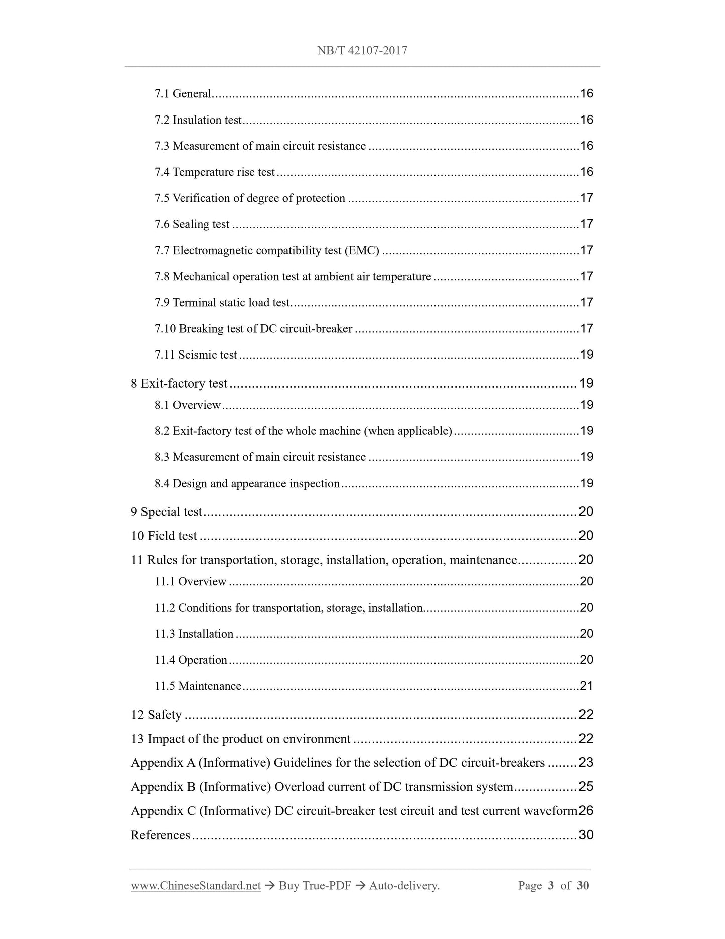
7.1 General... 16
7.2 Insulation test... 16
7.3 Measurement of main circuit resistance... 16
7.4 Temperature rise test... 16
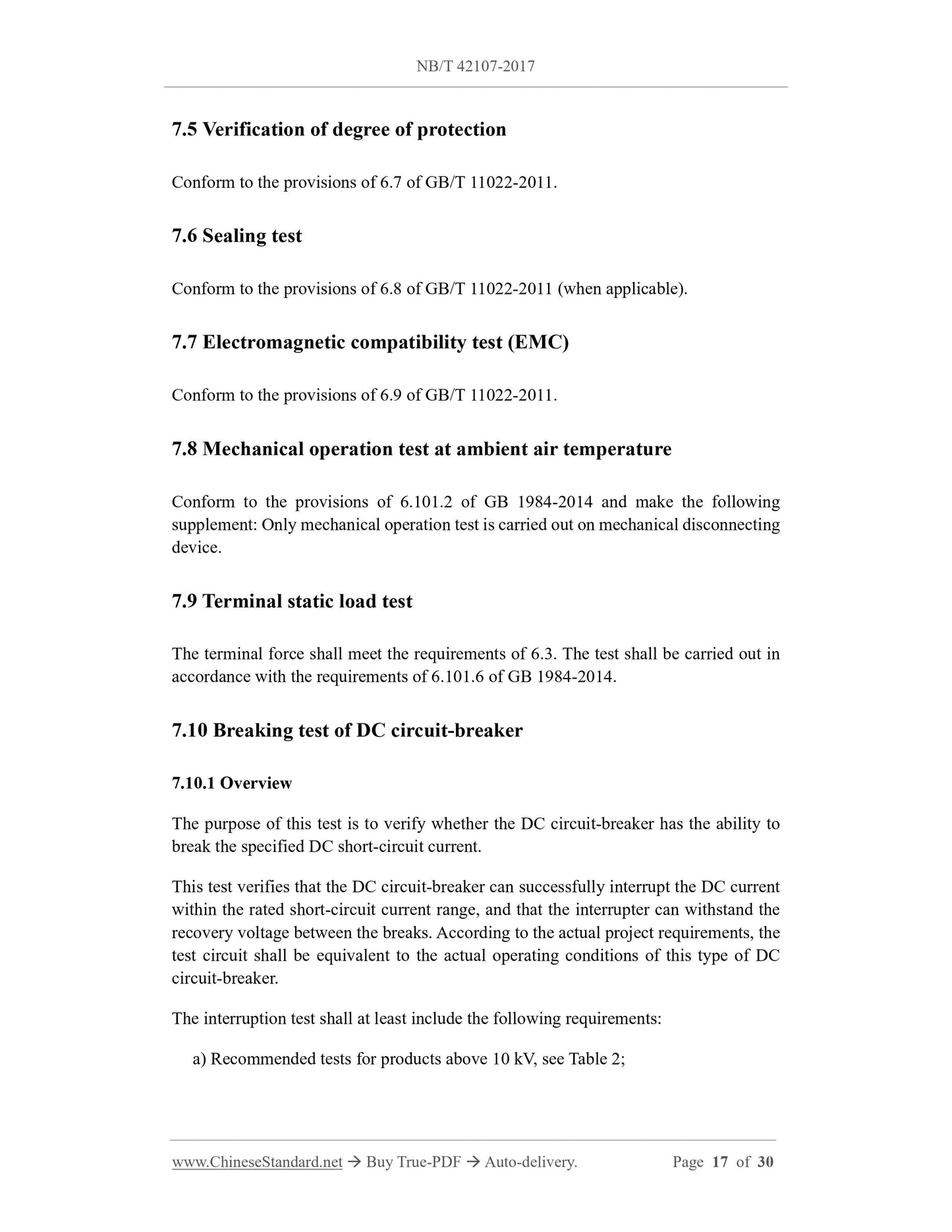
7.5 Verification of degree of protection... 17
7.6 Sealing test... 17
7.7 Electromagnetic compatibility test (EMC)... 17
7.8 Mechanical operation test at ambient air temperature... 17
7.9 Terminal static load test... 17
7.10 Breaking test of DC circuit-breaker... 17
7.11 Seismic test... 19
8 Exit-factory test... 19
8.1 Overview... 19
8.2 Exit-factory test of the whole machine (when applicable)... 19
8.3 Measurement of main circuit resistance... 19
8.4 Design and appearance inspection... 19
9 Special test... 20
10 Field test... 20
11 Rules for transportation, storage, installation, operation, maintenance... 20
11.1 Overview... 20
11.2 Conditions for transportation, storage, installation... 20
11.3 Installation... 20
11.4 Operation... 20
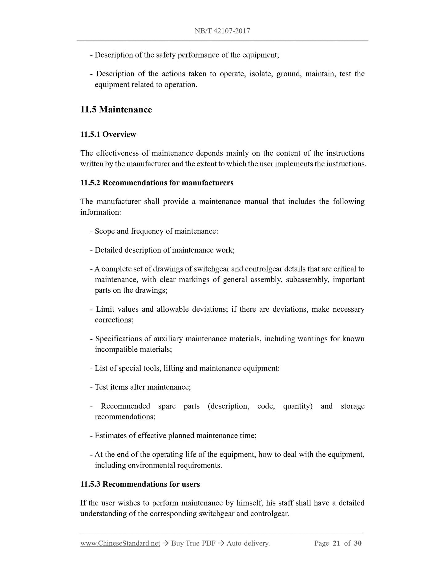
11.5 Maintenance... 21
12 Safety... 22
13 Impact of the product on environment... 22
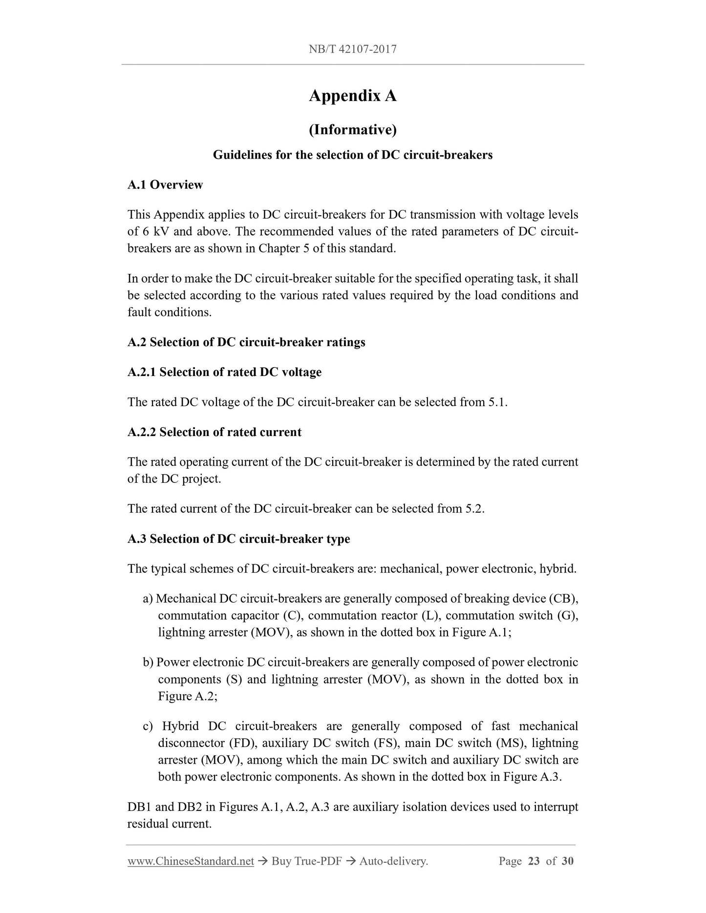
Appendix A (Informative) Guidelines for the selection of DC circuit-breakers... 23
Appendix B (Informative) Overload current of DC transmission system... 25
Appendix C (Informative) DC circuit-breaker test circuit and test current waveform 26
References... 30
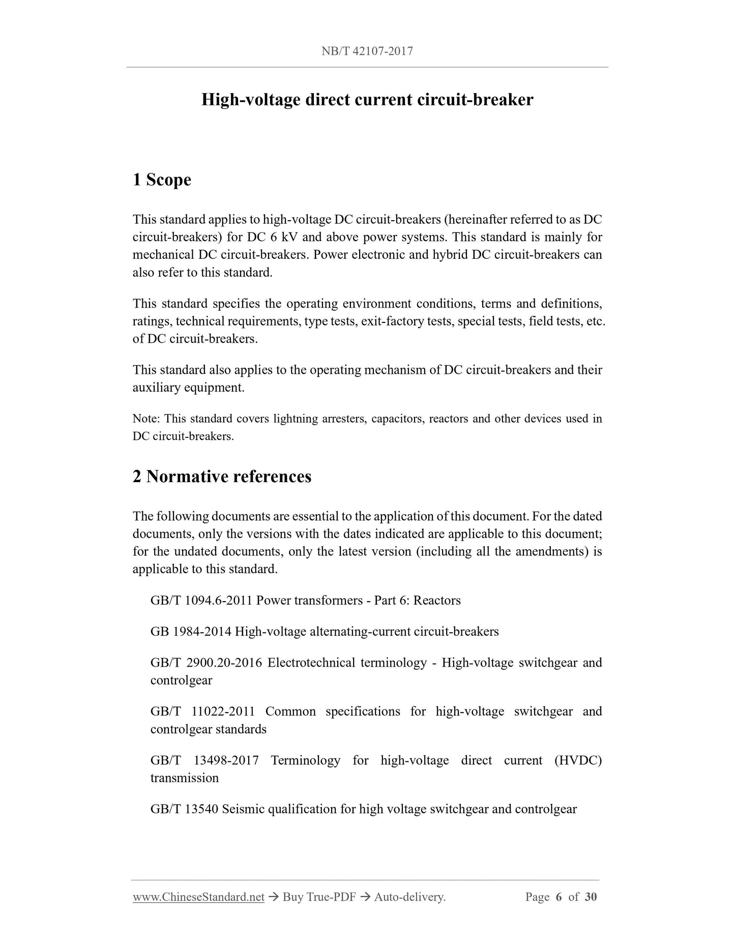
High-voltage direct current circuit-breaker
1 Scope
This standard applies to high-voltage DC circuit-breakers (hereinafter referred to as DC
circuit-breakers) for DC 6 kV and above power systems. This standard is mainly for
mechanical DC circuit-breakers. Power electronic and hybrid DC circuit-breakers can
also refer to this standard.
This standard specifies the operating environment conditions, terms and definitions,
ratings, technical requirements, type tests, exit-factory tests, special tests, field tests, etc.
of DC circuit-breakers.
This standard also applies to the operating mechanism of DC circuit-breakers and their
auxiliary equipment.
Note. This standard covers lightning arresters, capacitors, reactors and other devices used in
DC circuit-breakers.
2 Normative references
The following documents are essential to the application of this document. For the dated
documents, only the versions with the dates indicated are applicable to this document;
for the undated documents, only the latest version (including all the amendments) is
applicable to this standard.
GB/T 1094.6-2011 Power transformers - Part 6.Reactors
GB 1984-2014 High-voltage alternating-current circuit-breakers
GB/T 2900.20-2016 Electrotechnical terminology - High-voltage switchgear and
controlgear
GB/T 11022-2011 Common specifications for high-voltage switchgear and
controlgear standards
GB/T 13498-2017 Terminology for high-voltage direct current (HVDC)
transmission
GB/T 13540 Seismic qualification for high voltage switchgear and controlgear
Note. Where there are special requirements for DC voltage, it shall be determined by
negotiation between the supplier and the buyer.
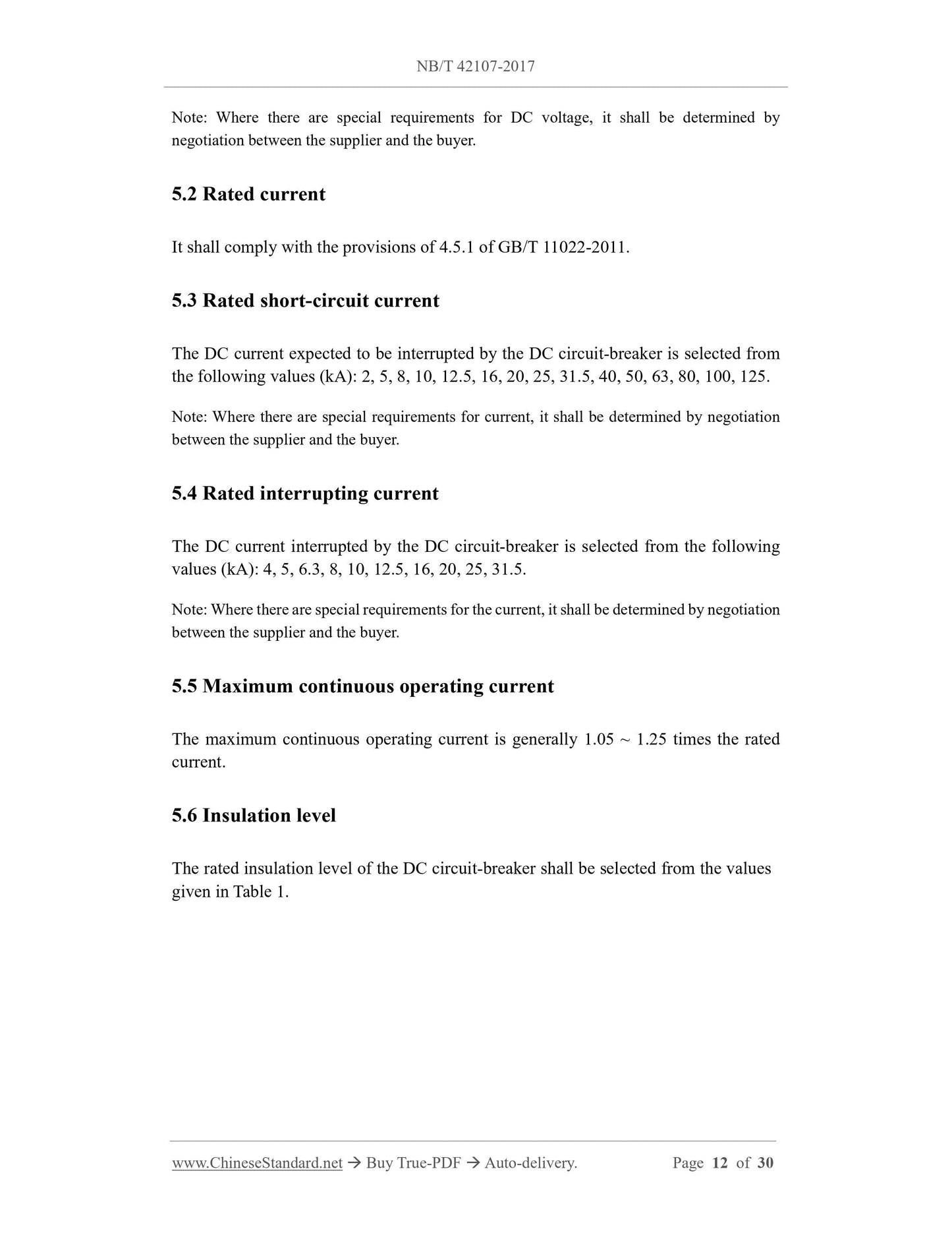
5.2 Rated current
It shall comply with the provisions of 4.5.1 of GB/T 11022-2011.
5.3 Rated short-circuit current
The DC current expected to be interrupted by the DC circuit-breaker is selected from
the following values (kA). 2, 5, 8, 10, 12.5, 16, 20, 25, 31.5, 40, 50, 63, 80, 100, 125.
Note. Where there are special requirements for current, it shall be determined by negotiation
between the supplier and the buyer.
5.4 Rated interrupting current
The DC current interrupted by the DC circuit-breaker is selected from the following
values (kA). 4, 5, 6.3, 8, 10, 12.5, 16, 20, 25, 31.5.
Note. Where there are special requirements for the current, it shall be determined by negotiation
between the supplier and the buyer.
5.5 Maximum continuous operating current
The maximum continuous operating current is generally 1.05 ~ 1.25 times the rated
current.
5.6 Insulation level
The rated insulation level of the DC circuit-breaker shall be selected from the values
given in Table 1.
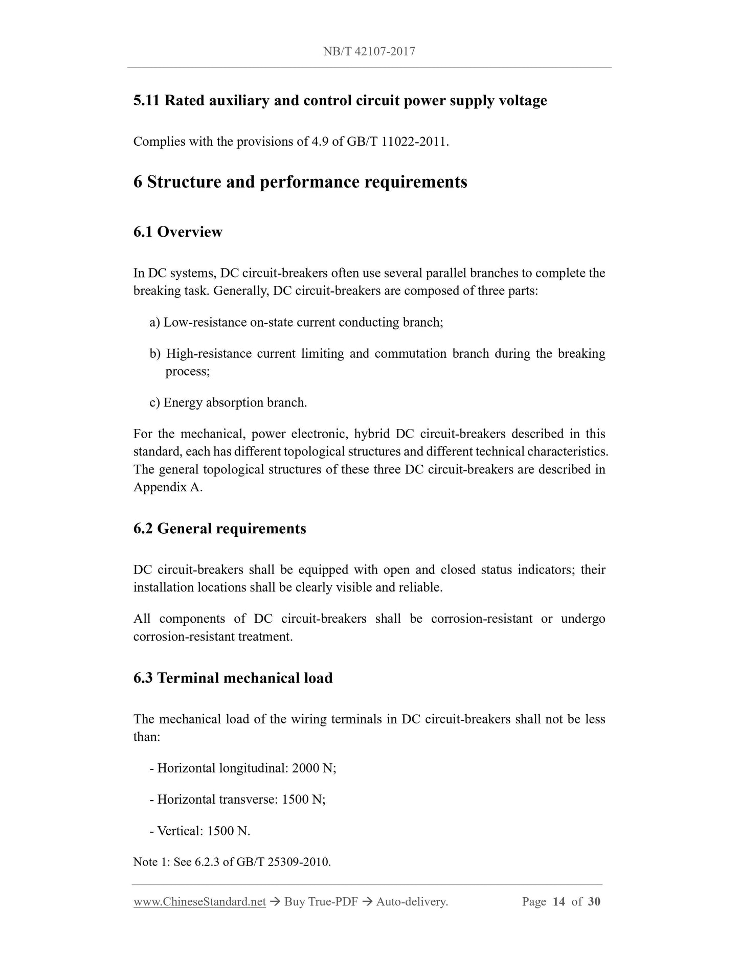
5.11 Rated auxiliary and control circuit power supply voltage
Complies with the provisions of 4.9 of GB/T 11022-2011.
6 Structure and performance requirements
6.1 Overview
In DC systems, DC circuit-breakers often use several parallel branches to complete the
breaking task. Generally, DC circuit-breakers are composed of three parts.
a) Low-resistance on-state current conducting branch;
b) High-resistance current limiting and commutation branch during the breaking
process;
c) Energy absorption branch.
For the mechanical, power electronic, hybrid DC circuit-breakers described in this
standard, each has different topological structures and different technical characteristics.
The general topological structures of these three DC circuit-breakers are described in
Appendix A.
6.2 General requirements
DC circuit-breakers shall be equipped with open and closed status indicators; their
installation locations shall be clearly visible and reliable.
All components of DC circuit-breakers shall be corrosion-resistant or undergo
corrosion-resistant treatment.
6.3 Terminal mechanical load
The mechanical load of the wiring terminals in DC circuit-breakers shall not be less
than.
- Horizontal longitudinal. 2000 N;
- Horizontal transverse. 1500 N;
- Vertical. 1500 N.
Note 1.See 6.2.3 of GB/T 25309-2010.
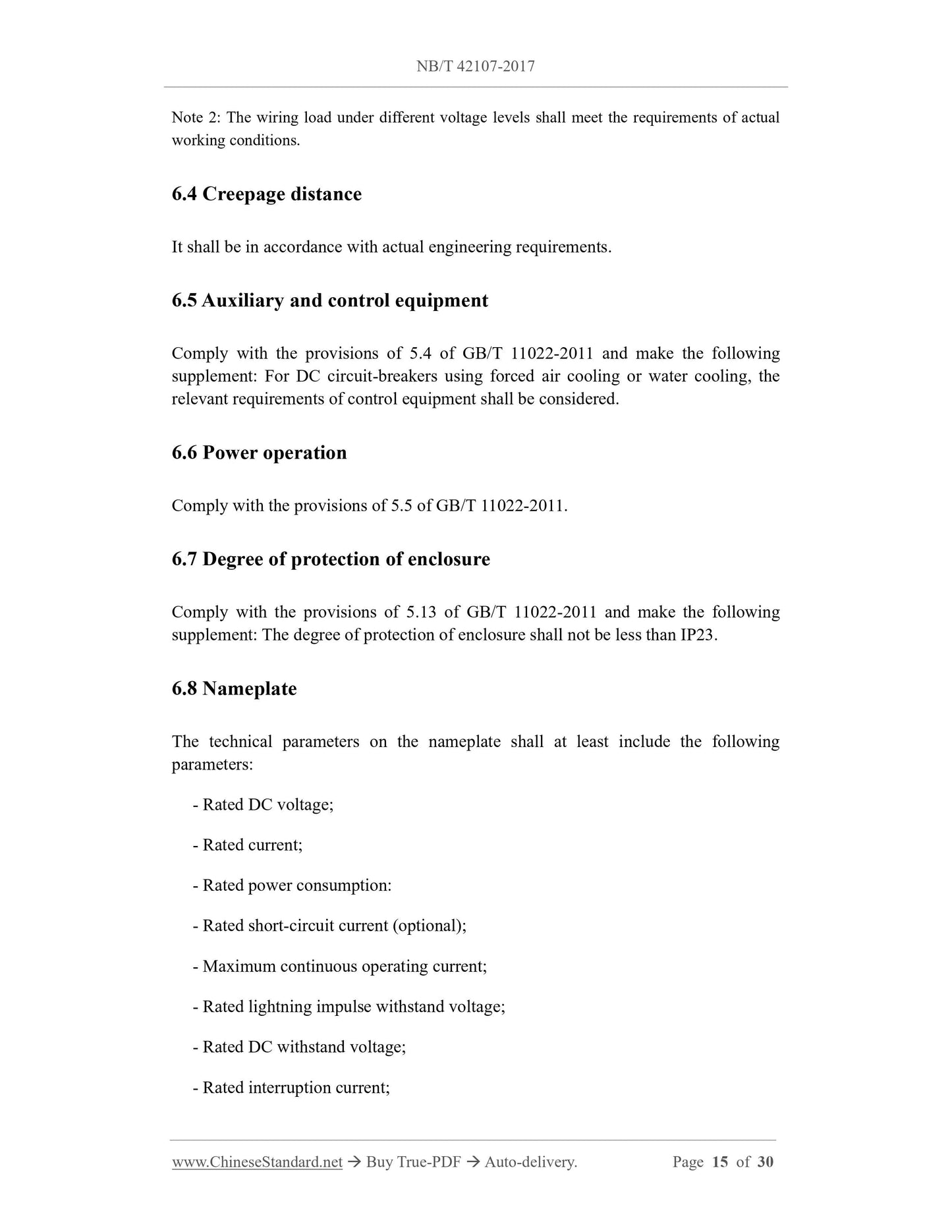
Note 2.The wiring load under different voltage levels shall meet the requirements of actual
working conditions.
6.4 Creepage distance
It shall be in accordance with actual engineering requirements.
6.5 Auxiliary and control equipment
Comply with the provisions of 5.4 of GB/T 11022-2011 and make the following
supplement. For DC circuit-breakers using forced air cooling or water cooling, the
relevant requirements of control equipment shall be considered.
6.6 Power operation
Comply with the provisions of 5.5 of GB/T 11022-2011.
6.7 Degree of protection of enclosure
Comply with the provisions of 5.13 of GB/T 11022-2011 and make the following
supplement. The degree of protect...
View full details