1
/
of
7
www.ChineseStandard.us -- Field Test Asia Pte. Ltd.
NB/T 20019-2010 English PDF (NB/T20019-2010)
NB/T 20019-2010 English PDF (NB/T20019-2010)
Regular price
$220.00
Regular price
Sale price
$220.00
Unit price
/
per
Shipping calculated at checkout.
Couldn't load pickup availability
NB/T 20019-2010: Ageing, screening, and derating rules of electronic elements and devices in safety class instrument and control equipment of nuclear power plants
Delivery: 9 seconds. Download (and Email) true-PDF + Invoice.Get Quotation: Click NB/T 20019-2010 (Self-service in 1-minute)
Newer / historical versions: NB/T 20019-2010
Preview True-PDF
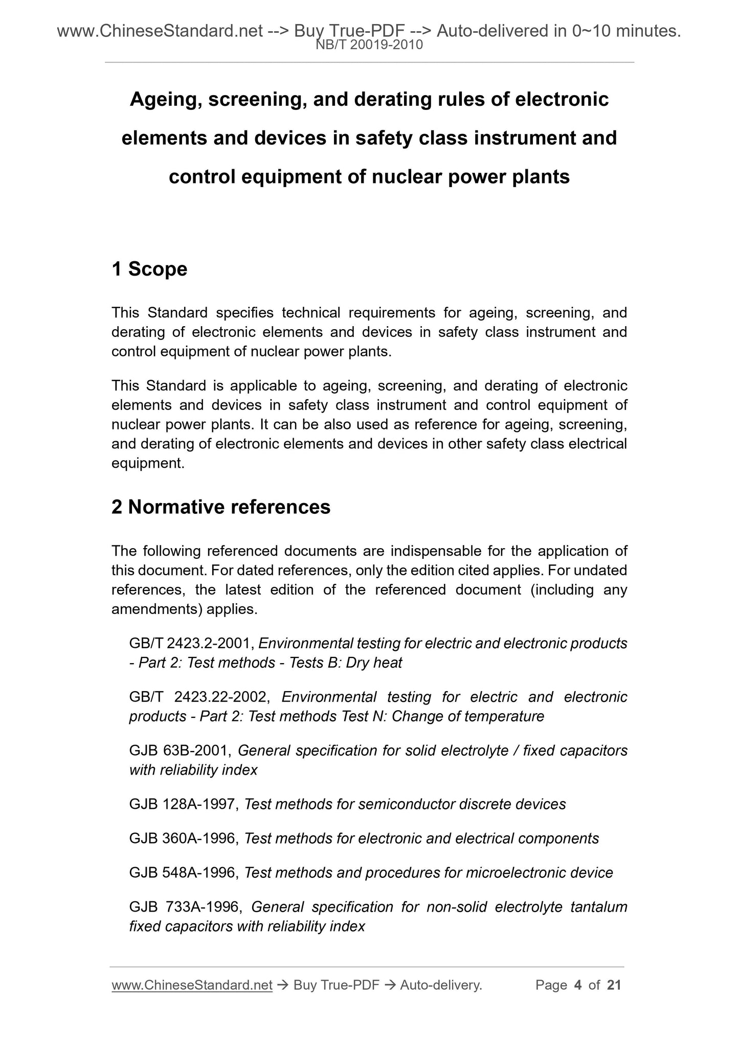
Scope
This Standard specifies technical requirements for ageing, screening, andderating of electronic elements and devices in safety class instrument and
control equipment of nuclear power plants.
This Standard is applicable to ageing, screening, and derating of electronic
elements and devices in safety class instrument and control equipment of
nuclear power plants. It can be also used as reference for ageing, screening,
and derating of electronic elements and devices in other safety class electrical
equipment.
Basic Data
| Standard ID | NB/T 20019-2010 (NB/T20019-2010) |
| Description (Translated English) | Ageing, screening, and derating rules of electronic elements and devices in safety class instrument and control equipment of nuclear power plants |
| Sector / Industry | Energy Industry Standard (Recommended) |
| Classification of Chinese Standard | F81 |
| Classification of International Standard | 27.120.99 |
| Word Count Estimation | 15,159 |
| Date of Issue | 2010-05-01 |
| Date of Implementation | 2010-10-01 |
| Older Standard (superseded by this standard) | EJ/T 504-1990 |
| Quoted Standard | GB/T 2423.2-2001; GB/T 2423.22-2002; GJB 63B-2001; GJB 128A-2001; GJB 360A-1996; GJB 548A-1996; GJB 733A-1996; GJB 972A-2002; GJB/Z 35-1993 |
| Regulation (derived from) | ?National Energy Board Announcement 2010 No.1; Industry Standard Filing Announcement 2010 No.7 (Total No.127) |
| Issuing agency(ies) | National Energy Administration |
| Summary | This standard specifies the technical requirements for nuclear plant safety level mountain instrumentation and control equipment and electronic components aging screened derating use. This standard applies to nuclear power plant safety level electronic components and instrumentation and control equipment derating aging screening, but also for other electronic components for electrical equipment safety level reference or reference aging screening and derating use. |
Share