Skip to product information
1 of 6

PayPal, credit cards. Download editable-PDF and invoice in 1 second!

MT/T 199-1996 English PDF (MTT199-1996)

MT/T 199-1996 English PDF (MTT199-1996)

Regular price $130.00 USD
Regular price Sale price $130.00 USD
Sale Sold out
Shipping calculated at checkout.
Delivery: 3 seconds. Download true-PDF + Invoice.
Get QUOTATION in 1-minute: Click MT/T 199-1996
Historical versions: MT/T 199-1996
Preview True-PDF (Reload/Scroll if blank)

MT/T 199-1996: General specifications for hydraulic drill jumbos for coal mine
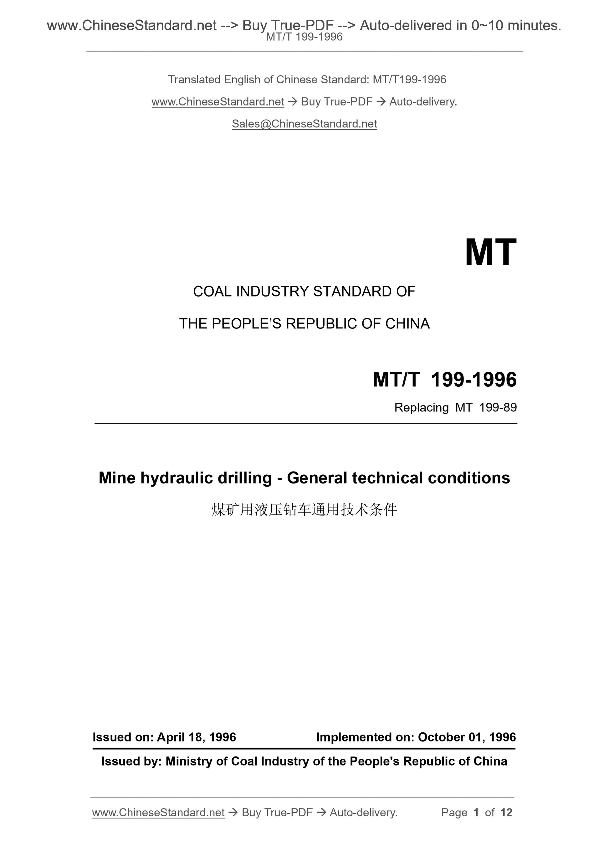
MT/T 199-1996
COAL INDUSTRY STANDARD OF
THE PEOPLE’S REPUBLIC OF CHINA
Replacing MT 199-89
Mine hydraulic drilling - General technical conditions
ISSUED ON: APRIL 18, 1996
IMPLEMENTED ON: OCTOBER 01, 1996
Issued by: Ministry of Coal Industry of the People's Republic of China
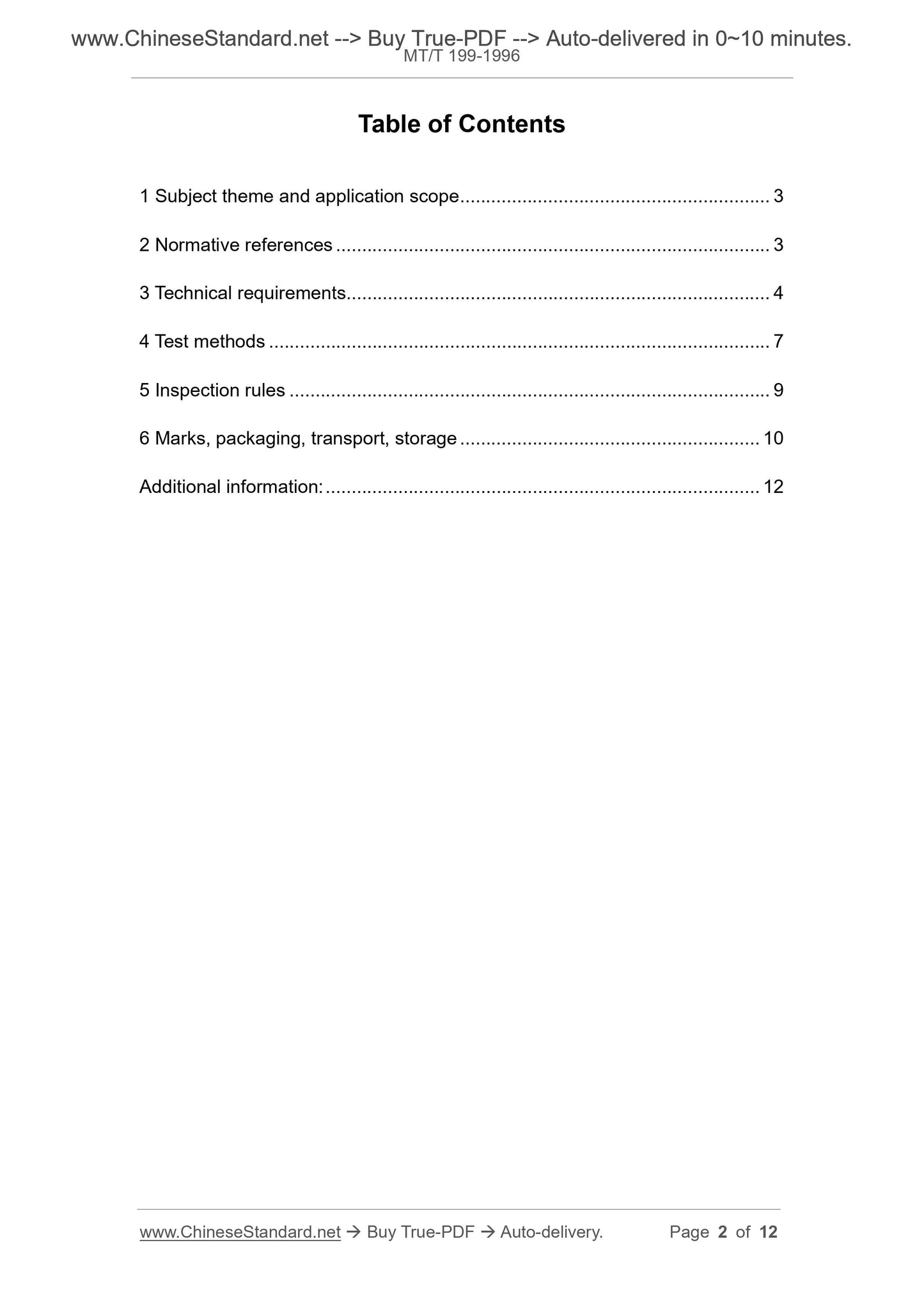
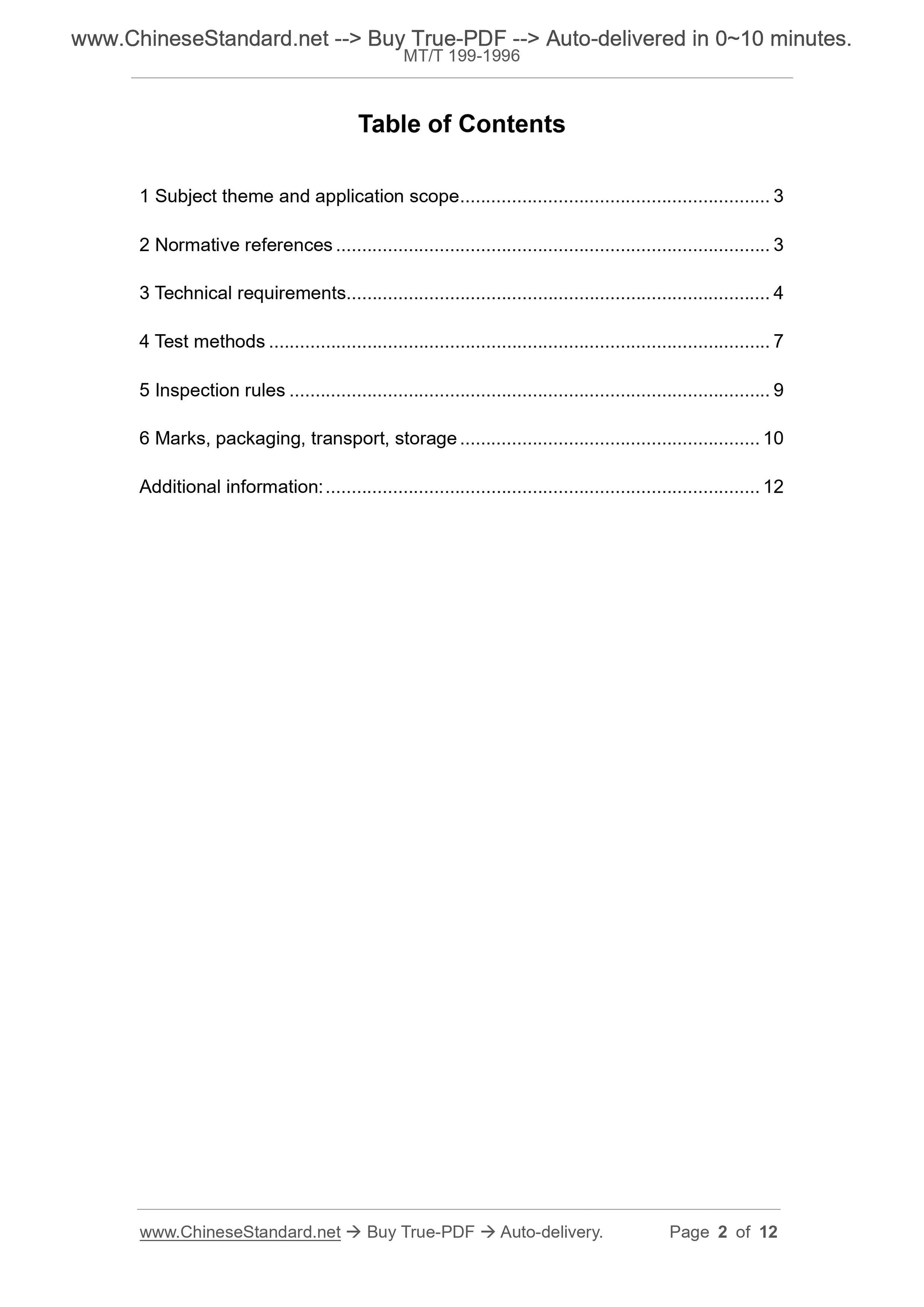
Table of Contents
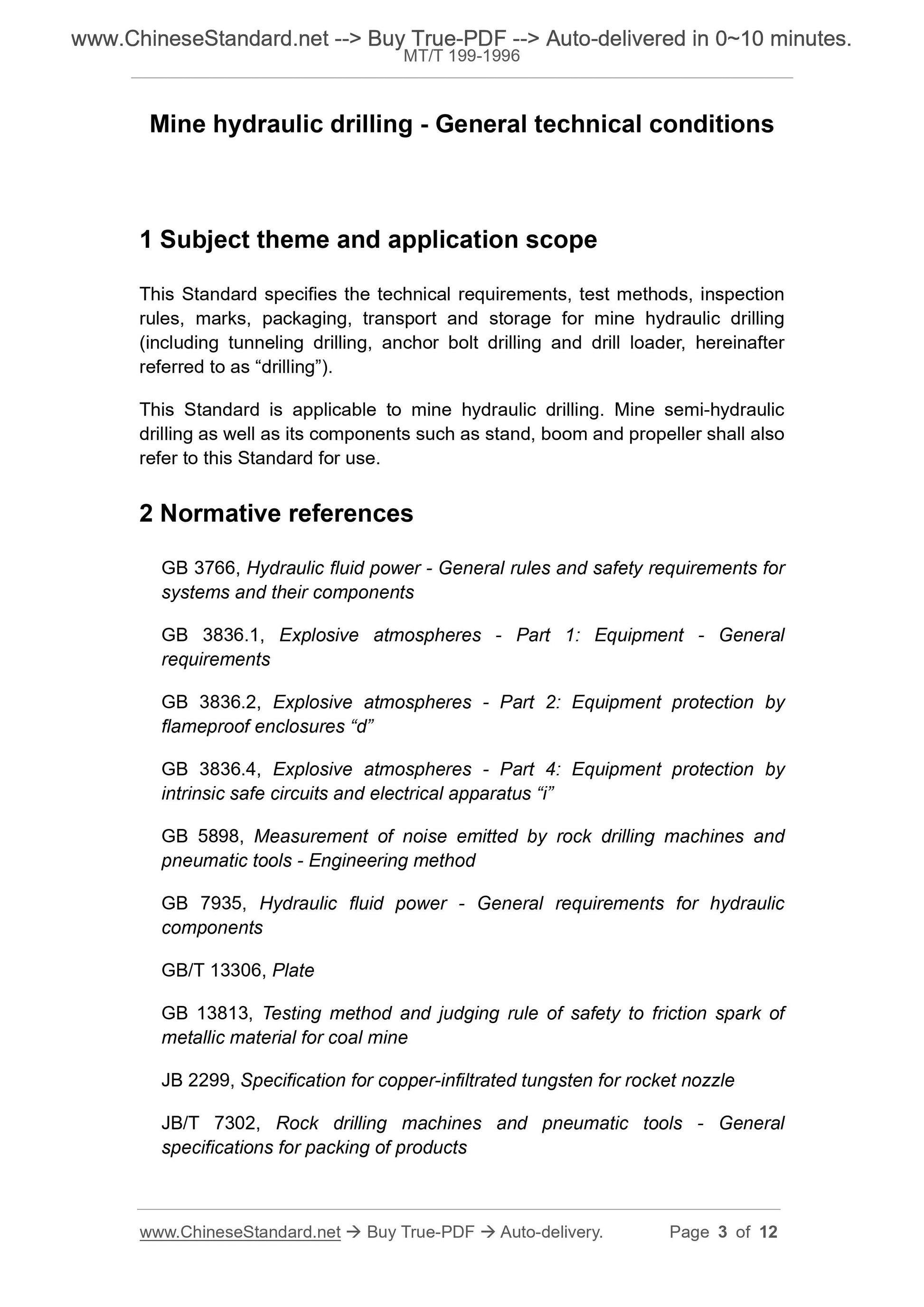
1 Subject theme and application scope ... 3 
2 Normative references ... 3 
3 Technical requirements ... 4 
4 Test methods ... 7 
5 Inspection rules ... 9 
6 Marks, packaging, transport, storage ... 10 
Additional information: ... 12 
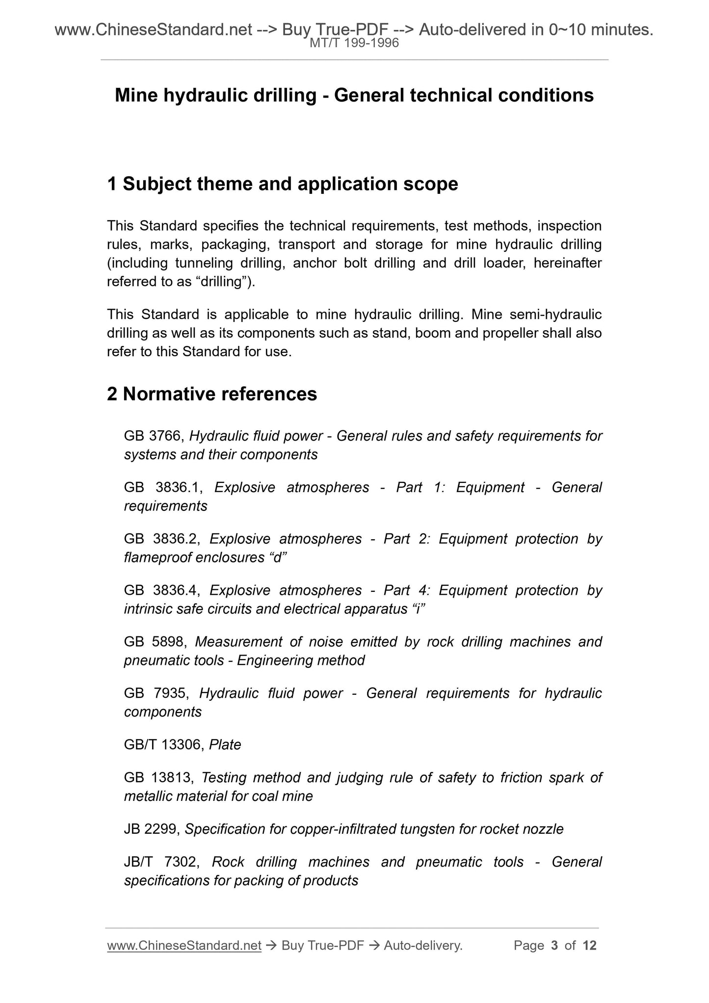
Mine hydraulic drilling - General technical conditions
1 Subject theme and application scope
This Standard specifies the technical requirements, test methods, inspection
rules, marks, packaging, transport and storage for mine hydraulic drilling
(including tunneling drilling, anchor bolt drilling and drill loader, hereinafter
referred to as “drilling”).
This Standard is applicable to mine hydraulic drilling. Mine semi-hydraulic
drilling as well as its components such as stand, boom and propeller shall also
refer to this Standard for use.
2 Normative references
GB 3766, Hydraulic fluid power - General rules and safety requirements for
systems and their components
GB 3836.1, Explosive atmospheres - Part 1: Equipment - General
requirements
GB 3836.2, Explosive atmospheres - Part 2: Equipment protection by
flameproof enclosures “d”
GB 3836.4, Explosive atmospheres - Part 4: Equipment protection by
intrinsic safe circuits and electrical apparatus “i”
GB 5898, Measurement of noise emitted by rock drilling machines and
pneumatic tools - Engineering method
GB 7935, Hydraulic fluid power - General requirements for hydraulic
components
GB/T 13306, Plate
GB 13813, Testing method and judging rule of safety to friction spark of
metallic material for coal mine
JB 2299, Specification for copper-infiltrated tungsten for rocket nozzle
JB/T 7302, Rock drilling machines and pneumatic tools - General
specifications for packing of products
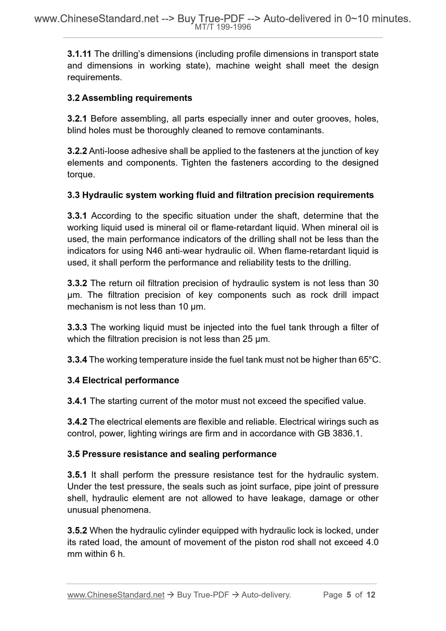
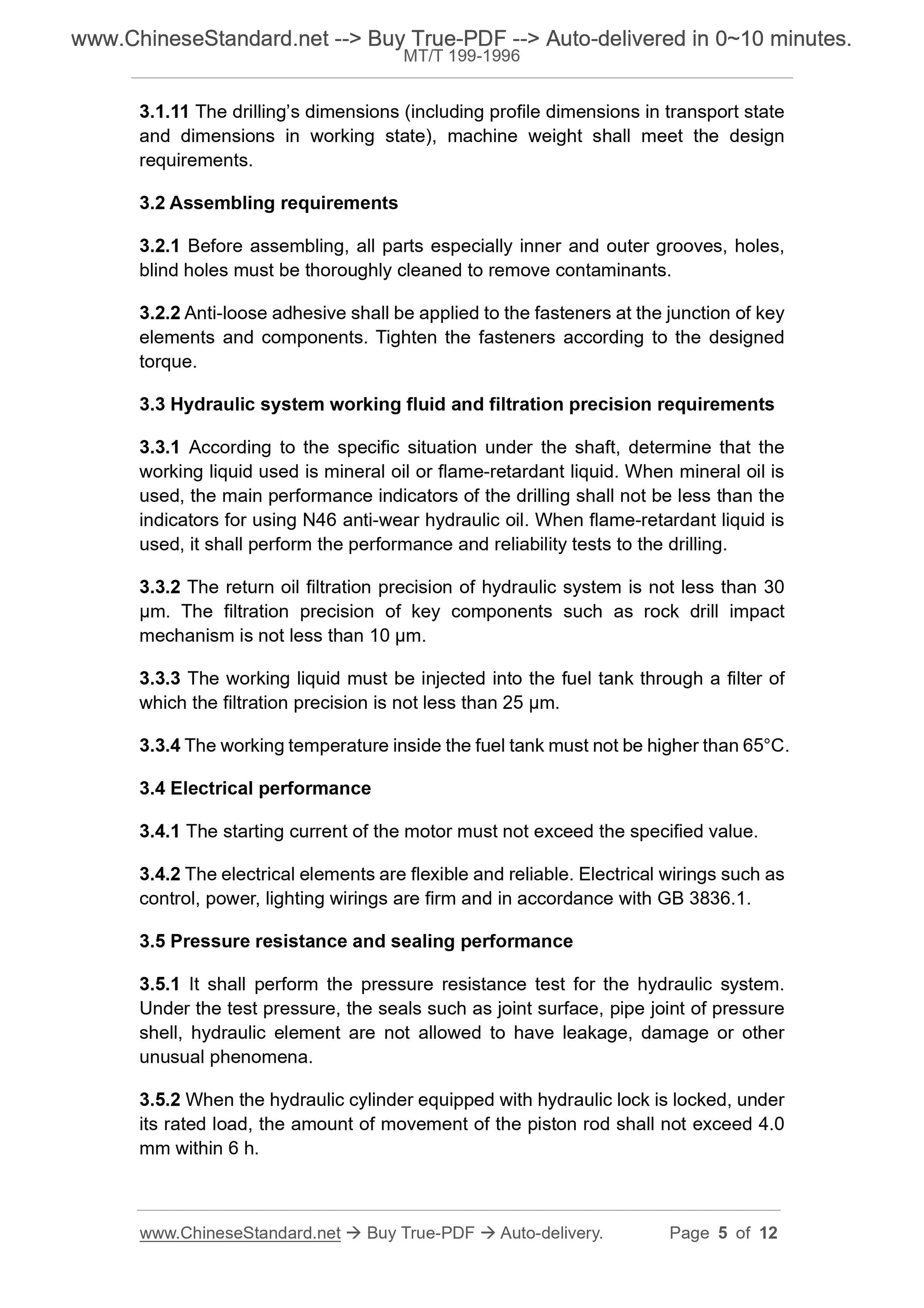
3.1.11 The drilling’s dimensions (including profile dimensions in transport state
and dimensions in working state), machine weight shall meet the design
requirements.
3.2 Assembling requirements
3.2.1 Before assembling, all parts especially inner and outer grooves, holes,
blind holes must be thoroughly cleaned to remove contaminants.
3.2.2 Anti-loose adhesive shall be applied to the fasteners at the junction of key
elements and components. Tighten the fasteners according to the designed
torque.
3.3 Hydraulic system working fluid and filtration precision requirements
3.3.1 According to the specific situation under the shaft, determine that the
working liquid used is mineral oil or flame-retardant liquid. When mineral oil is
used, the main performance indicators of the drilling shall not be less than the
indicators for using N46 anti-wear hydraulic oil. When flame-retardant liquid is
used, it shall perform the performance and reliability tests to the drilling.
3.3.2 The return oil filtration precision of hydraulic system is not less than 30
µm. The filtration precision of key components such as rock drill impact
mechanism is not less than 10 µm.
3.3.3 The working liquid must be injected into the fuel tank through a filter of
which the filtration precision is not less than 25 µm.
3.3.4 The working temperature inside the fuel tank must not be higher than 65°C.
3.4 Electrical performance
3.4.1 The starting current of the motor must not exceed the specified value.
3.4.2 The electrical elements are flexible and reliable. Electrical wirings such as
control, power, lighting wirings are firm and in accordance with GB 3836.1.
3.5 Pressure resistance and sealing performance
3.5.1 It shall perform the pressure resistance test for the hydraulic system.
Under the test pressure, the seals such as joint surface, pipe joint of pressure
shell, hydraulic element are not allowed to have leakage, damage or other
unusual phenomena.
3.5.2 When the hydraulic cylinder equipped with hydraulic lock is locked, under
its rated load, the amount of movement of the piston rod shall not exceed 4.0
mm within 6 h.
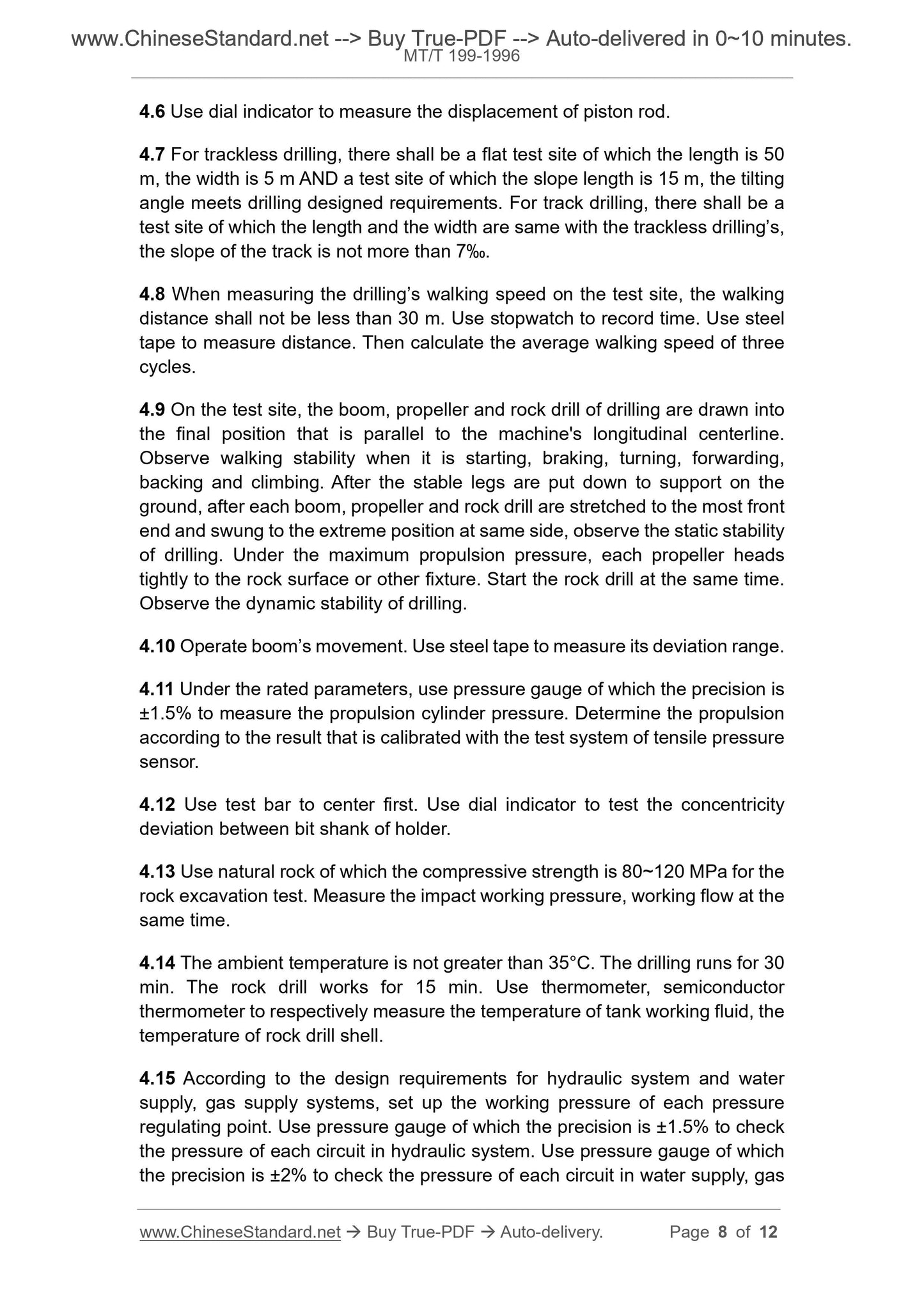
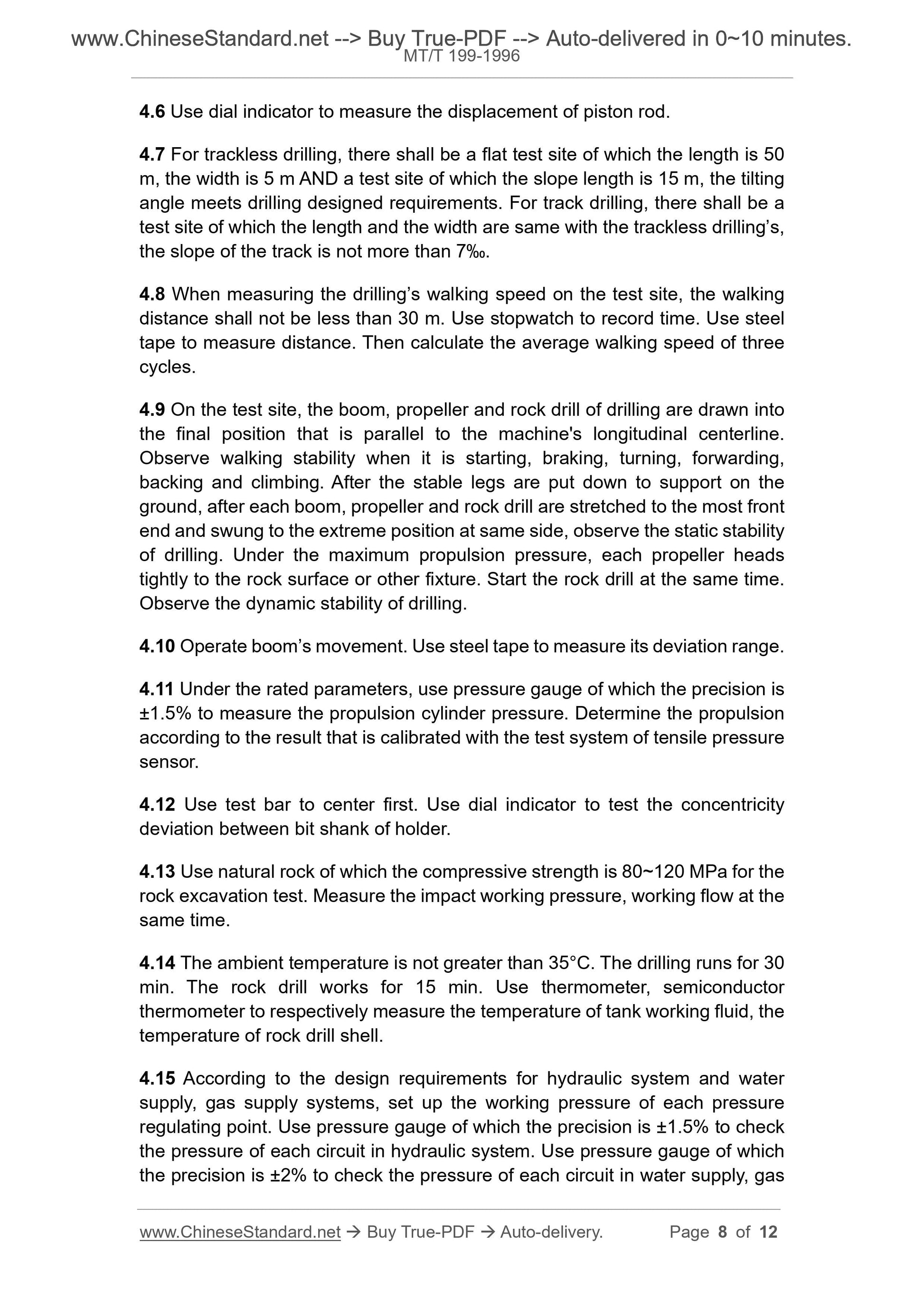
4.6 Use dial indicator to measure the displacement of piston rod.
4.7 For trackless drilling, there shall be a flat test site of which the length is 50
m, the width is 5 m AND a test site of which the slope length is 15 m, the tilting
angle meets drilling designed requirements. For track drilling, there shall be a
test site of which the length and the width are same with the trackless drilling’s,
the slope of the track is not more than 7‰.
4.8 When measuring the drilling’s walking speed on the test site, the walking
distance shall not be less than 30 m. Use stopwatch to record time. Use steel
tape to measure distance. Then calculate the average walking speed of three
cycles.
4.9 On the test site, the boom, propeller and rock drill of drilling are drawn into
the final position that is parallel to the machine's longitudinal centerline.
Observe walking stability when it is starting, braking, turning, forwarding,
backing and climbing. After the stable legs are put down to support on the
ground, after each boom, propeller and rock drill are stretched to the most front
end and swung to the extreme position at same side, observe the static stability
of drilling. Under the maximum propulsion pressure, each propeller heads
tightly to the rock surface or other fixture. Start the rock drill at the same time.
Observe the dynamic stability of drilling.
4.10 Operate boom’s movement. Use steel tape to measure its deviation range.
4.11 Under the rated parameters, use pressure gauge of which the precision is
±1.5% to measure the propulsion cylinder pressure. Determine the propulsion
according to the result that is calibrated with the test system of tensile pressure
sensor.
4.12 Use test bar to center first. Use dial indicator to test the concentricity
deviation between bit shank of holder.
4.13 Use natural rock of which the compressive strength is 80~120 MPa for the
rock excavation test. Measure the impact working pressure, working flow at the
same time.
4.14 The ambient temperature is not greater than 35°C. The drilling runs for 30
min. The rock drill works for 15 min. Use thermometer, semiconductor
thermometer to respectively measure the temperature of tank working fluid, the
temperature of rock drill shell.
4.15 According to the design requirements for hydraulic system and water
supply, gas supply systems, set up the working pressure of each pressure
regulating point. Use pressure gauge of which the precision is ±1.5% to check
the pressure of each circuit in hydraulic system. Use pressure gauge of which
the precision is ±2% to check the pressure of each circuit in water supply, gas
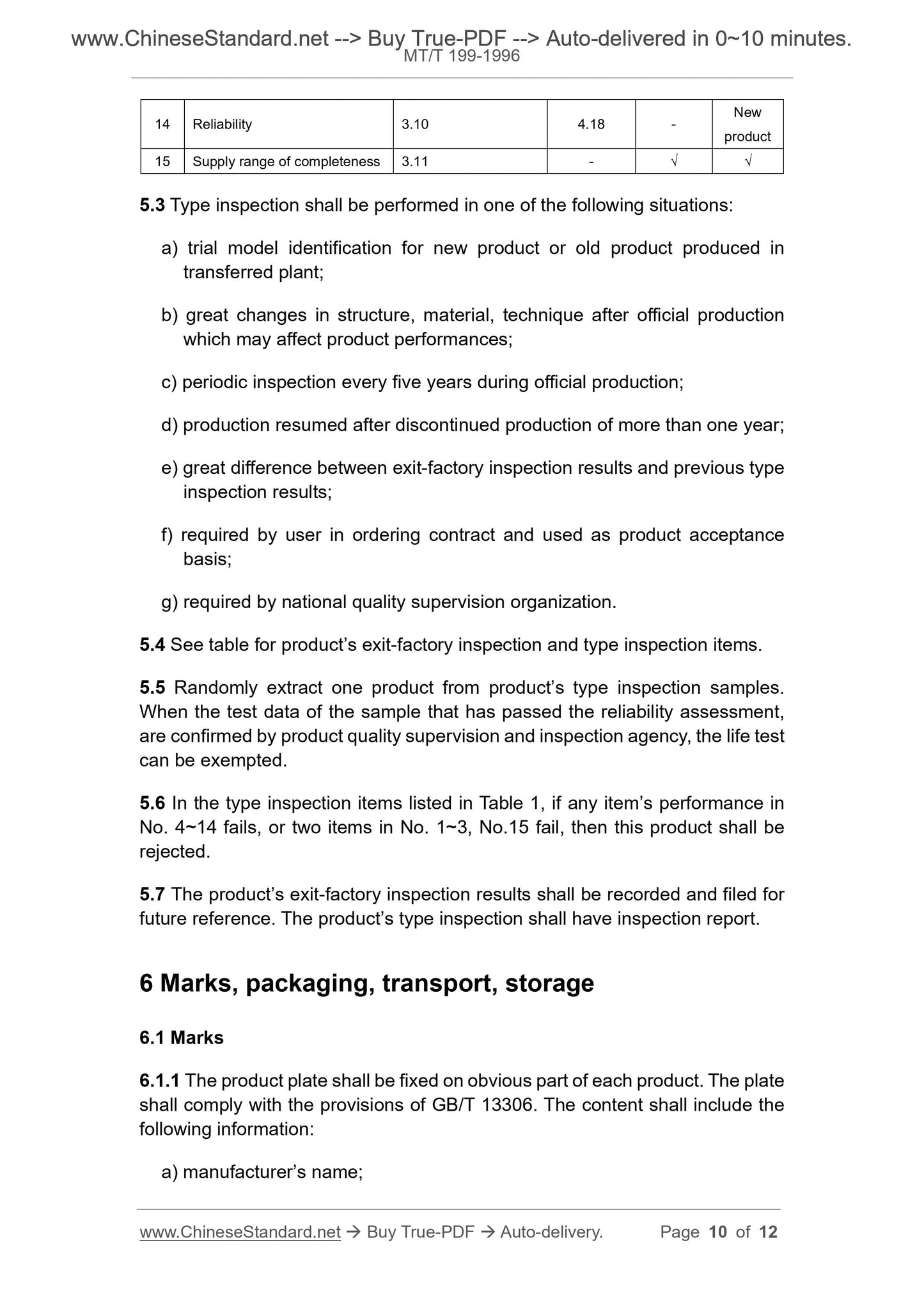
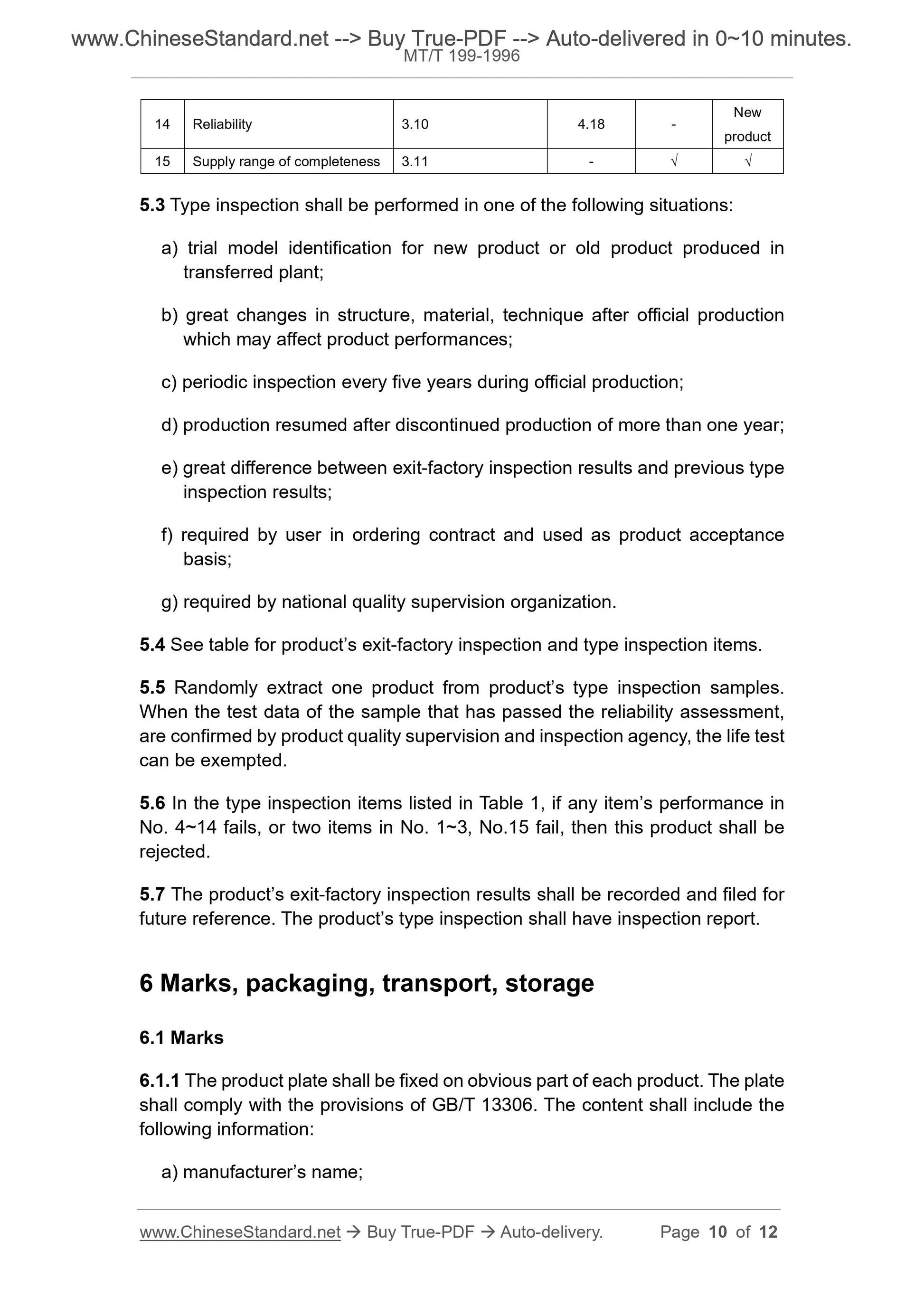
14 Reliability 3.10 4.18 - New product
15 Supply range of completeness 3.11 - √ √
5.3 Type inspection shall be performed in one of the following situations:
a) trial model identification for new product or old product produced in
transferred plant;
b) great changes in structure, material, technique after official production
which may affect product performances;
c) periodic inspection every five years during official production;
d) production resumed after discontinued production of more than one year;
e) great difference between exit-factory inspection results and previous type
inspection results;
f) required by user in ordering contract and used as product ac...
View full details