Skip to product information
1 of 3

PayPal, credit cards. Download editable-PDF and invoice in 1 second!

JJG 527-2015 English PDF

JJG 527-2015 English PDF

Regular price $150.00 USD
Regular price Sale price $150.00 USD
Sale Sold out
Shipping calculated at checkout.
Delivery: 3 seconds. Download true-PDF + Invoice.
Get Quotation: Click JJG 527-2015 (Self-service in 1-minute)
Historical versions (Master-website): JJG 527-2015
Preview True-PDF (Reload/Scroll-down if blank)

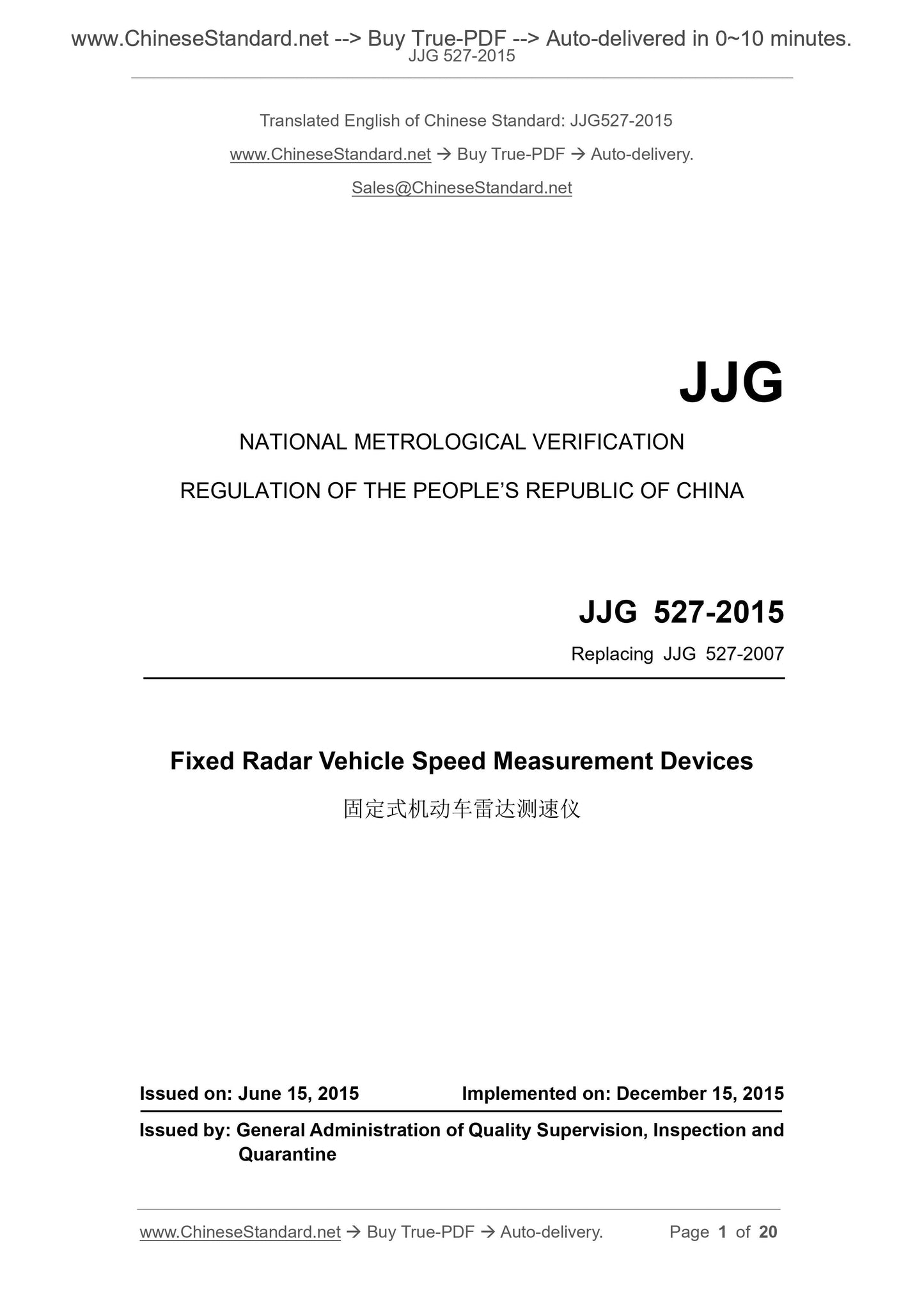
JJG 527-2015: Fixed Radar Vehicle Speed Measurement Devices
JJG 527-2015
Fixed Radar Vehicle Speed Measurement Devices
National Metrology Verification Regulations of the People's Republic
Fixed motor vehicle radar speedometer
Released on.2015-06-15
2015-12-15 implementation
The General Administration of Quality Supervision, Inspection and Quarantine issued
Fixed motor vehicle radar speedometer
Verification procedure
Replace JJG 527-2007
Focal Point. National Vibration Shock Velocity Measurement Technical Committee
Main drafting unit. Beijing Institute of Metrology and Measurement Science
China Institute of Metrology
Zhejiang Institute of Metrology
Participated in drafting unit. China Testing Technology Research Institute
Guangdong Institute of Metrology
Anhui Landun Optical Electronics Co., Ltd.
Beijing Zhonglian Tongda Technology Development Co., Ltd.
This regulation entrusts the National Vibration Shock Velocity Measurement Technical Committee to explain
The main drafters of this procedure.
Dai Jinzhou (Beijing Institute of Metrology and Measurement Science)
Du Lei (China Institute of Metrology)
Lin Feng (Zhejiang Institute of Metrology)
Participate in the drafters.
Yang Chunsheng (China Testing Technology Research Institute)
Huang Zhenyu (Guangdong Institute of Metrology)
Qian Jiang (Anhui Landun Optical Electronics Co., Ltd.)
Lu Dong (Beijing Zhonglian Tongda Technology Development Co., Ltd.)
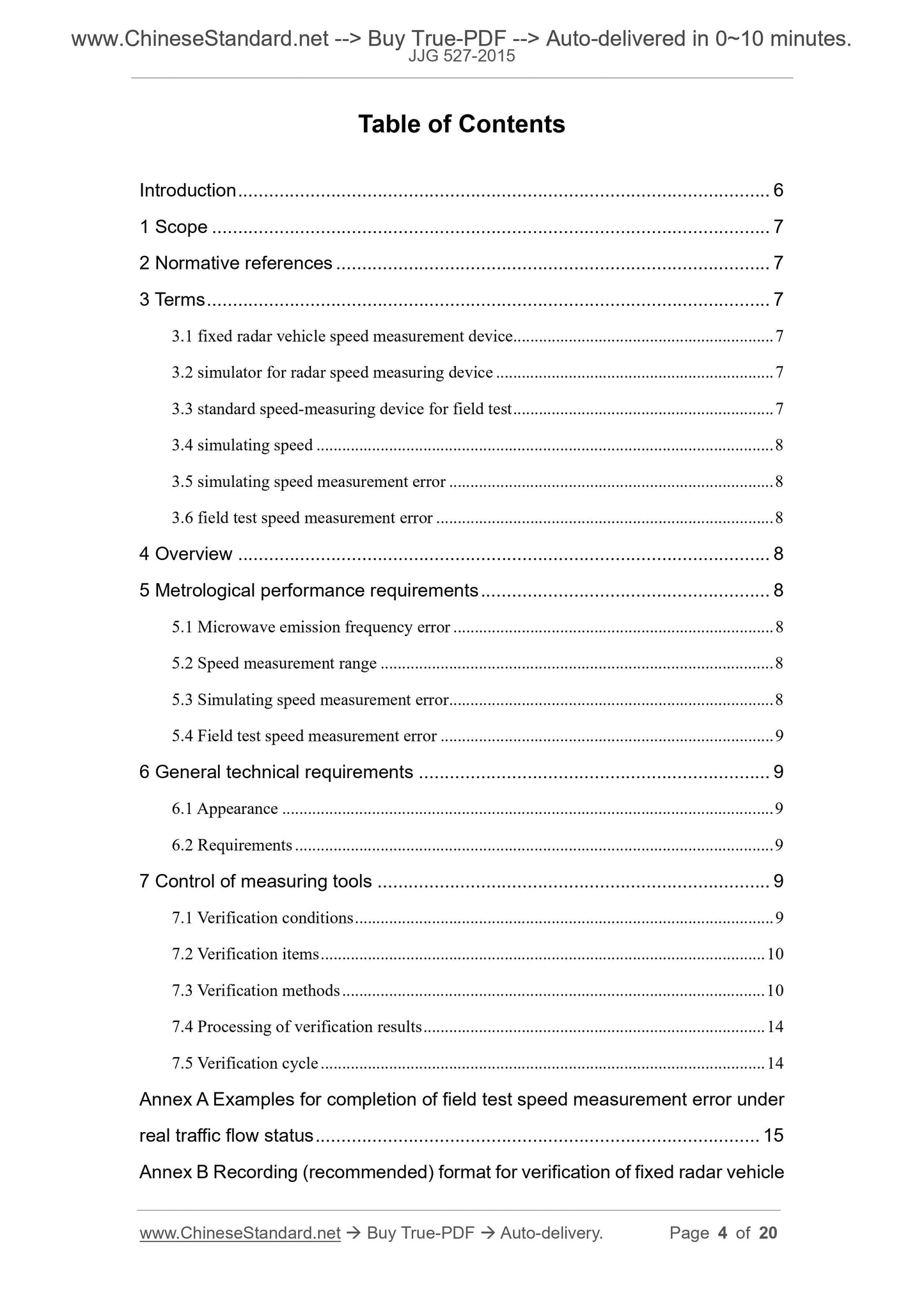
table of Contents
Introduction (II)
1 range (1)
2 References (1)
3 terms (1)
3.1 Fixed motor vehicle radar speedometer (1)
3.2 Radar Speedometer Simulation Verification Device (1)
3.3 On-site speed measurement standard device (1)
3.4 Analog standard speed value (1)
3.5 Analog Velocity Error (1)
3.6 On-site speed measurement error (1)
4 Overview (1)
5 Metrological performance requirements (2)
5.1 Microwave transmission frequency error (2)
5.2 Speed range (2)
5.3 Analog Velocity Error (2)
5.4 On-site speed measurement error (2)
6 General technical requirements (2)
6.1 Appearance (2)
6.2 Requirements (2)
7 measuring instrument control (2)
7.1 Verification conditions (2)
7.2 Verification project (3)
7.3 Verification method (3)
7.4 Processing of verification results (5)
7.5 Verification cycle (5)
Annex A Example of completion of on-site speed measurement error verification under real traffic flow conditions (6)
Annex B Fixed Vehicle Radar Speedometer Calibration Record (Recommended) Format (7)
Annex C Fixed Motor Vehicle Radar Speedometer Verification Certificate/Verification Result Notice Page Format (8)
introduction
JJF1002 "National Metrology Verification Procedures Writing Rules", JJF1001 "General Measurement Terms and Definitions",
JJF1059.1 "Measurement and Representation of Measurement Uncertainty" together constitutes a basic series of rules supporting the revision of this regulation.
Fan. Main reference JJF1335-2012 "Typed Radar Speedometer Type Evaluation Outline", JJG 1074-2012
Technical specifications such as "Motor Vehicle Laser Speedometer".
This procedure is to amend JJG 527-2007. Compared with JJG 527-2007, except for editorial revisions
The main technical changes are as follows.
--- It is clear that the procedures apply to fixed-mounted motor vehicle radar speedometers (see 1);
--- Cancel the verification of the speed range and the verification of the analog speed measurement in the subsequent verification;
--- Increased the on-site speed error detection with the normal driving vehicle as the measured object under the real traffic flow state
The method of setting (see 7.3.4);
--- Add an example of the on-site speed measurement error verification in Appendix A for real traffic flow conditions.
The previous versions of this procedure were released as follows.
---JJG 527-2007 "Automobile Overspeed Automatic Monitoring System"
---JJG 527-1988 "fixed angle radar speedometer".
Fixed motor vehicle radar speedometer verification procedure
1 Scope
This procedure is applicable to fixed-mounted vehicles that measure the speed of motor vehicles using the principle of Doppler effect.
The first verification, subsequent verification and in-use inspection of the radar speedometer.
2 reference files
JJG 1074-2012 Motor Vehicle Laser Speedometer
JJF1335-2012 Fixed-angle radar speedometer type evaluation outline
GB/T 21255-2007 Motor vehicle speedometer
For dated references, only dated versions apply to this Code; any undated quotation
The latest version (including all amendments) applies to this procedure.
3 terms
3.1 fixed motor vehicle radar speedometer fixedradarvehiclespeedmeasurementdevice
It refers to a radar speedometer that is fixedly mounted at the measurement position and used to measure the speed of the motor vehicle.
3.2 radar speedometer simulation verification device simulatorforradarspeedmeasuringdevice
For receiving a continuous microwave signal transmitted by the radar speedometer, and transmitting a Dopp corresponding to the set simulation speed value
Dedicated detection equipment for microwave signals.
3.3 on-site speed standard device standardspeed-measuringdeviceforfieldtest
A special detection device for measuring the speed of a motor vehicle passing through a stationary motor vehicle radar speedometer.
3.4 Analog standard speed value timingspeed
The radar speedometer simulates the speed value provided by the verification device.
3.5 analog speed error simulationspeedmeasurementerror
The absolute error of the speed measurement of the fixed motor vehicle radar speedometer and the simulated standard speed value.
3.6 Field speed error fieldtestspeedmeasurementerror
Fixed motor vehicle radar speedometer and on-site speed standard device (or standard) at the same time and at the same location
Speedometer) The speed measurement error of the same vehicle under test.
4 Overview
Fixed motor vehicle radar speedometer refers to the appropriate position to be installed on the road based on the Doppler effect principle.
A device that detects real-time, automatic measurement of the speed of a motor vehicle in a lane.
Fixed radar speedometers are usually composed of radar antennas, signal processing units, image processing units, communication units, and auxiliary
It is composed of a lighting unit and a speed display unit.
5 Metrological performance requirements
5.1 Microwave transmission frequency error
X-band. (f0 ± 25) MHz;
K-band. (f0 ± 45) MHz;
Ka band. (f0 ± 100) MHz.
Where f0 is the nominal value of the microwave transmitting frequency of the fixed motor vehicle radar speedometer, MHz.
5.2 Speed range
At least (20~180)km/h is satisfied.
5.3 Simulated speed measurement error
(-4~0)km/h.
5.4 On-site speed measurement error
< 100km/h, (-6~0)km/h;
When ≥100km/h, (-6~0)%.
6 General technical requirements
6.1 Appearance
6.1.1 Fixed motor vehicle radar speedometer shall have a nameplate indicating the product name, specification, model number, radar
The nominal frequency of the launch frequency, the manufacturer and the date, and shall be marked with the manufacturing license mark and number of the measuring instrument.
6.1.2 The appearance of the fixed motor vehicle radar speedometer should not affect the mechanical damage of normal use, and the fasteners are not
Should be loose and structurally complete.
6.2 Requirements
6.2.1 The setting or adjustment button of the fixed motor vehicle radar speedometer should be able to be used normally, and the operation buttons should be light and flexible.
Live and operate normally.
6.2.2 The connection line and connector of the fixed motor vehicle radar speedometer should be complete and reliable.
6.2.3 Fixed motor vehicle radar speedometer should have independent speed display unit. After normal operation, the display of the display screen should be
Complete, clear and eye-catching.
7 measuring instrument control
Measurement appliance control includes. first verification, subsequent verification, and in-use inspection.
7.1 Verification conditions
7.1.1 Characterizing environmental conditions
7.1.1.1 Laboratory verification environment.
1) Temperature. (15~25) °C.
2) Relative humidity. < 85%.
7.1.1.2 On-site verification environment.
1) Temperature. (-25~55) °C.
2) Relative humidity. < 85%.
7.1.2 Standard equipment for verification
The standard equipment and technical requirements for verification are shown in Table 1.
Table 1 Standard equipment for verification
Serial number verification project
Main verification equipment
Name technical requirements
Microwave
Shooting frequency
error
Microwave digital frequency meter
Frequency range. (8~40) GHz
Frequency accuracy. ±2×10⁻⁴
Frequency stability. 2×10⁻⁵/s
Receive horn antenna 3cm, 1.25cm, 8mm
2 speed range
3 analog speed measurement error
Radar speedometer simulation verification device
Speed range. at least (20~200)km/h
MPE. ±0.3km/h
4 on-site speed measurement error
Field speed standard device
Standard speedometer
Speed range. (20~180)km/h
MPE. ±1%
(with adjustable speed trigger position and
The tested device detects the same area.)
7.2 Verification project
The items for the first verification, subsequent verification and in-use inspection are shown in Table 2.
Table 2 List of verification items
Serial number item first verification follow-up verification in-use inspection
1 General technical requirements
2 microwave emission frequency error - -
3 speed range - -
4 analog speed error - -
5 on-site speed measurement error -
Note. “ ” is the item to be inspected and “-” is the item that can be unchecked.
7.3 Verification method
Select the verification item according to the requirements of 7.2. The verification sequence is firstly applied to the general method according to the methods of 7.3.1, 7.3.2, and 7.3.3.
Technical requirements, microwave transmission frequency error, speed measurement range and analog speed measurement error are verified and valid data is recorded,
After the method of 7.3.4 is used to verify the on-site speed measurement error, the subsequent verification may not check the microwave transmission frequency error and speed measurement.
Range, analog speed measurement error items.
7.3.1 General technical requirements check
The fixed-type motor vehicle radar speedometer should be able to work normally after being turned on, and check by hand and visual inspection.
Should meet the requirements of 6.1, 6.2.
7.3.2 Verification of microwave transmission frequency error
The schematic diagram of the microwave transmission frequency error verification of the fixed motor vehicle radar speedometer is shown in Figure 1, and the receiving antenna is made.
It is on the same axis as the microwave transmitting antenna of the fixed motor vehicle radar speedometer, and the output port of the receiving antenna is connected to
Microwave digital frequency meter.
Figure 1 Block diagram of the microwave transmission frequency error verification system
Turn on the power supply of the microwave digital frequency meter and the fixed motor vehicle radar speedometer, according to the requirements of the instrument manual.
heat. The stationary motor vehicle radar speedometer continuously emits microwaves, and the measured values are read on the microwave digital frequency meter. Wei Wei
The wave transmission frequency is measured 3 times, and the error of the microwave transmission frequency is calculated according to formula (1).
Δfx=f0-fx (1)
In the formula.
Δfx --- fixed motor vehicle radar speedometer microwave transmission frequency error, MHz;
Fx --- fixed motor vehicle radar speed measuring instrument microwave transmission frequency measurement value, MHz;
F0 --- The nominal value of the microwave transmission frequency of the fixed motor vehicle radar speedometer, MHz.
The maximum measurement error of the microwave emission frequency in the three measurements is the final measurement result, which should meet the requirements of 5.1.
7.3.3 Verification of speed range and analog speed measurement error
A schematic diagram of the speed measurement range and the analog speed measurement error of the fixed motor vehicle radar speedometer is shown in Fig. 2.
Figure 2 Block diagram of the speed range and analog speed error verification system
According to the different bands, trigger mode, installation angle, test software and other characteristics of the fixed motor vehicle radar speedometer
Set the radar speedometer simulation verification device.
Before the verification of the speed range and the analog speed measurement error, the microwave transmitting end of the fixed motor vehicle radar speedometer and the lightning should be
The receiving end of the speed measuring instrument simulation verification device is on the same axis to ensure the normal operation of the verification work.
The radar speedometer simulation verification device sets a 7-point standard speed value in the range of (20~180)km/h (where
20km/h, 60km/h, 120km/h, 180km/h points must be verified). 3 measurements per point, each simulation
The speed measurement error should meet the requirements of 5.3, and the speed measurement range should meet the requirements of 5.2.
7.3.4 Verification of on-site speed measurement error
Install according to the requirements of the on-site speed measurement standard device (or standard speedometer), adjust it to be in normal working condition
state. The verification personnel can select the following one according to the actual situation of the road in the installation section of the fixed motor vehicle radar speedometer.
Method for on-site speed measurement error verification.
(1) In the state of real traffic flow, the vehicle that is driving normally is the object to be tested, and the on-site speed measurement standard device and solid
The fixed-type motor vehicle radar speedometer simultaneously measures the same measured object in the detection area, and records 30 sets of effective measurements.
The value, each speed error should meet the requirements of 5.4, see Appendix A for specific operations.
(2) The test vehicle equipped with the st...
View full details