JJG 145-2007 English PDF (JJG145-2007)
Regular price
$370.00 USD
Regular price
Sale price
$370.00 USD
Unit price
/
per
Delivery: 3 seconds. Download true-PDF + Invoice.
Get QUOTATION in 1-minute: Click JJG 145-2007
Historical versions: JJG 145-2007
Preview True-PDF (Reload/Scroll if blank)
JJG 145-2007: Verification Regulation of Pendulum Impact Testing Machines
JJG 145-2007
NATIONAL METROLOGICAL VERIFICATION STANDARD
OF THE PEOPLE’S REPUBLIC OF CHINA
Replacing JJG 145-1982
Pendulum Impact Testing Machines
ISSUED ON: AUGUST 21, 2007
IMPLEMENTED ON: FEBRUARY 21, 2008
Issued by: General Administration of Quality Supervision, Inspection and
Quarantine of the People's Republic of China
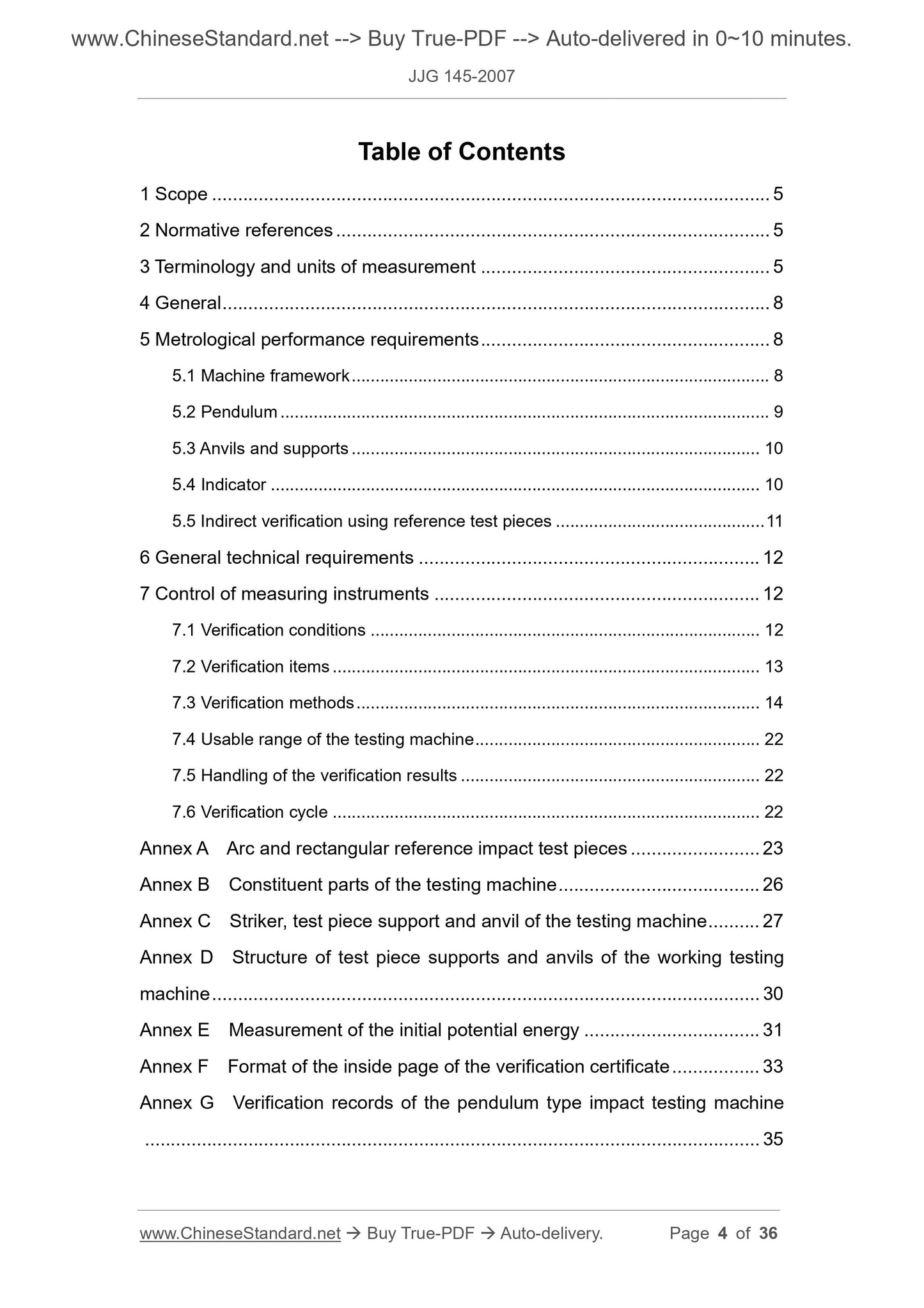
Table of Contents
1 Scope ... 5
2 Normative references ... 5
3 Terminology and units of measurement ... 5
4 General ... 8
5 Metrological performance requirements ... 8
5.1 Machine framework ... 8
5.2 Pendulum ... 9
5.3 Anvils and supports ... 10
5.4 Indicator ... 10
5.5 Indirect verification using reference test pieces ... 11
6 General technical requirements ... 12
7 Control of measuring instruments ... 12
7.1 Verification conditions ... 12
7.2 Verification items ... 13
7.3 Verification methods ... 14
7.4 Usable range of the testing machine ... 22
7.5 Handling of the verification results ... 22
7.6 Verification cycle ... 22
Annex A Arc and rectangular reference impact test pieces ... 23
Annex B Constituent parts of the testing machine ... 26
Annex C Striker, test piece support and anvil of the testing machine ... 27
Annex D Structure of test piece supports and anvils of the working testing
machine ... 30
Annex E Measurement of the initial potential energy ... 31
Annex F Format of the inside page of the verification certificate ... 33
Annex G Verification records of the pendulum type impact testing machine
... 35
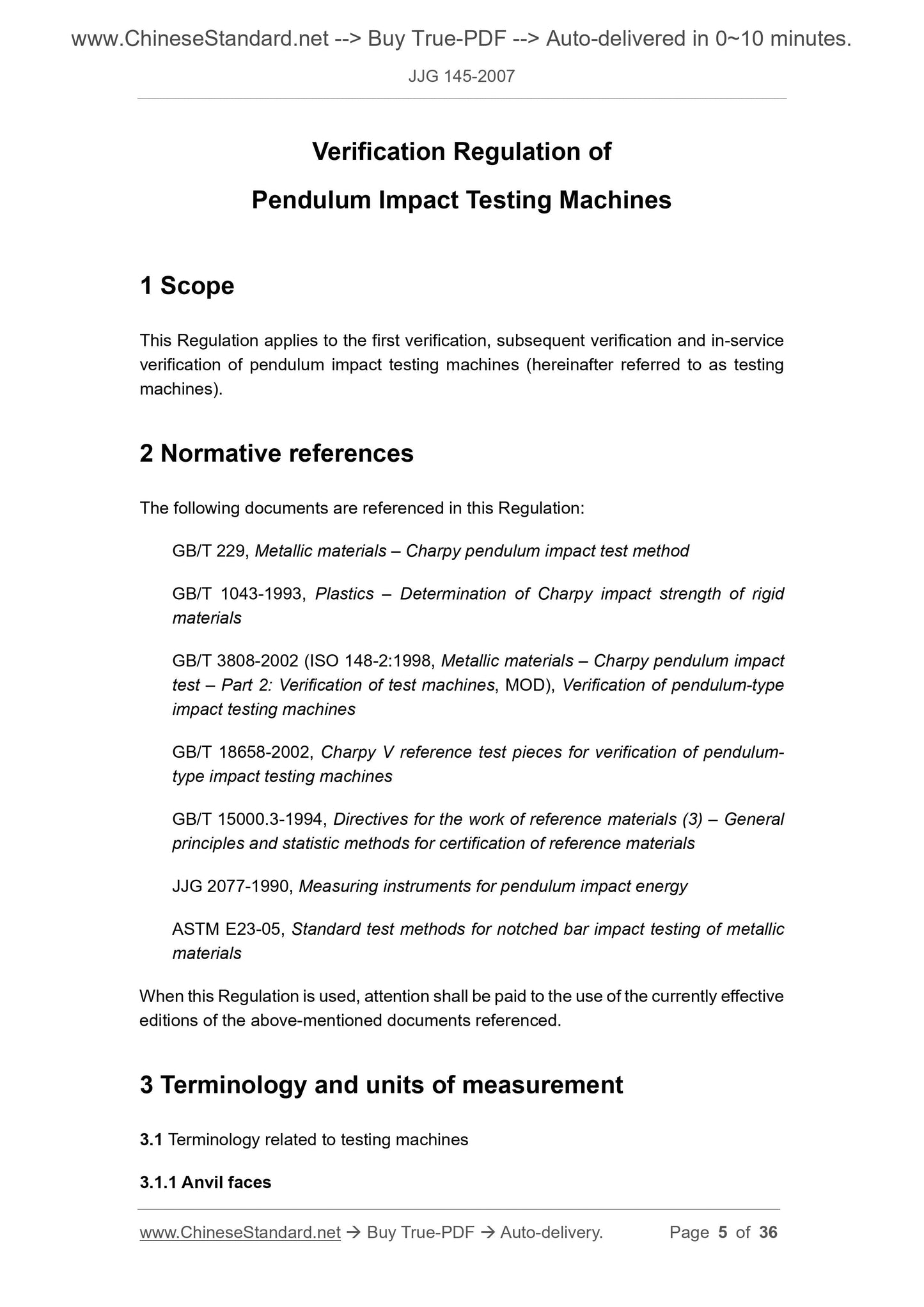
Verification Regulation of
Pendulum Impact Testing Machines
1 Scope
This Regulation applies to the first verification, subsequent verification and in-service
verification of pendulum impact testing machines (hereinafter referred to as testing
machines).
2 Normative references
The following documents are referenced in this Regulation:
GB/T 229, Metallic materials – Charpy pendulum impact test method
GB/T 1043-1993, Plastics – Determination of Charpy impact strength of rigid
materials
GB/T 3808-2002 (ISO 148-2:1998, Metallic materials – Charpy pendulum impact
test – Part 2: Verification of test machines, MOD), Verification of pendulum-type
impact testing machines
GB/T 18658-2002, Charpy V reference test pieces for verification of pendulum-
type impact testing machines
GB/T 15000.3-1994, Directives for the work of reference materials (3) – General
principles and statistic methods for certification of reference materials
JJG 2077-1990, Measuring instruments for pendulum impact energy
ASTM E23-05, Standard test methods for notched bar impact testing of metallic
materials
When this Regulation is used, attention shall be paid to the use of the currently effective
editions of the above-mentioned documents referenced.
3 Terminology and units of measurement
3.1 Terminology related to testing machines
3.1.1 Anvil faces
18658.
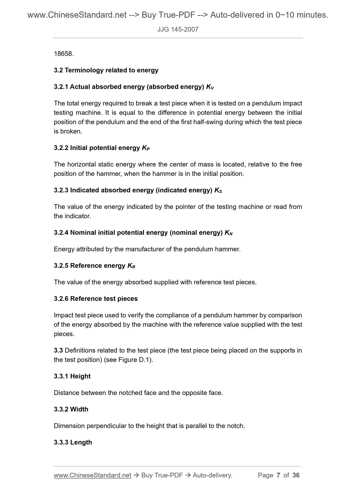
3.2 Terminology related to energy
3.2.1 Actual absorbed energy (absorbed energy) KV
The total energy required to break a test piece when it is tested on a pendulum impact
testing machine. It is equal to the difference in potential energy between the initial
position of the pendulum and the end of the first half-swing during which the test piece
is broken.
3.2.2 Initial potential energy KP
The horizontal static energy where the center of mass is located, relative to the free
position of the hammer, when the hammer is in the initial position.
3.2.3 Indicated absorbed energy (indicated energy) KS
The value of the energy indicated by the pointer of the testing machine or read from
the indicator.
3.2.4 Nominal initial potential energy (nominal energy) KN
Energy attributed by the manufacturer of the pendulum hammer.
3.2.5 Reference energy KR
The value of the energy absorbed supplied with reference test pieces.
3.2.6 Reference test pieces
Impact test piece used to verify the compliance of a pendulum hammer by comparison
of the energy absorbed by the machine with the reference value supplied with the test
pieces.
3.3 Definitions related to the test piece (the test piece being placed on the supports in
the test position) (see Figure D.1).
3.3.1 Height
Distance between the notched face and the opposite face.
3.3.2 Width
Dimension perpendicular to the height that is parallel to the notch.
3.3.3 Length
potential energy/%
5.2.6 The precision of the scale graduation marks: when less than 50% of the nominal
energy KN, the largest allowable value of the relative error of the indicated energy KS
and the initial potential energy KP is ± 0.5%; when 50% ~ 80% of the nominal energy,
the largest allowable value of the relative error of the indicated energy KS and the
absorbed energy KV is ± 1%.
5.2.7 The impact velocity is preferably 5 m/s ~ 5.5 m/s, but values between 3 m/s ~ 6
m/s is permitted and shall be noted.
5.2.8 The angle between the line of contact of the striker and the horizontal axis of the
test pieces shall be 90° ± 2°.
5.2.9 The main dimensions of the striker shall be as required by related test methods
and technical standards, such as GB/T 229, GB/T 1043 and GB/T 3808 (see Annex C).
5.3 Anvils and supports
5.3.1 The anvils shall lie in one and the same plane; the distance between the two
planes shall never exceed 0.1 mm. The angle between the plane, where the two
support places of the support are located, and the plane, where the two planes of the
anvils are located, shall be 90° ± 0.1°.
(For the detailed requirements for dimensions see Annexes C and D.)
5.3.2 The supports shall lie in one and the same plane; the distance between the
support planes shall never exceed 0.1 mm. The supports shall be such that the axis of
the test piece is parallel to the axis of rotation of the pendulum to within 3/1 000.
5.3.3 Sufficient clearance shall be provided so as to ensure that the broken parts of
the test piece are free to fall from the machine with a minimum of interference and
without rebounding onto the hammer before the pendulum has completed its swing.
No part of the pendulum which passes between the anvils shall be thicker than 18 mm.
5.4 Indicator
5.4.1 Checking of analogue scale
The analogue scale shall be scaled in the unit of angle or energy.
A scale division shall be equal to 1/100 of the initial potential energy at most and shall
permit the energy to be estimated by an increment of at least 0.25 % of the initial
potential energy.
5.4.2 Checking of digital scale
(4) Use the centering template and calipers to verify the coincidence of the center
of the pendulum striking edge with the center of the anvil span, as specified in
Annex B; then wrap the V-type notched test piece in carbon paper, and after
aligning the test piece between the anvils, make the pendulum striking edge to
strike the test piece lightly, to measure the distance from the center line of the
mark on the test piece left by the striking edge to the top of the V-type notch.
(5) Verification of the transverse and radial clearance of the shaft:
① place the thrust piece of the percussion point between the supports of the
test piece, making the striking edge lie in the V-type groove tightly, and add
several drops of glue 502 to bond the striking edge and the V-type groove
point. (After testing, dismantle the thrust piece and use acetone to clean all
residues of glue 502.)
② place the magnet stand installed with a dial indicator in place on the main
framework: a) when the dial indicator aim...