1
/
of
7
www.ChineseStandard.us -- Field Test Asia Pte. Ltd.
JJG 1022-2016 English PDF
JJG 1022-2016 English PDF
Regular price
$280.00
Regular price
Sale price
$280.00
Unit price
/
per
Shipping calculated at checkout.
Couldn't load pickup availability
JJG 1022-2016: Formaldehyde Gas Analyzers
Delivery: 9 seconds. Download (and Email) true-PDF + Invoice.Get Quotation: Click JJG 1022-2016 (Self-service in 1-minute)
Newer / historical versions: JJG 1022-2016
Preview True-PDF
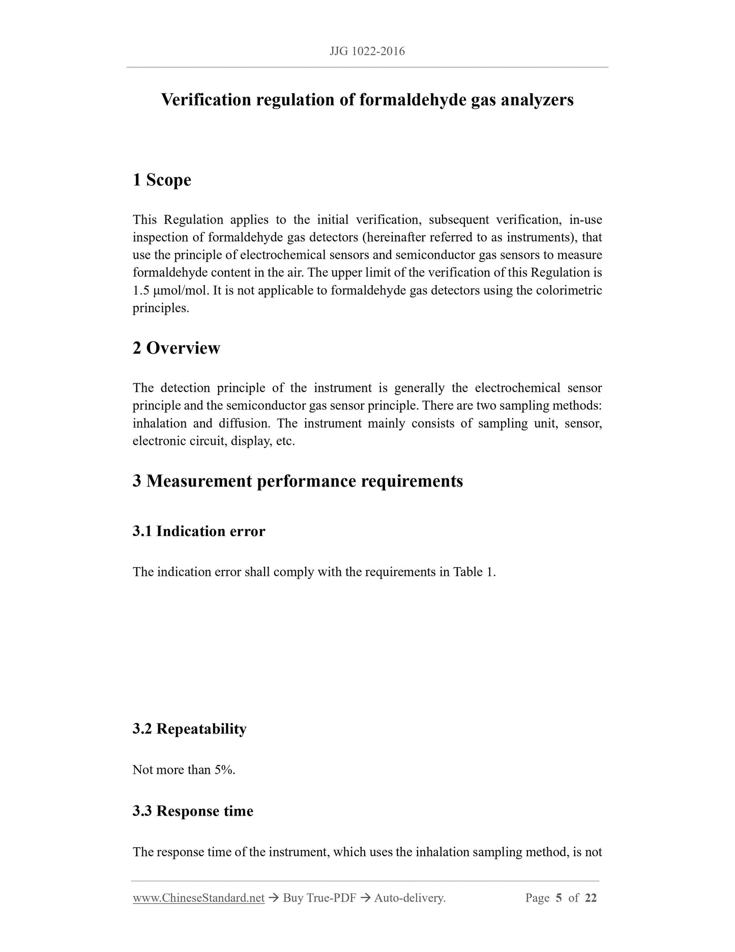
Scope
This Regulation applies to the initial verification, subsequent verification, in-useinspection of formaldehyde gas detectors (hereinafter referred to as instruments), that
use the principle of electrochemical sensors and semiconductor gas sensors to measure
formaldehyde content in the air. The upper limit of the verification of this Regulation is
1.5 μmol/mol. It is not applicable to formaldehyde gas detectors using the colorimetric
principles.
Basic Data
| Standard ID | JJG 1022-2016 (JJG1022-2016) |
| Description (Translated English) | Formaldehyde Gas Analyzers |
| Sector / Industry | Metrology and Measurement Industry Standard |
| Classification of Chinese Standard | A61 |
| Classification of International Standard | 17.020 |
| Word Count Estimation | 18,177 |
| Date of Issue | 2016-06-27 |
| Date of Implementation | 2016-12-27 |
| Older Standard (superseded by this standard) | JJG 1022-2007 |
| Regulation (derived from) | Notice of the General Administration of Quality Supervision, Inspection and Quarantine of the People Republic of China 2016 No.16 |
| Issuing agency(ies) | General Administration of Quality Supervision, Inspection and Quarantine |
| Summary | This standard applies to the use of electrochemical sensor principle, the principle of semiconductor gas sensor measurement of formaldehyde in the air content of formaldehyde gas detector (hereinafter referred to as the instrument) of the first test, follow-up inspection and use of inspection. The upper limit of this standard is 1.5 ��mol/mol. Does not apply to the colorimetric principle of formaldehyde gas detector. |
Share