JJG 0061-2001 English PDF (JJG0061-2001)
Regular price
$370.00 USD
Regular price
Sale price
$370.00 USD
Unit price
/
per
Delivery: 3 seconds. Download true-PDF + Invoice.
Get QUOTATION in 1-minute: Click JJG 0061-2001
Historical versions: JJG 0061-2001
Preview True-PDF (Reload/Scroll if blank)
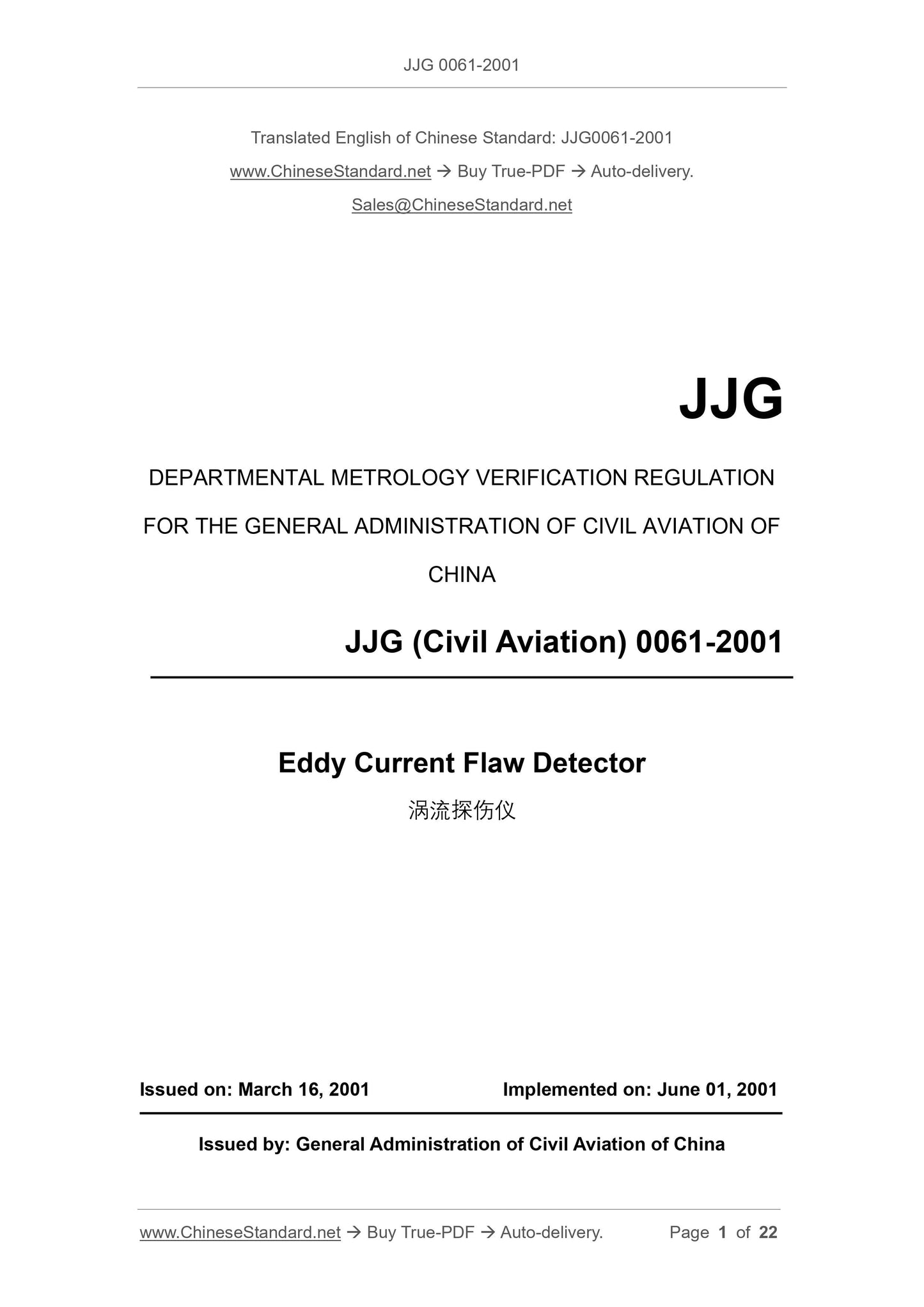
JJG 0061-2001: [JJG(MH) 0061-2001] Verification Regulation of Eddy Current Flaw Detector
JJG 0061-2001
JJG
DEPARTMENTAL METROLOGY VERIFICATION REGULATION
FOR THE GENERAL ADMINISTRATION OF CIVIL AVIATION OF
CHINA
JJG (Civil Aviation) 0061-2001
Eddy Current Flaw Detector
ISSUED ON: MARCH 16, 2001
IMPLEMENTED ON: JUNE 01, 2001
Issued by: General Administration of Civil Aviation of China
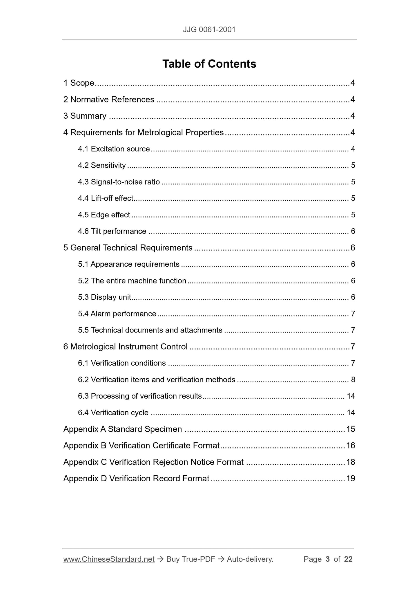
Table of Contents
1 Scope ... 4
2 Normative References ... 4
3 Summary ... 4
4 Requirements for Metrological Properties ... 4
4.1 Excitation source ... 4
4.2 Sensitivity ... 5
4.3 Signal-to-noise ratio ... 5
4.4 Lift-off effect ... 5
4.5 Edge effect ... 5
4.6 Tilt performance ... 6
5 General Technical Requirements ... 6
5.1 Appearance requirements ... 6
5.2 The entire machine function ... 6
5.3 Display unit ... 6
5.4 Alarm performance ... 7
5.5 Technical documents and attachments ... 7
6 Metrological Instrument Control ... 7
6.1 Verification conditions ... 7
6.2 Verification items and verification methods ... 8
6.3 Processing of verification results ... 14
6.4 Verification cycle ... 14
Appendix A Standard Specimen ... 15
Appendix B Verification Certificate Format ... 16
Appendix C Verification Rejection Notice Format ... 18
Appendix D Verification Record Format ... 19
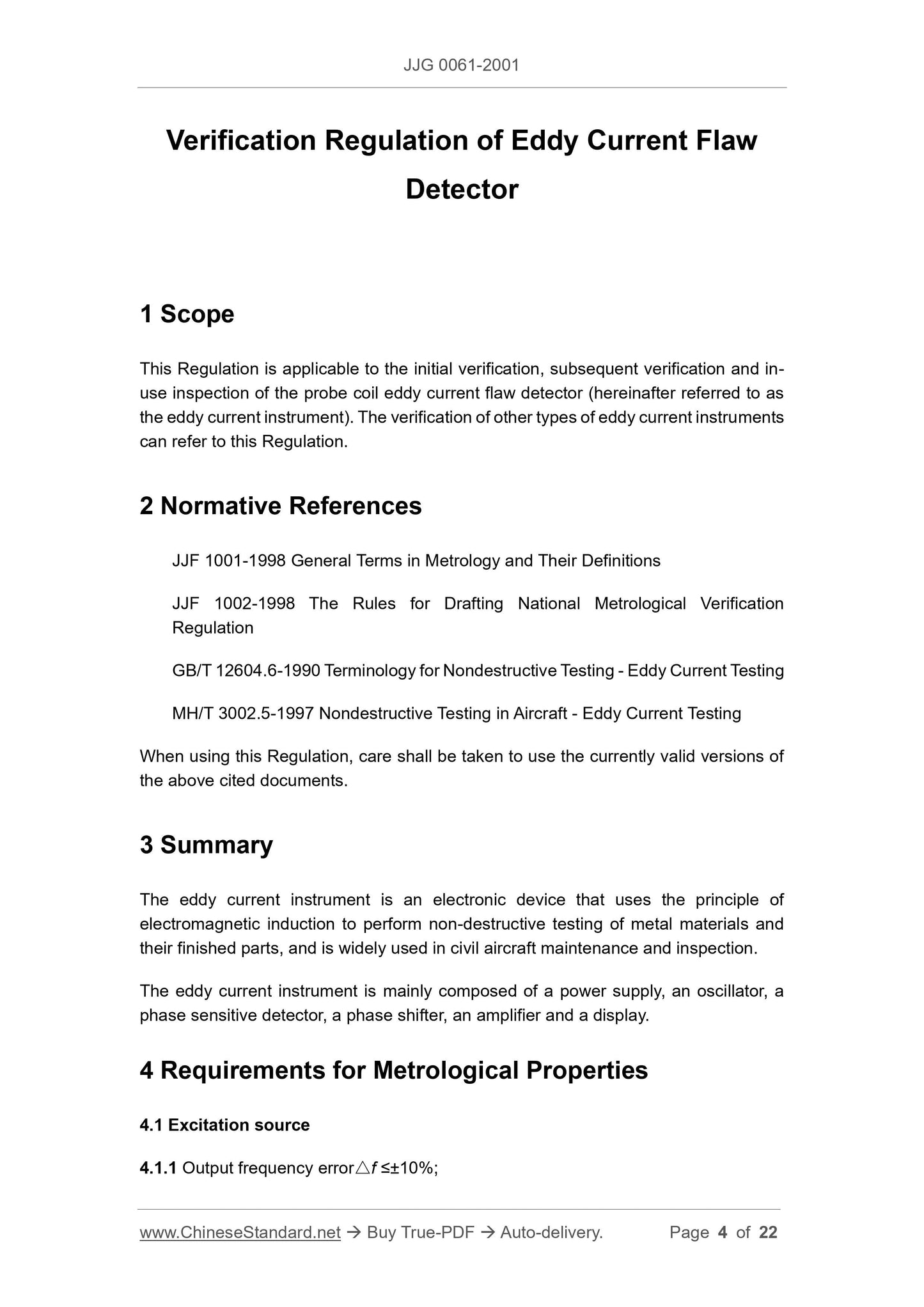
Verification Regulation of Eddy Current Flaw
Detector
1 Scope
This Regulation is applicable to the initial verification, subsequent verification and in-
use inspection of the probe coil eddy current flaw detector (hereinafter referred to as
the eddy current instrument). The verification of other types of eddy current instruments
can refer to this Regulation.
2 Normative References
JJF 1001-1998 General Terms in Metrology and Their Definitions
JJF 1002-1998 The Rules for Drafting National Metrological Verification
Regulation
GB/T 12604.6-1990 Terminology for Nondestructive Testing - Eddy Current Testing
MH/T 3002.5-1997 Nondestructive Testing in Aircraft - Eddy Current Testing
When using this Regulation, care shall be taken to use the currently valid versions of
the above cited documents.
3 Summary
The eddy current instrument is an electronic device that uses the principle of
electromagnetic induction to perform non-destructive testing of metal materials and
their finished parts, and is widely used in civil aircraft maintenance and inspection.
The eddy current instrument is mainly composed of a power supply, an oscillator, a
phase sensitive detector, a phase shifter, an amplifier and a display.
4 Requirements for Metrological Properties
4.1 Excitation source
4.1.1 Output frequency error△f ≤±10%;
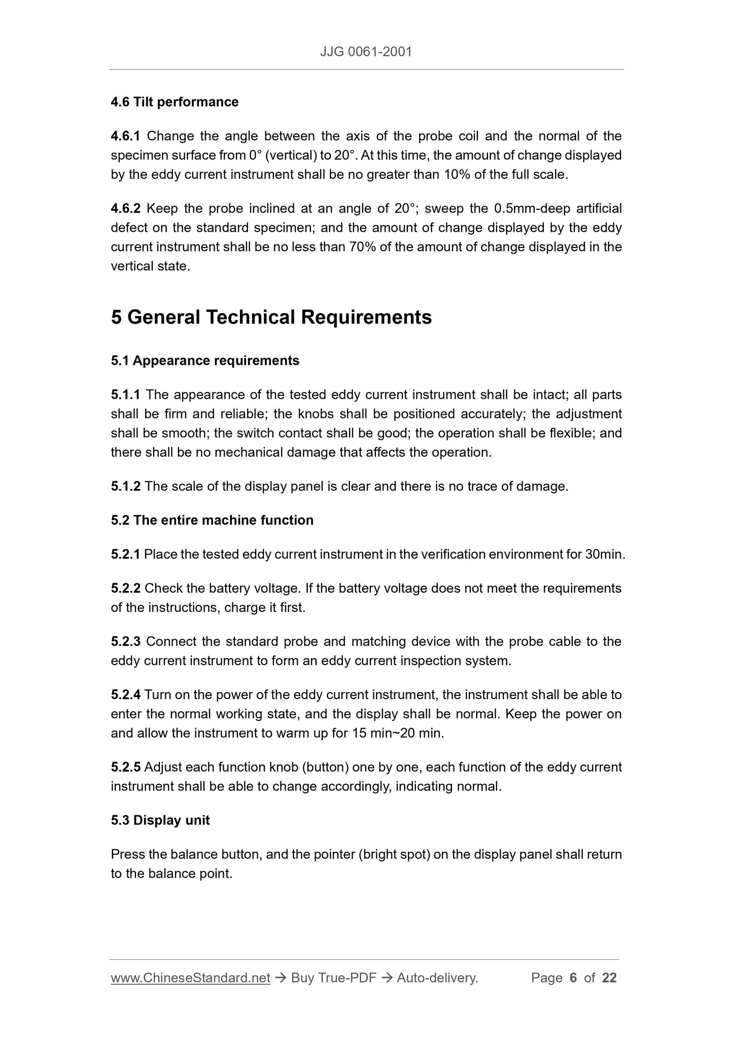
4.6 Tilt performance
4.6.1 Change the angle between the axis of the probe coil and the normal of the
specimen surface from 0° (vertical) to 20°. At this time, the amount of change displayed
by the eddy current instrument shall be no greater than 10% of the full scale.
4.6.2 Keep the probe inclined at an angle of 20°; sweep the 0.5mm-deep artificial
defect on the standard specimen; and the amount of change displayed by the eddy
current instrument shall be no less than 70% of the amount of change displayed in the
vertical state.
5 General Technical Requirements
5.1 Appearance requirements
5.1.1 The appearance of the tested eddy current instrument shall be intact; all parts
shall be firm and reliable; the knobs shall be positioned accurately; the adjustment
shall be smooth; the switch contact shall be good; the operation shall be flexible; and
there shall be no mechanical damage that affects the operation.
5.1.2 The scale of the display panel is clear and there is no trace of damage.
5.2 The entire machine function
5.2.1 Place the tested eddy current instrument in the verification environment for 30min.
5.2.2 Check the battery voltage. If the battery voltage does not meet the requirements
of the instructions, charge it first.
5.2.3 Connect the standard probe and matching device with the probe cable to the
eddy current instrument to form an eddy current inspection system.
5.2.4 Turn on the power of the eddy current instrument, the instrument shall be able to
enter the normal working state, and the display shall be normal. Keep the power on
and allow the instrument to warm up for 15 min~20 min.
5.2.5 Adjust each function knob (button) one by one, each function of the eddy current
instrument shall be able to change accordingly, indicating normal.
5.3 Display unit
Press the balance button, and the pointer (bright spot) on the display panel shall return
to the balance point.
6.1.2.4 Standard specimen (see Appendix A).
Standard specimens include aluminum specimens and steel specimens; and steel
specimens are suitable for verifying the "Fe" gear of the eddy current instrument.
6.1.3 Supporting equipment.
6.1.3.1 Standard probe.
It has passed the comprehensive performance inspection, is not worn and damaged,
and can be matched with the eddy current instrument.
6.1.3.2 Load resistance (R).
The rated resistance and non-inductive resistance specified by the manufacturer can
also use standard probes.
6.1.3.3 Low temperature test cabinet.
The size can store the eddy current instrument, the temperature shall be controlled at
0°C±5°C, with a temperature display, to ensure that the instrument is verified in a low
temperature state.
6.1.3.4 High temperature test chamber.
The size can store the eddy current instrument, the temperature shall be controlled at
40°C±5°C, with a temperature display, to ensure that the instrument is verified under
high temperature conditions.
6.1.3.5 Non-conductive materials.
PTFE film or other wear-resistant insulating film with a thickness of 0.05mm~0.10mm
and a thickness of 0.15mm can be stacked in multiple layers.
6.2 Verification items and verification methods
6.2.1 The verification items are shown in Table 1.
The comprehensive performance verification of the eddy current instrument is to
connect a standard probe to the eddy current instrument; make the standard probe
move at a normal and uniform speed; and keep a certain angle between the probe coil
axis and the sample surface. And move on the standard specimen according to the set
trajectory; so that verify the sensitivity, signal-to-noise ratio, lift-off effect, edge effect
and tilt performance of the eddy current instrument.
In the following verification, for the eddy current meter with variable frequency, shall
select the high, medium and low points in the usual frequency range for verification
respectively. For the eddy current meter with fixed frequency, the commonly used
gears (Fe, NFe) shall be verified, respectively. But for frequency points exceeding
3MHz, the 6.2.7.1d) and 6.2.7.5 verification items shall not be required.
When reading the amount of change displayed by the eddy current instrument, for the
instrument displayed on the impedance plane, the vertical component shall be read.
6.2.7.1 Sensitivity verification.
a) Place the probe on the part of the standard specimen without artificial defects
(i.e.: the specimen substrate); keep the probe coil axis perpendicular to the
specimen surface; and the distance between the center of the coil and the edge
of the specimen and artificial defects is no less than 10mm. Set the frequency
and phase of the eddy current instrument; adjust the gain of the eddy current
instrument to the maximum. If the electrical noise is too large at this time, the
gain shall be appropriately reduced until no obvious electrical noise appears.
b) Reduce ...