Skip to product information
1 of 9

PayPal, credit cards. Download editable-PDF and invoice in 1 second!

JG/T 125-2017 English PDF (JGT125-2017)

JG/T 125-2017 English PDF (JGT125-2017)

Regular price $215.00 USD
Regular price Sale price $215.00 USD
Sale Sold out
Shipping calculated at checkout.
Delivery: 3 seconds. Download true-PDF + Invoice.
Get QUOTATION in 1-minute: Click JG/T 125-2017
Historical versions: JG/T 125-2017
Preview True-PDF (Reload/Scroll if blank)

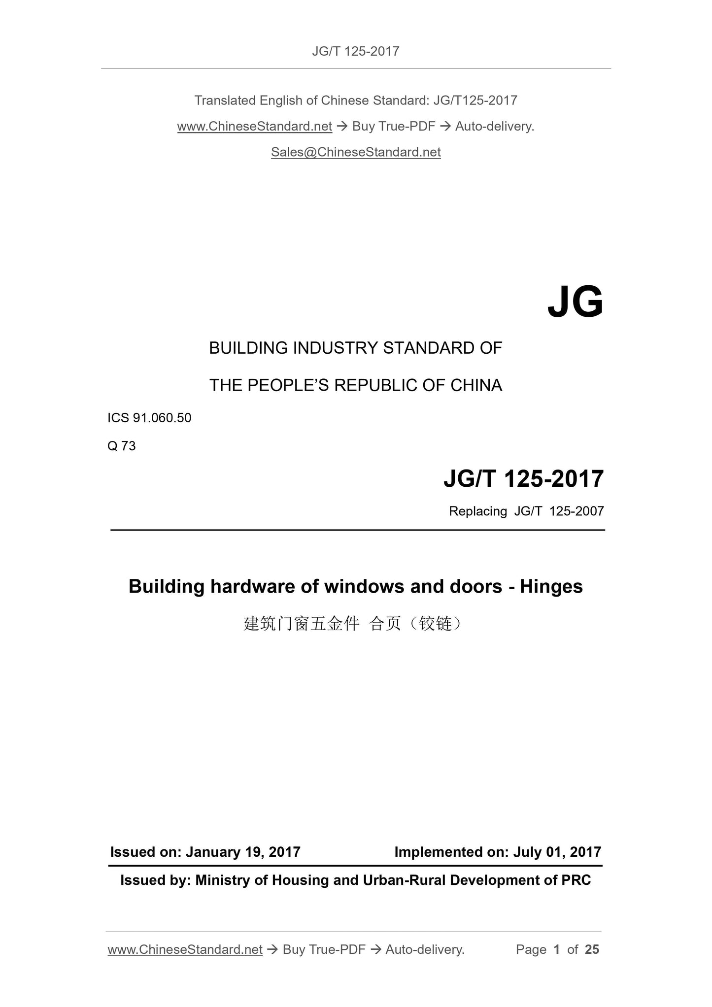
JG/T 125-2017: Building hardware of windows and doors. Hinges
JG/T 125-2017
JG
BUILDING INDUSTRY STANDARD OF
THE PEOPLE’S REPUBLIC OF CHINA
ICS 91.060.50
Q 73
Replacing JG/T 125-2007
Building hardware of windows and doors - Hinges
ISSUED ON: JANUARY 19, 2017
IMPLEMENTED ON: JULY 01, 2017
Issued by: Ministry of Housing and Urban-Rural Development of PRC
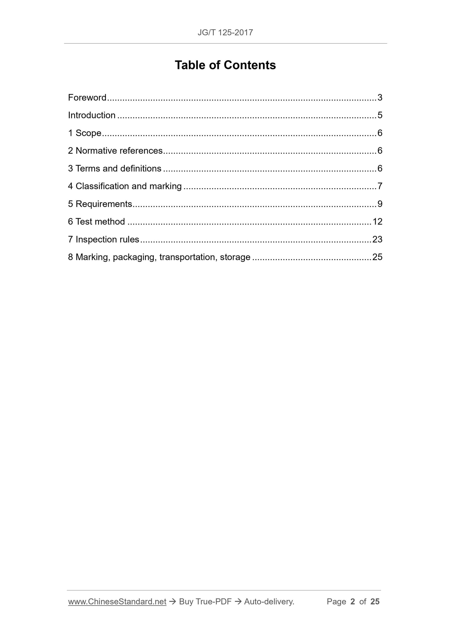
Table of Contents
Foreword ... 3 
Introduction ... 5 
1 Scope ... 6 
2 Normative references ... 6 
3 Terms and definitions ... 6 
4 Classification and marking ... 7 
5 Requirements ... 9 
6 Test method ... 12 
7 Inspection rules ... 23 
8 Marking, packaging, transportation, storage ... 25 
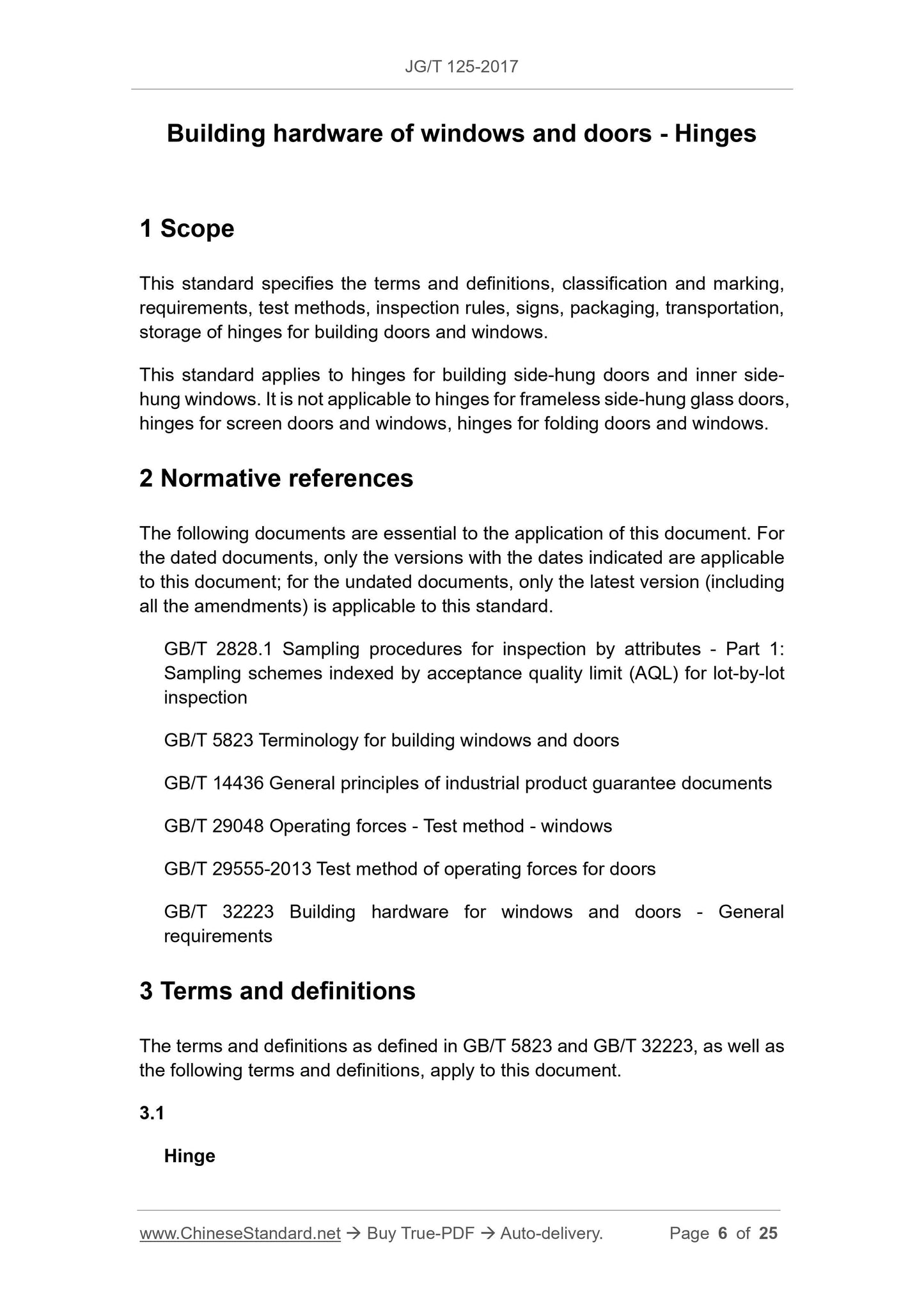
Building hardware of windows and doors - Hinges
1 Scope
This standard specifies the terms and definitions, classification and marking,
requirements, test methods, inspection rules, signs, packaging, transportation,
storage of hinges for building doors and windows.
This standard applies to hinges for building side-hung doors and inner side-
hung windows. It is not applicable to hinges for frameless side-hung glass doors,
hinges for screen doors and windows, hinges for folding doors and windows.
2 Normative references
The following documents are essential to the application of this document. For
the dated documents, only the versions with the dates indicated are applicable
to this document; for the undated documents, only the latest version (including
all the amendments) is applicable to this standard.
GB/T 2828.1 Sampling procedures for inspection by attributes - Part 1:
Sampling schemes indexed by acceptance quality limit (AQL) for lot-by-lot
inspection
GB/T 5823 Terminology for building windows and doors
GB/T 14436 General principles of industrial product guarantee documents
GB/T 29048 Operating forces - Test method - windows
GB/T 29555-2013 Test method of operating forces for doors
GB/T 32223 Building hardware for windows and doors - General
requirements
3 Terms and definitions
The terms and definitions as defined in GB/T 5823 and GB/T 32223, as well as
the following terms and definitions, apply to this document.
3.1
Hinge
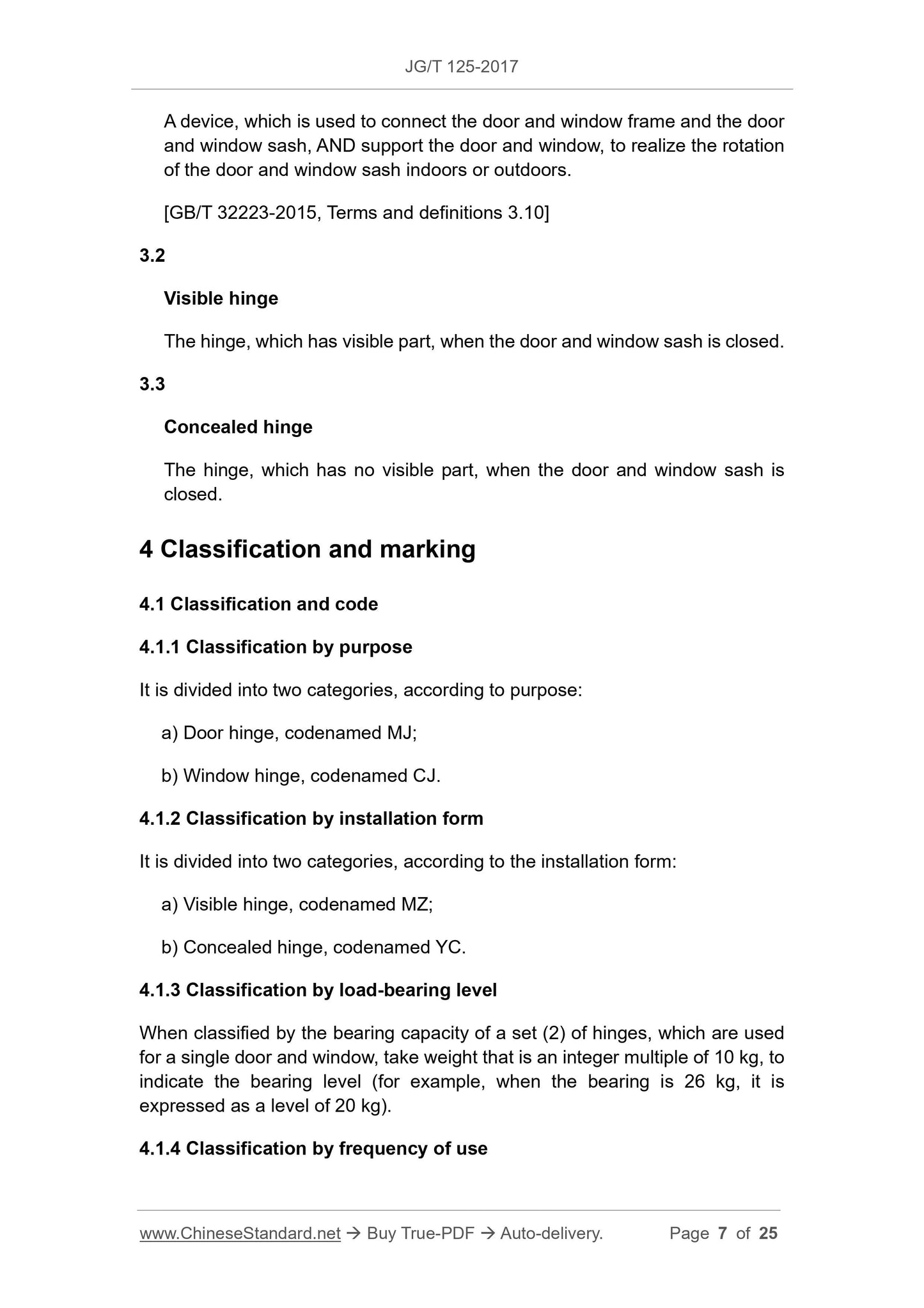
A device, which is used to connect the door and window frame and the door
and window sash, AND support the door and window, to realize the rotation
of the door and window sash indoors or outdoors.
[GB/T 32223-2015, Terms and definitions 3.10]
3.2
Visible hinge
The hinge, which has visible part, when the door and window sash is closed.
3.3
Concealed hinge
The hinge, which has no visible part, when the door and window sash is
closed.
4 Classification and marking
4.1 Classification and code
4.1.1 Classification by purpose
It is divided into two categories, according to purpose:
a) Door hinge, codenamed MJ;
b) Window hinge, codenamed CJ.
4.1.2 Classification by installation form
It is divided into two categories, according to the installation form:
a) Visible hinge, codenamed MZ;
b) Concealed hinge, codenamed YC.
4.1.3 Classification by load-bearing level
When classified by the bearing capacity of a set (2) of hinges, which are used
for a single door and window, take weight that is an integer multiple of 10 kg, to
indicate the bearing level (for example, when the bearing is 26 kg, it is
expressed as a level of 20 kg).
4.1.4 Classification by frequency of use
6.4 Mechanical properties
6.4.1 Rotation force
6.4.1.1 Door hinge with use frequency I
Install a set of hinges on the steel test simulated door. Apply the weight to the
load-bearing level. Open and close the door leaf 20 times. Follow the test
method of 8.1 in GB/T 29555-2013, to carry out the test, when the door leaf is
opened to 90° ± 5° OR the during the process of reaching to the design
maximum opening angle.
6.4.1.2 Visible door hinges with use frequency II, window hinges with use
frequency III
Install a set of hinges, on the test simulation door and window of corresponding
size, according to its actual load. The door hinge is tested, according to the test
method of GB/T 29555; the window hinge is tested, according to the test
method of GB/T 29048.
6.4.2 Load-bearing performance
6.4.2.1 Door hinge with use frequency I
For the door hinge specimen, with the use frequency I, after the test of the
rotational force performance, it is tested for the load-bearing performance,
according to the following requirements. The schematic diagram of the position
of the measurement point of the load deformation test, is as shown in Figure 5.
a) When loading to the load-bearing level, at the center of gravity of the door
leaf, record the horizontal distance h0 and the vertical distance v0;
b) After loading the door leaf, at the center of gravity, to 2 times the load-
bearing level AND opening and closing the door leaf 20 times, record the
horizontal distance h1 and vertical distance v1, after deformation;
c) Calculate the horizontal deformation Δh1, under the load-bearing level,
according to formula (1). Calculate the vertical deformation Δv1, under the
load-bearing level, according to formula (2);
d) After unloading, open and close the door for another 5 times. Then record
the horizontal distance h2 and vertical distance v2, after unloading and
recovery. Use the formula (3), to calculate the residual horizontal
deformation Δh2 after unloading. Use the formula (4), to calculate the
residual vertical deformation Δv2, after unloading;
Where:
Δh1 - The horizontal deformation, under 2 times the load-bearing level, in
millimeters (mm);
h1 - The horizontal distance, under 2 times the load-bearing level, in
millimeters (mm);
h0 - The horizontal distance, in the initial state, in millimeters (mm);
Where:
Δv1 - The vertical deformation, under 2 times the load-bearing level, in
millimeters (mm);
v1 - The vertical distance, under 2 times the load-bearing level, in
millimeters (mm);
v0 - The vertical distance, in the initial state, in millimeters (mm);
Where:
Δh2 - The horizontal residual deformation after unloading, in millimeters
(mm);
h2 - The horizontal distance after unloading, in millimeters (mm);
Where:
Δv2 - The vertical residual deformation after unloading, in millimeters (mm);
v2 - The vertical distance after unloading, in millimeters (mm).
e) Load 3 times the actual load-bearing weight, at the center of gravity of the
door leaf. After opening and closing the door leaf 5 times, keep it for 1 min
~ 2 min. After unloading, check the hinge for visible damage and cracks.
The whole process shall be completed, within 5 minutes.
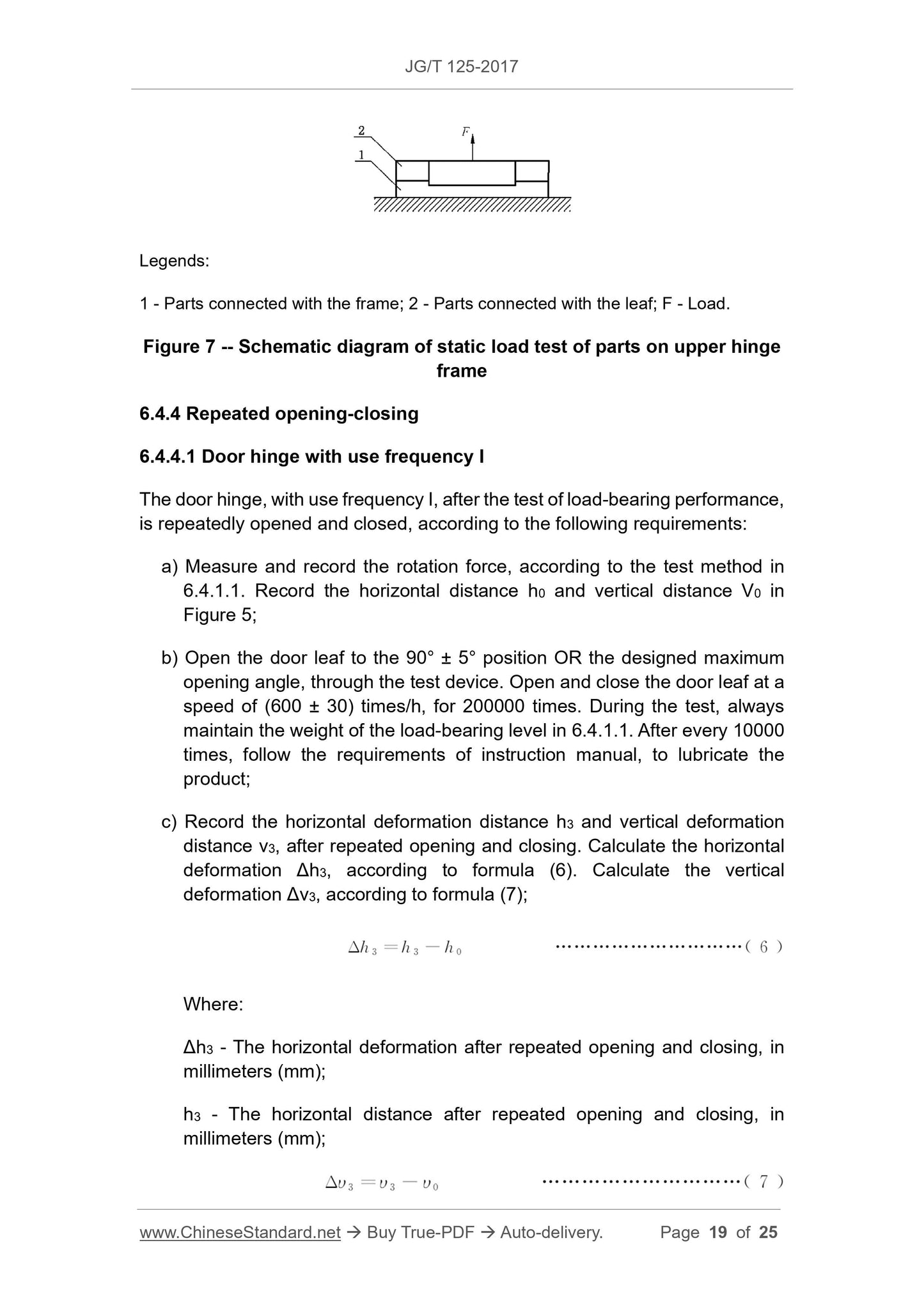
Legends:
1 - Parts connected with the frame; 2 - Parts connected with the leaf; F - Load.
Figure 7 -- Schematic diagram of static load test of parts on upper hinge
frame
6.4.4 Repeated opening-closing
6.4.4.1 Door hinge with use frequency I
The door hinge, with use frequency I, after the test of load-bearing performance,
is repeatedly opened and closed, according to the following requirements:
a) Measure and record the rotation force, according to the test method in
6.4.1.1. Record the horizontal distance h0 and vertical distance V0 in
Figure 5;
b) Open the door leaf to the 90° ± 5° position OR the designed maximum
opening angle, through the test device. Open and close the door leaf at a
speed of (600 ± 30) times/h, for 200000 times. During the test, always
maintain the weight of the load-bearing level in 6.4.1.1. After every 10000
times, follow the requirements of instruction manu...
View full details