1
/
of
10
www.ChineseStandard.us -- Field Test Asia Pte. Ltd.
JB/T 9023.1-2019 English PDF (JB/T9023.1-2019)
Regular price
$205.00
Regular price
Sale price
$205.00
Unit price
/
per
Shipping calculated at checkout.
Couldn't load pickup availability
JB/T 9023.1-2019: Downhole Drill - Part 1: Open-Cut Type
Delivery: 9 seconds. Download (& Email) true-PDF + Invoice.
Get Quotation: Click JB/T 9023.1-2019 (Self-service in 1-minute)
Historical versions (Master-website): JB/T 9023.1-2019
Preview True-PDF (Reload/Scroll-down if blank)
JB/T 9023.1-2019
JB
MACHINERY INDUSTRY STANDARD
ICS 73.100.30
D 92
Replacing JB/T 9023.1-1999
Downhole Drill – Part 1.Open-Cut Type
ISSUED ON. MAY 02, 2019
IMPLEMENTED ON. JANUARY 1, 2020
Issued by. Ministry of Industry and Information Technology of the People’s
Republic of China
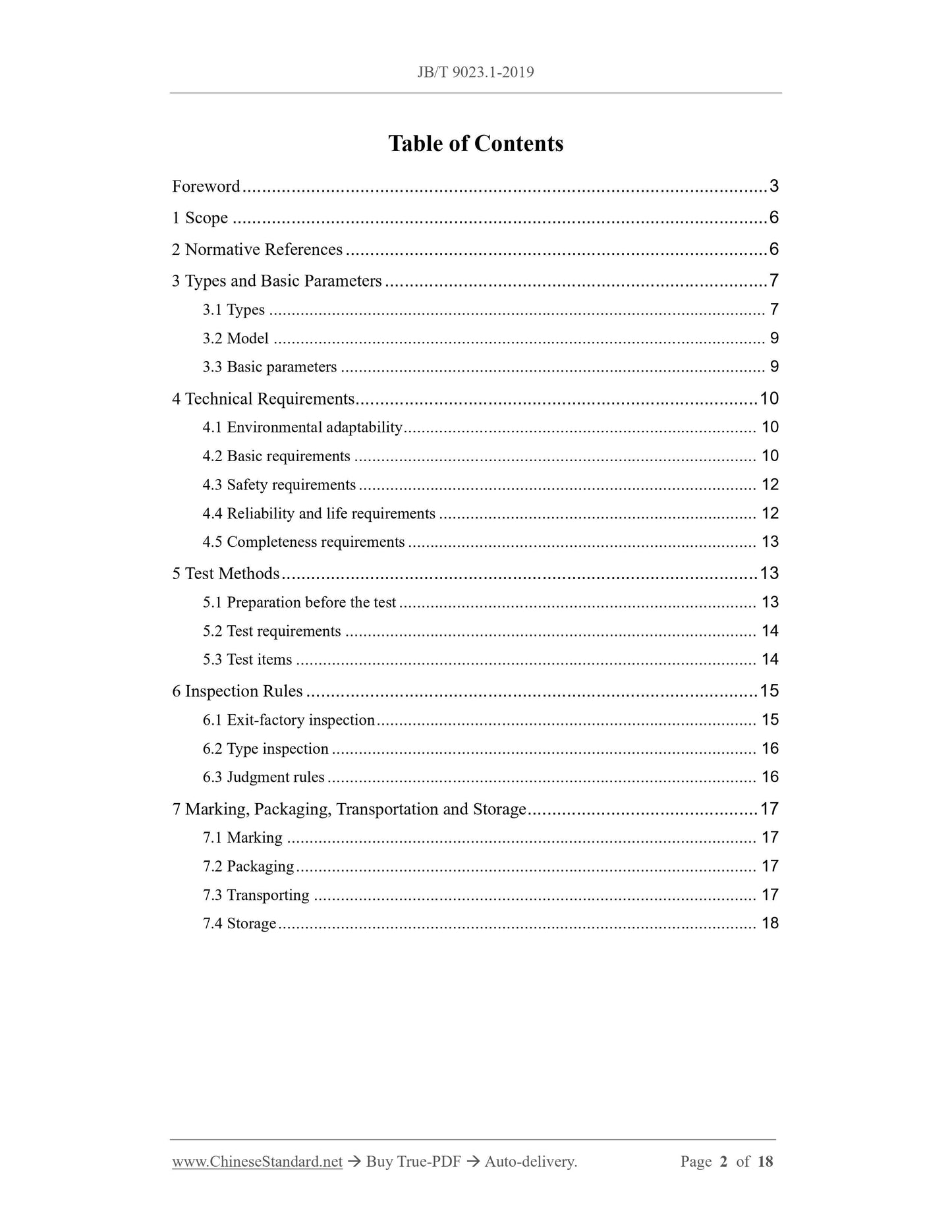
Table of Contents
Foreword... 3
1 Scope... 6
2 Normative References... 6
3 Types and Basic Parameters... 7
3.1 Types... 7
3.2 Model... 9
3.3 Basic parameters... 9
4 Technical Requirements... 10
4.1 Environmental adaptability... 10
4.2 Basic requirements... 10
4.3 Safety requirements... 12
4.4 Reliability and life requirements... 12
4.5 Completeness requirements... 13
5 Test Methods... 13
5.1 Preparation before the test... 13
5.2 Test requirements... 14
5.3 Test items... 14
6 Inspection Rules... 15
6.1 Exit-factory inspection... 15
6.2 Type inspection... 16
6.3 Judgment rules... 16
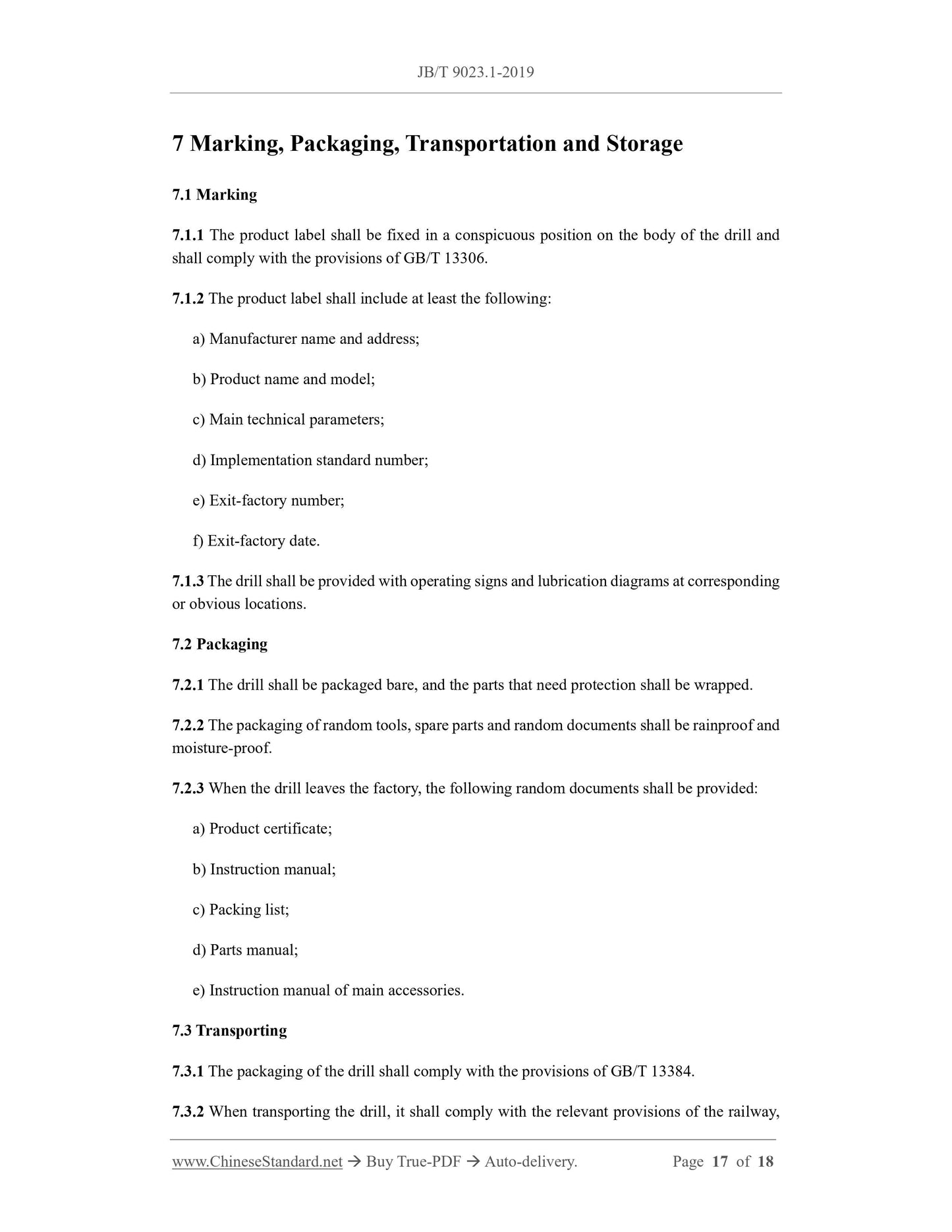
7 Marking, Packaging, Transportation and Storage... 17
7.1 Marking... 17
7.2 Packaging... 17
7.3 Transporting... 17
7.4 Storage... 18
Downhole Drill – Part 1.Open-Cut Type
1 Scope
This Part of JB/T 9023 specifies the types and basic parameters, technical requirements, test
methods, inspection rules, marking, packaging, transportation and storage of downhole drills
for open-cut type.
This Part is applicable to downhole drills (hereinafter referred to as drills) used for drilling
blasting holes in open-pit projects such as open-pit mining, water conservancy construction,
railway and national defense construction.
2 Normative References
The following documents are essential to the application of this Document. For the dated
documents, only the versions with the dates indicated are applicable to this Document; for the
undated documents, only the latest version (including all the amendments) is applicable to this
Document.
GB/T 156 Standard voltages
GB/T 3766 Hydraulic fluid power - General rules and safety requirements for systems and
their components
GB/T 4208-2017 Degrees of protection provided by enclosure (IP code)
GB/T 5226.1 Electrical safety of machinery - Electrical equipment of machines - Part 1.
General requirements
GB/T 7935 Hydraulic fluid power - General requirements for hydraulic components
GB/T 8196 Safety of machinery – Guards - General requirements for the design and
construction of fixed and movable guards
GB/T 8420 Earth-moving machinery - Human physical dimensions of operators and
minimum operator space envelope
GB/T 8593.1 Earth-moving machinery - Symbols for operator controls and other displays
- Part 1.Common symbols
GB/T 10095.1-2008 Cylindrical gears - System of accuracy - Part 1.Definitions and
allowable values of deviations relevant to corresponding flanks of gear teeth
GB/T 10095.2-2008 Cylindrical gears - System of accuracy - Part 2.Definitions and
allowable values of deviations relevant to radial composite deviations and runout
information
GB/T 13306 Plates
GB/T 13325 Noise emitted by machinery and equipment - Guideline for the preparation
of test codes of engineering grade requiring noise measurements at the operators or by
standers position
GB/T 13344 Downhole drill hammers and bits
GB/T 13384 General specifications for packing of mechanical and electrical product
GB/T 21153 Earth-moving machinery - Units for dimensions performance and capacities
and their measurement accuracies
GB/T 25706 Code of designations for mining machinery products
HJ 618-2011 Determination of atmospheric articles PM10 and PM2.5 in ambient air by
gravimetric method
JB/T 5943 Construction machinery - General specifications for welding parts
JB/T 5946 Construction machinery - General technical specifications for painting
JB/T 7165 Rock Drilling Machines and Pneumatic Tools - General Specifications for
Assembly
3 Types and Basic Parameters
3.1 Types
Drills are divided into electric motor driven drill or internal combustion engine driven drill
according to the driving mode. They use crawler tracks or tires to travel and rotary impact
drilling. Their basic structural type is shown in Figure 1.
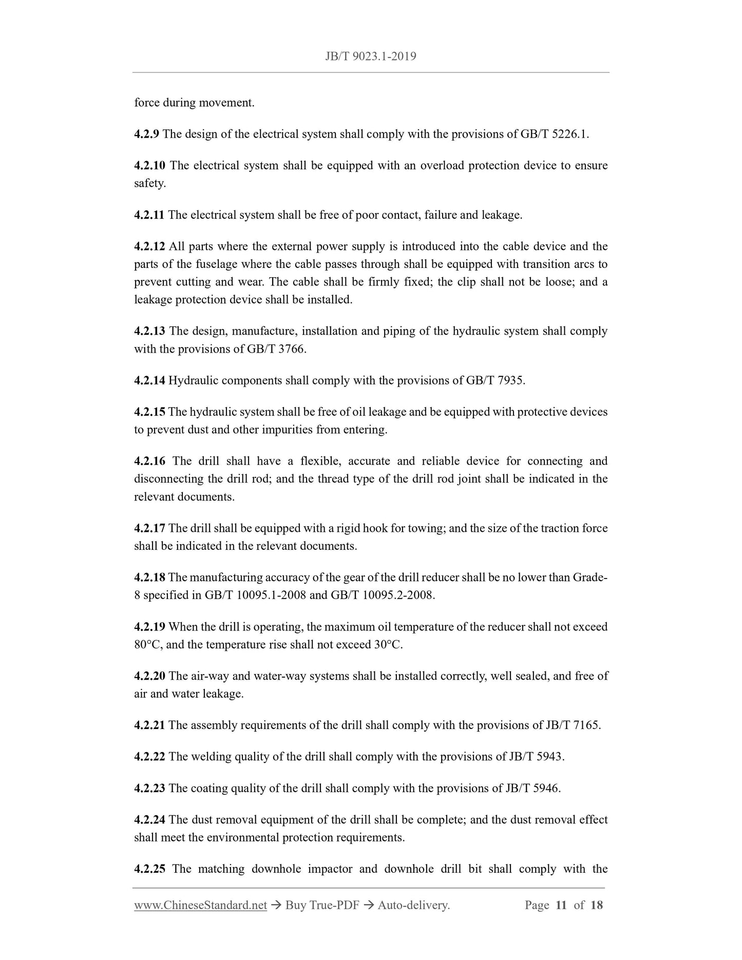
force during movement.
4.2.9 The design of the electrical system shall comply with the provisions of GB/T 5226.1.
4.2.10 The electrical system shall be equipped with an overload protection device to ensure
safety.
4.2.11 The electrical system shall be free of poor contact, failure and leakage.
4.2.12 All parts where the external power supply is introduced into the cable device and the
parts of the fuselage where the cable passes through shall be equipped with transition arcs to
prevent cutting and wear. The cable shall be firmly fixed; the clip shall not be loose; and a
leakage protection device shall be installed.
4.2.13 The design, manufacture, installation and piping of the hydraulic system shall comply
with the provisions of GB/T 3766.
4.2.14 Hydraulic components shall comply with the provisions of GB/T 7935.
4.2.15 The hydraulic system shall be free of oil leakage and be equipped with protective devices
to prevent dust and other impurities from entering.
4.2.16 The drill shall have a flexible, accurate and reliable device for connecting and
disconnecting the drill rod; and the thread type of the drill rod joint shall be indicated in the
relevant documents.
4.2.17 The drill shall be equipped with a rigid hook for towing; and the size of the traction force
shall be indicated in the relevant documents.
4.2.18 The manufacturing accuracy of the gear of the drill reducer shall be no lower than Grade-
8 specified in GB/T 10095.1-2008 and GB/T 10095.2-2008.
4.2.19 When the drill is operating, the maximum oil temperature of the reducer shall not exceed
80°C, and the temperature rise shall not exceed 30°C.
4.2.20 The air-way and water-way systems shall be installed correctly, well sealed, and free of
air and water leakage.
4.2.21 The assembly requirements of the drill shall comply with the provisions of JB/T 7165.
4.2.22 The welding quality of the drill shall comply with the provisions of JB/T 5943.
4.2.23 The coating quality of the drill shall comply with the provisions of JB/T 5946.
4.2.24 The dust removal equipment of the drill shall be complete; and the dust removal effect
shall meet the environmental protection requirements.
4.2.25 The matching downhole impactor and downhole drill bit shall comply with the
provisions of GB/T 13344.
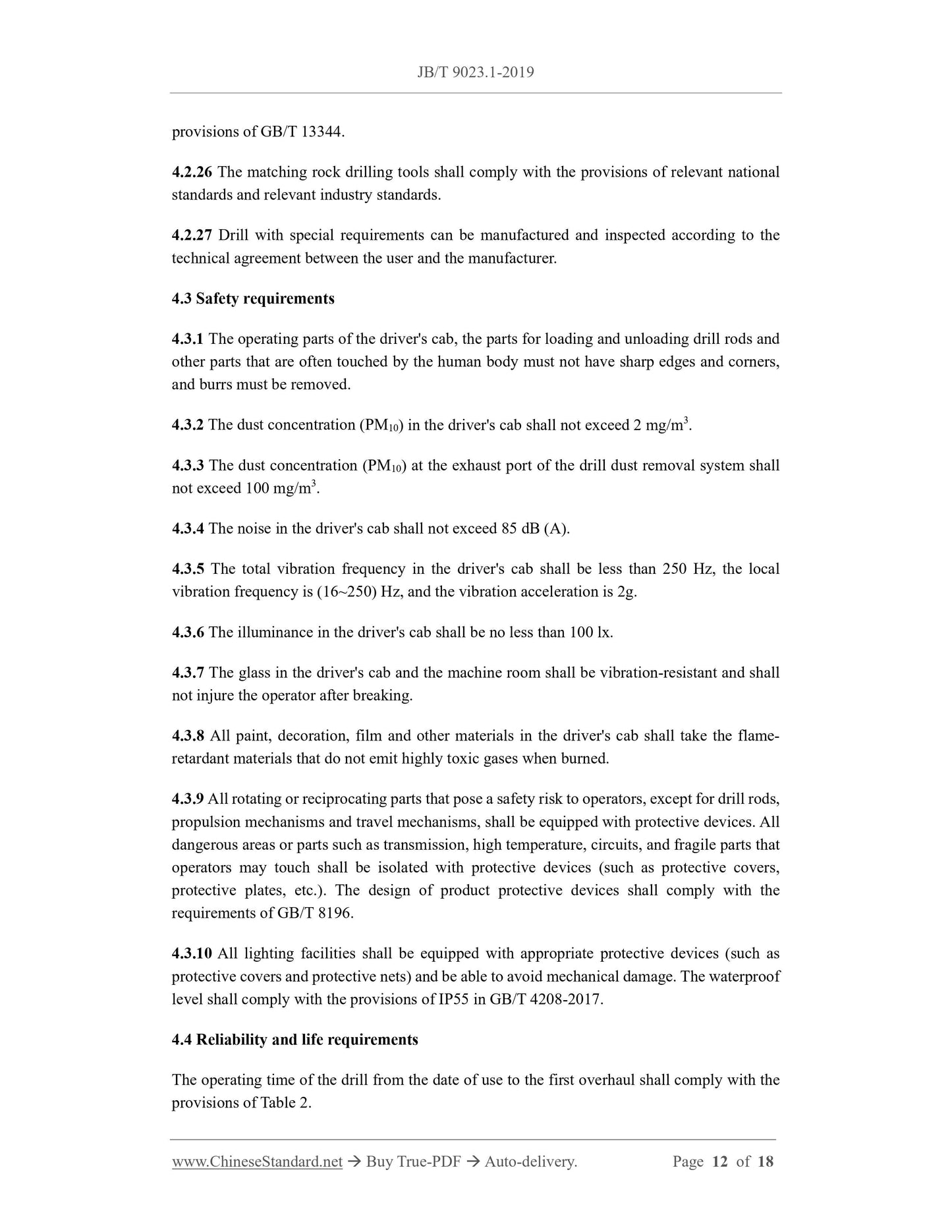
4.2.26 The matching rock drilling tools shall comply with the provisions of relevant national
standards and relevant industry standards.
4.2.27 Drill with special requirements can be manufactured and inspected according to the
technical agreement between the user and the manufacturer.
4.3 Safety requirements
4.3.1 The operating parts of the driver's cab, the parts for loading and unloading drill rods and
other parts that are often touched by the human body must not have sharp edges and corners,
and burrs must be removed.
4.3.2 The dust concentration (PM10) in the driver's cab shall not exceed 2 mg/m3.
4.3.3 The dust concentration (PM10) at the exhaust port of the drill dust removal system shall
not exceed 100 mg/m3.
4.3.4 The noise in the driver's cab shall not exceed 85 dB (A).
4.3.5 The total vibration frequency in the driver's cab shall be less than 250 Hz, the local
vibration frequency is (16~250) Hz, and the vibration acceleration is 2g.
4.3.6 The illuminance in the driver's cab shall be no less than 100 lx.
4.3.7 The glass in the driver's cab and the machine room shall be vibration-resistant and shall
not injure the operator after breaking.
4.3.8 All paint, decoration, film and other materials in the driver's cab shall take the flame-
retardant materials that do not emit highly toxic gases when burned.
4.3.9 All rotating or reciprocating parts that pose a safety risk to operators, except for drill rods,
propulsion mechanisms and travel mechanisms, shall be equipped with protective devices. All
dangerous areas or parts such as transmission, high temperature, circuits, and fragile parts that
operators may touch shall be isolated with protective devices (such as protective covers,
protective plates, etc.). The design of product protective devices shall comply with the
requirements of GB/T 8196.
4.3.10 All lighting facilities shall be equipped with appropriate protective devices (such as
protective covers and protective nets) and be able to avoid mechanical damage. The waterproof
level shall comply with the provisions of IP55 in GB/T 4208-2017.
4.4 Reliability and life requirements
The operating time of the drill from the date of use to the first overhaul shall comply with the
provisions of Table 2.
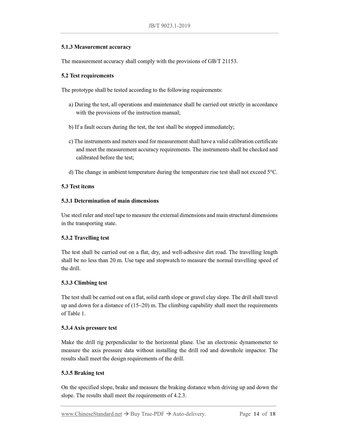
5.1.3 Measurement accuracy
The measurement accuracy shall comply with the provisions of GB/T 21153.
5.2 Test requirements
The prototype shall be tested according to the following requirements.
a) During the test, all operations and maintenance shall be carried out strictly in accordance
with the provisions of the instruction manual;
b) If a fault occurs during the test, the test shall be stopped immediately;
c) The instruments and meters used for measurement shall have a valid calibration certificate
and meet the measurement accuracy requirements. The instruments shall be checked and
calibrated before the test;
d) The change in ambient temperature during the temperature rise test shall not exceed 5°C.
5.3 Test items
5.3.1 Determination of main dimensions
Use steel ruler and steel tape to measure the external dimensions and main structural dimensions
in the transporting state.
5.3.2 Travelling test
The test shall be carried out on a flat, dry, and well-adhesive dirt road. The travelling length
shall be no less than 20 m. Use tape and stopwatch to measure the normal travelling speed of
the drill.
5.3.3 Climbing test
The test shall be carried out on a flat, solid earth slope or gravel clay slope. The drill shall travel
up and down for a distance of (15~20) m. The climbing capability shall meet the requirements
of Table 1.
5.3.4 Axis pressure test
Make the drill rig perpendicular to the horizontal plane. Use an electronic dynamometer to
measure the axis pressure data without installing the drill rod and downhole impactor. The
results shall meet the design requirements of the drill.
5.3.5 Braking test
On the specified slope, brake and measure the braking distance when driving up and down the
slope. The results shall meet the requirements of 4.2.3.
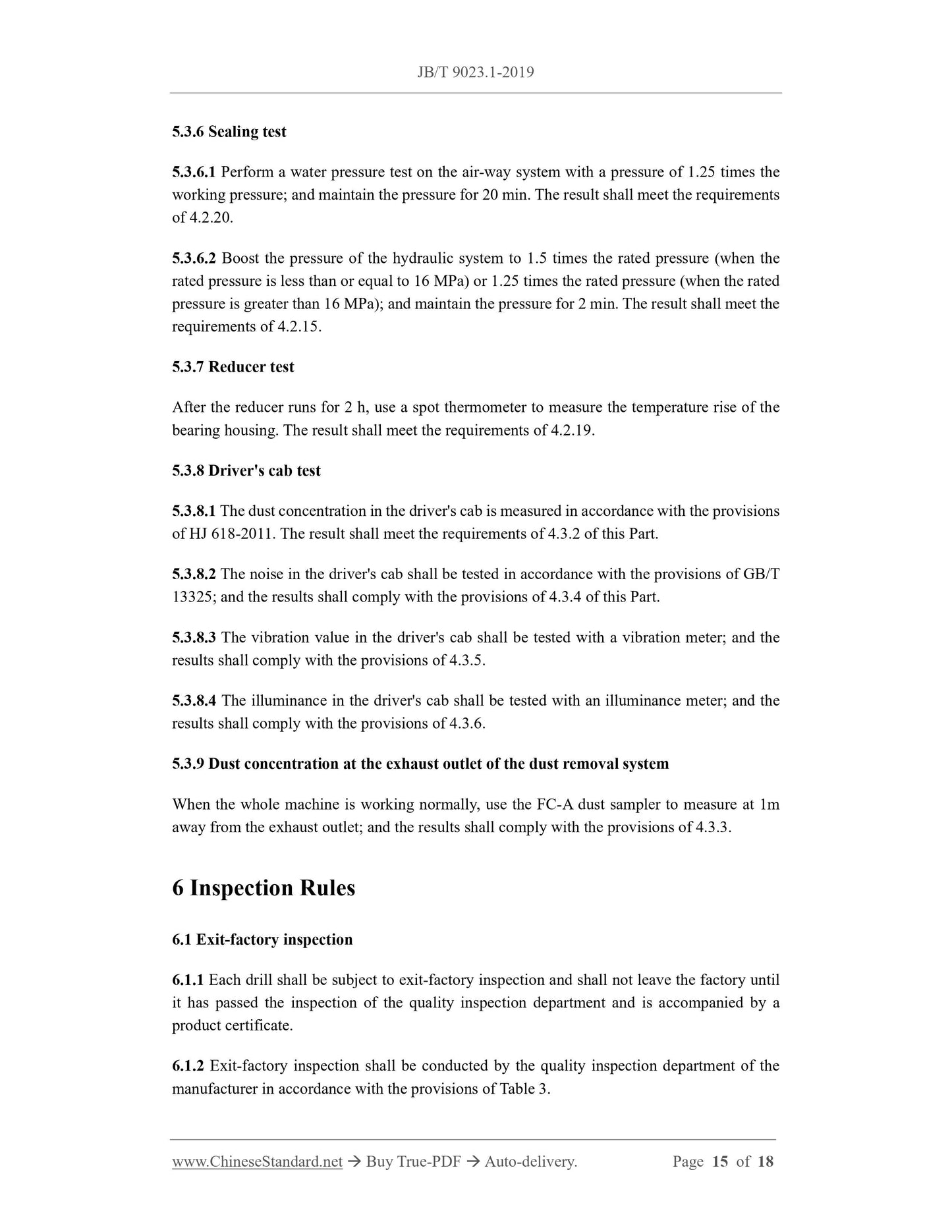
5.3.6 Sealing test
5.3.6.1 Perform a water pressure test on the air-way system with a pressure of 1.25 times the
working pressure; and maintain the pressure for 20 min. The result shall meet the requirements
of 4.2.20.
5.3.6.2 Boost the pressure of the hydraulic system to 1.5 times the rated pressure (when the
rated pressure is less than or equal to 16 MPa) or 1.25 times the rated pressure (when the rated
pressure is greater than 16 MPa); and maintain the pressure for 2 min. The result shall meet the
requirements of 4.2.15.
5.3.7 Reducer test
After the reducer runs for 2 h, use a spot thermometer to measure the temperature rise of the
bearing housing. The result shall meet the requirements of 4.2.19.
5.3.8 Driver's cab test
5.3.8.1 The dust concentration in the driver's cab is measured in accordance with the provisions
of HJ 618-2011.The result shall meet the requirements of 4.3.2 of this Part.
5.3.8.2 The noise in the driver's cab shall be tested in accordance with the provisions of GB/T
13325; and the results shall comply with the provisions of 4.3.4 of this Part.
5.3.8.3 The vibration value in the driver's cab shall be tested with a vibration meter; and the
results shall comply with the provisions of 4.3.5.
5.3.8.4 The illuminance in the driver's cab shall be tested with an illuminance meter; and the
results shall comply with the provisions of 4.3.6.
5.3.9 Dust concentration at the exhaust outlet of the dust removal system
When the whole machine is working normally, use the FC-A dust sampler to measure at 1m
away from the exhaust outlet; and the results shall comply with the provisions of 4.3.3.
6 Inspection Rules
6.1 Exit-factory inspection
6.1.1 Each drill shall be subject to exit-factory inspection and shall not leave the factory until
it has passed the inspection of the quality inspection department and is accompanied by a
product certificate.
6.1.2 Exit-factory inspection shall be conducted by the quality inspection department of the
manufacturer in accordance with the provisions of Table 3.
7 Marking, Packaging, Transportation and Storage
7.1 Marking
7.1.1 The product label shall be fixed in a conspicuous position on the body of the drill and
shall comply with the provisions of GB/T 13306.
7.1.2 The product label shall include at least the following.
a) Manufacturer name and address;
b) Product name and model;
c) Main technical parameters;
d) Implementation standard number;
e) Exit-factory number;
f) Exit-factory date.
7.1.3 The drill shall be provided with operating signs and lubrication diagrams at corresponding
or obvious locations.
7.2 Packaging
7.2.1 The drill shall be packaged bare, and the parts that need protection shall be wrapped.
7.2.2 The packaging of random tools, spare parts and random documents shall be rainproof and
moisture-proof.
7.2.3 When the drill leaves the factory, the following random documents shall be provided.
a) Product certificate;
b) Instruction manual;
c) Packing list;
d) Parts manual;
e) Instruction manual of main accessories.
7.3 Transporting
7.3.1 The packaging of the drill shall comply with the provisions of GB/T 13384.
7.3.2 When transporting the drill, it shall comply with the relevant provisions of the railway,
JB/T 9023.1-2019
JB
MACHINERY INDUSTRY STANDARD
ICS 73.100.30
D 92
Replacing JB/T 9023.1-1999
Downhole Drill – Part 1.Open-Cut Type
ISSUED ON. MAY 02, 2019
IMPLEMENTED ON. JANUARY 1, 2020
Issued by. Ministry of Industry and Information Technology...
Share