Skip to product information
1 of 10

PayPal, credit cards. Download editable-PDF & invoice in 1 second!

JB/T 9008.2-2015 English PDF (JBT9008.2-2015)

JB/T 9008.2-2015 English PDF (JBT9008.2-2015)

Regular price $290.00 USD
Regular price Sale price $290.00 USD
Sale Sold out
Shipping calculated at checkout.
Quotation: In 1-minute, 24-hr self-service. Click here JB/T 9008.2-2015 to get it for Purchase Approval, Bank TT...

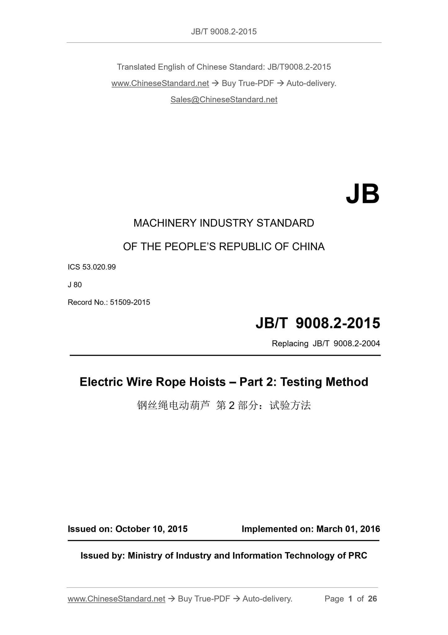
JB/T 9008.2-2015: Electric wire rope hoists. Part 2: Testing method

This Part of JB/T 9008 specifies the basic test requirements and the test contents and methods of each test for electric wire rope hoists. This Part is applicable to electric wire rope hoists that use or lift molten metal in a general environment. The electric hoists that are used in other environments can be referred to.
JB/T 9008.2-2015
JB
MACHINERY INDUSTRY STANDARD
OF THE PEOPLE’S REPUBLIC OF CHINA
ICS 53.020.99
J 80
Record No.: 51509-2015
Replacing JB/T 9008.2-2004
Electric Wire Rope Hoists – Part 2: Testing Method
ISSUED ON: OCTOBER 10, 2015
IMPLEMENTED ON: MARCH 01, 2016
Issued by: Ministry of Industry and Information Technology of PRC
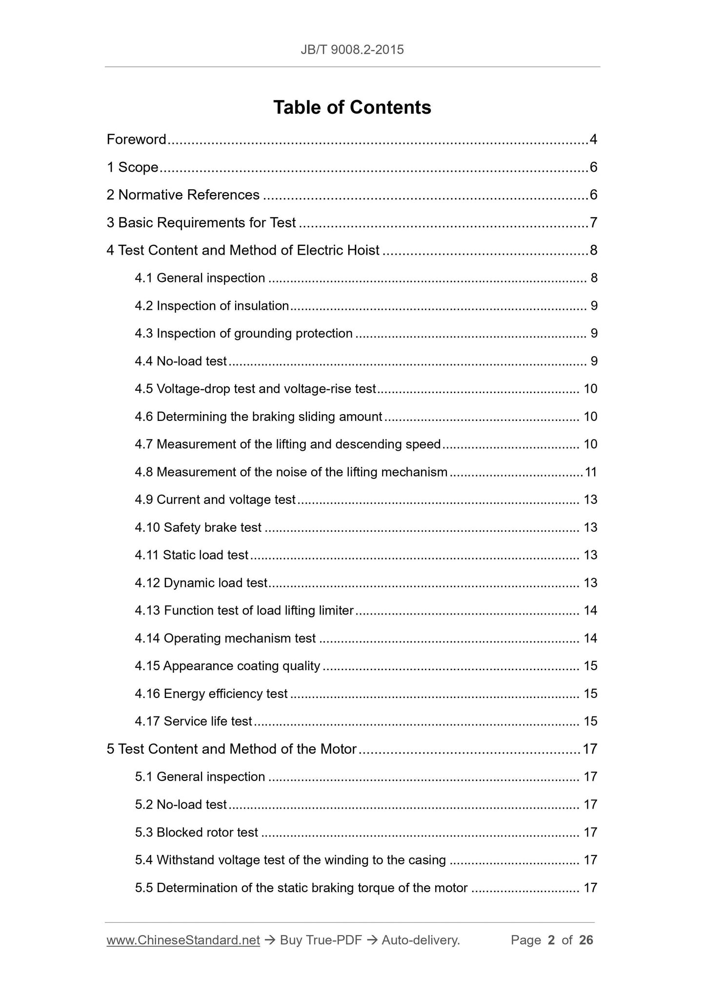
Table of Contents
Foreword ... 4
1 Scope ... 6
2 Normative References ... 6
3 Basic Requirements for Test ... 7
4 Test Content and Method of Electric Hoist ... 8
4.1 General inspection ... 8
4.2 Inspection of insulation ... 9
4.3 Inspection of grounding protection ... 9
4.4 No-load test ... 9
4.5 Voltage-drop test and voltage-rise test ... 10
4.6 Determining the braking sliding amount ... 10
4.7 Measurement of the lifting and descending speed ... 10
4.8 Measurement of the noise of the lifting mechanism ... 11
4.9 Current and voltage test ... 13
4.10 Safety brake test ... 13
4.11 Static load test ... 13
4.12 Dynamic load test ... 13
4.13 Function test of load lifting limiter ... 14
4.14 Operating mechanism test ... 14
4.15 Appearance coating quality ... 15
4.16 Energy efficiency test ... 15
4.17 Service life test ... 15
5 Test Content and Method of the Motor ... 17
5.1 General inspection ... 17
5.2 No-load test ... 17
5.3 Blocked rotor test ... 17
5.4 Withstand voltage test of the winding to the casing ... 17
5.5 Determination of the static braking torque of the motor ... 17
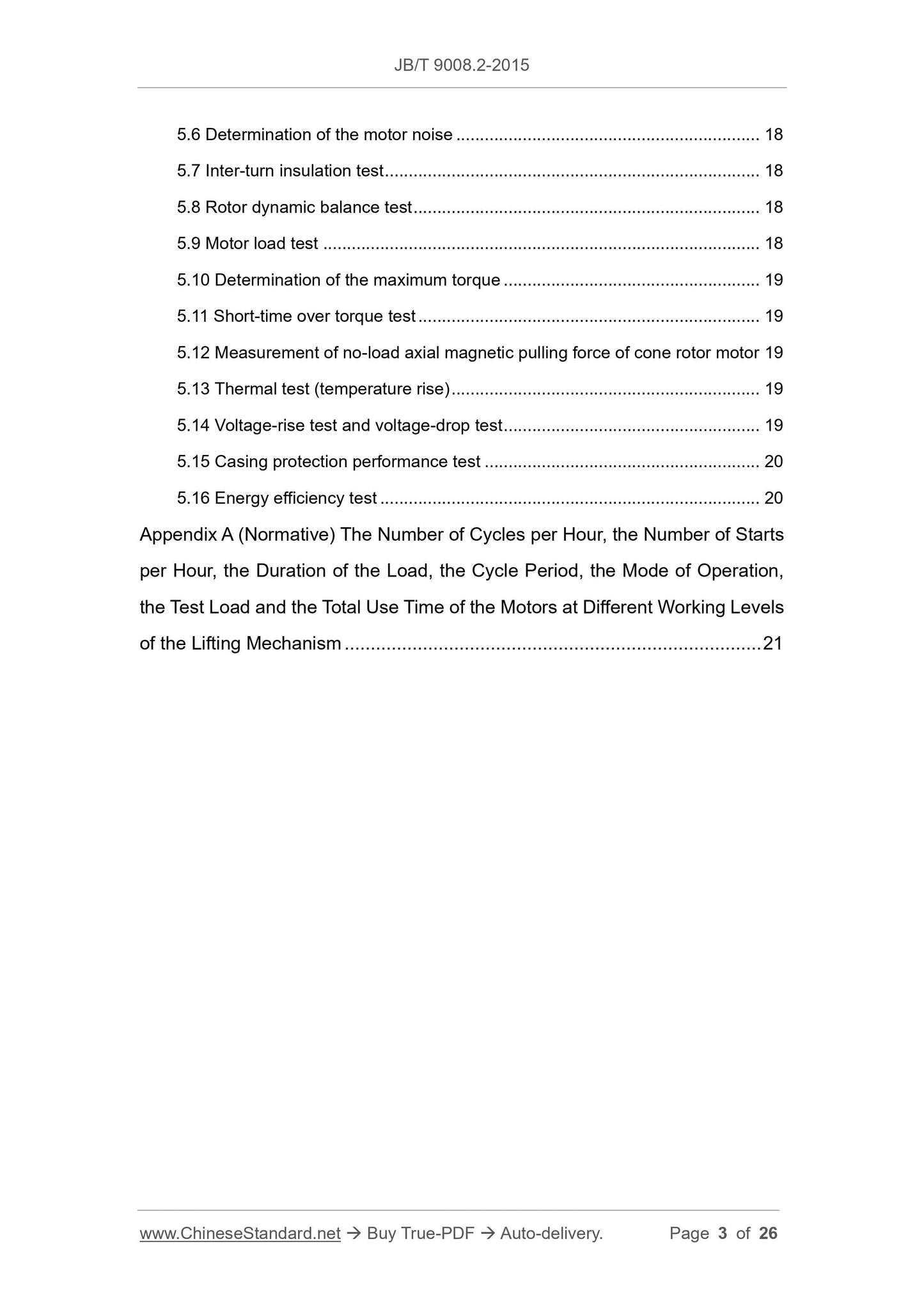
5.6 Determination of the motor noise ... 18
5.7 Inter-turn insulation test ... 18
5.8 Rotor dynamic balance test ... 18
5.9 Motor load test ... 18
5.10 Determination of the maximum torque ... 19
5.11 Short-time over torque test ... 19
5.12 Measurement of no-load axial magnetic pulling force of cone rotor motor 19 5.13 Thermal test (temperature rise) ... 19
5.14 Voltage-rise test and voltage-drop test ... 19
5.15 Casing protection performance test ... 20
5.16 Energy efficiency test ... 20
Appendix A (Normative) The Number of Cycles per Hour, the Number of Starts per Hour, the Duration of the Load, the Cycle Period, the Mode of Operation, the Test Load and the Total Use Time of the Motors at Different Working Levels of the Lifting Mechanism ... 21
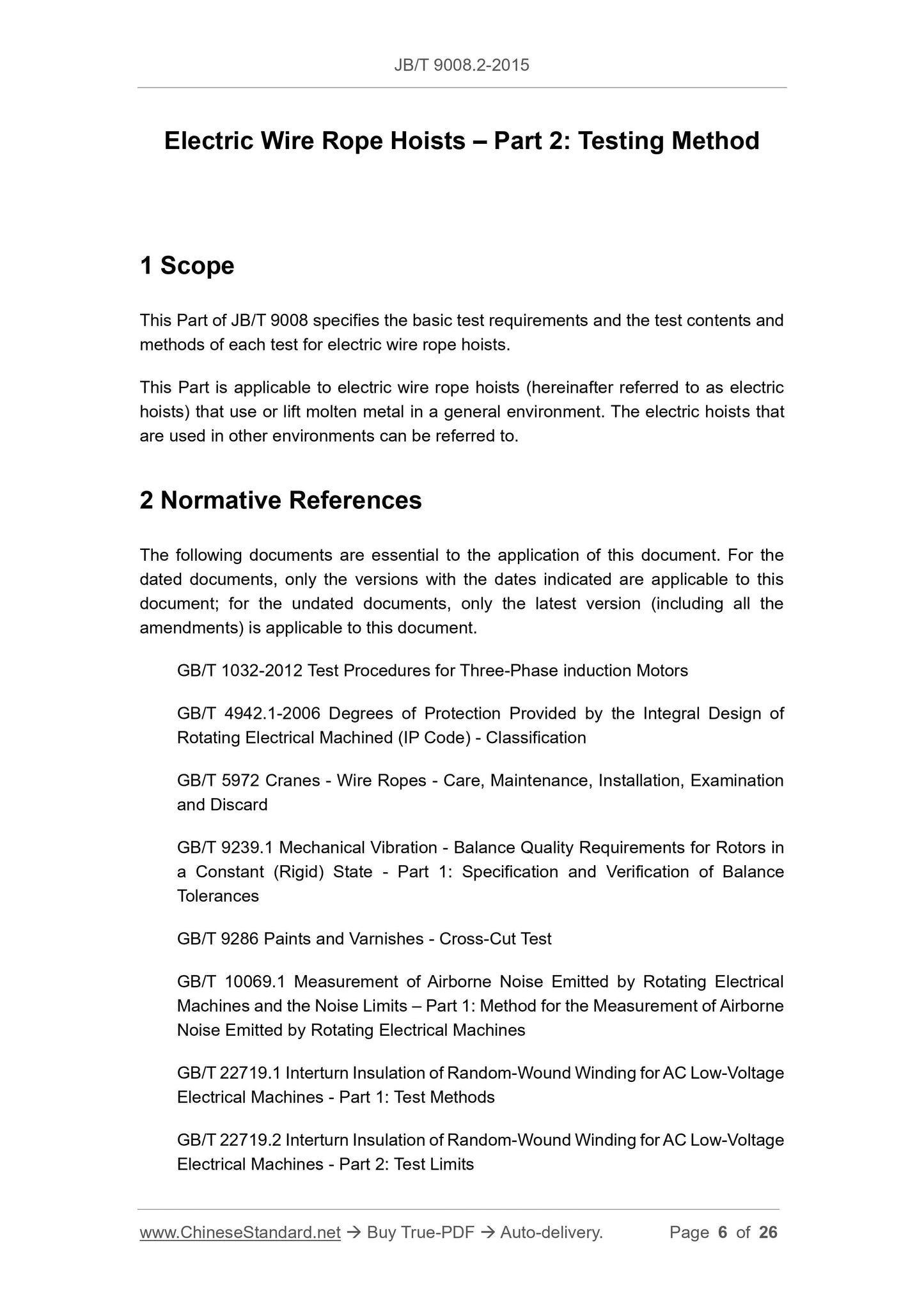
Electric Wire Rope Hoists – Part 2: Testing Method
1 Scope
This Part of JB/T 9008 specifies the basic test requirements and the test contents and methods of each test for electric wire rope hoists.
This Part is applicable to electric wire rope hoists (hereinafter referred to as electric hoists) that use or lift molten metal in a general environment. The electric hoists that are used in other environments can be referred to.
2 Normative References
The following documents are essential to the application of this document. For the dated documents, only the versions with the dates indicated are applicable to this document; for the undated documents, only the latest version (including all the amendments) is applicable to this document.
GB/T 1032-2012 Test Procedures for Three-Phase induction Motors
GB/T 4942.1-2006 Degrees of Protection Provided by the Integral Design of Rotating Electrical Machined (IP Code) - Classification
GB/T 5972 Cranes - Wire Ropes - Care, Maintenance, Installation, Examination and Discard
GB/T 9239.1 Mechanical Vibration - Balance Quality Requirements for Rotors in a Constant (Rigid) State - Part 1: Specification and Verification of Balance Tolerances
GB/T 9286 Paints and Varnishes - Cross-Cut Test
GB/T 10069.1 Measurement of Airborne Noise Emitted by Rotating Electrical Machines and the Noise Limits – Part 1: Method for the Measurement of Airborne Noise Emitted by Rotating Electrical Machines
GB/T 22719.1 Interturn Insulation of Random-Wound Winding for AC Low-Voltage Electrical Machines - Part 1: Test Methods
GB/T 22719.2 Interturn Insulation of Random-Wound Winding for AC Low-Voltage Electrical Machines - Part 2: Test Limits
GB/T 30028 Energy Efficiency Test Methods for Electrical Hoists
GB/T 29562.3 Energy Efficiency Test Procedures of Motors for Crane - Part 3: Conical Rotor 3-Phase Asynchronous Motors
JB/T 9008.1 Electric Wire Rope Hoists - Part 1: Types and Basic Parameter, Specification
3 Basic Requirements for Test
3.1 In addition to the test methods specified in this Part, other advanced and reliable test methods are allowed to be adopted.
3.2 The test power supply shall be consistent with the design power supply of the electric wire rope hoist. The sinusoidal distortion rate of the voltage waveform shall not exceed 5%; and the difference between the frequency of the test power supply and the rated frequency shall be within ±1%.
3.3 Measuring instruments and measuring tools shall be qualified and within the validity period of the verification. The selection of accuracy grade and range shall be able to meet the technical requirements of the test piece; and the specific requirements are as follows:
a) The accuracy of the voltmeter shall be no less than Level-0.5;
b) The accuracy of the ammeter shall be no less than Level-0.5;
c) The accuracy of the three-phase wattmeter shall be no less than Level-1; d) The accuracy of the transformer for measuring instrument shall be no less than Level-0.2;
e) The reading error of the tachometer is within ±1 r/min; and the accuracy of the digital tachometer and slip rate measuring instrument shall be no less than 0.1% ± 1 character;
f) The accuracy of the torque measuring instrument (including dynamometer and sensor) shall be no less than Level-0.5;
g) The accuracy of the dynamometer shall be no lower than Level-1.0;
h) The allowable deviation of the thermometer is ±1°C;
i) The allowable deviation of the test load is ±1%;
j) When the test instrument uses a computer automatic test system, the accuracy c) Start the lifting mechanism to lower the hook; rotate the drum for two revolutions; and check whether the wire rope can be discharged from the drum freely. 4.5 Voltage-drop test and voltage-rise test
Before the voltage-drop test, adjust the voltage at the motor terminal to 90% of the rated voltage; make the rated load start for three times in the air, with a total stroke of about 2m. And then raise the two-speed electric hoist slowly again, and check whether the electric hoist starts and operate normally.
Before voltage-rise test, adjust the voltage at the motor terminal to 110% of the rated voltage; make the rated load start for three times in the air, with the total stroke is about 2 m. And then raise the two-speed electric hoist slowly again, and check whether the electric hoist starts and operate normally.
4.6 Determining the braking sliding amount
There are many methods to measure the braking sliding amount, two methods are recommended. When there is an objection, Method-1 shall be used as the arbitration method.
Method-1: Under the conditions of rated voltage, rated frequency and rated load, use a reflective laser displacement sensor to continuously detect the position of the load. When the load drops to a certain position at the rated speed; a stop signal is given; and the test system marks the load position. After the load is stopped steadily, the test system marks the end position of the load braking; and the system calculates the difference between the two, which is the brake sliding amount. Measure three times continuously and take the average value.
Method-2: Under the conditions of rated voltage, rated frequency and rated load, use a steel wire rope with a diameter of 1mm. One end is tied to a small mound; and the other end is connected with a fixed micro switch (with normally-closed contact). The normally-closed contact is connected to the descending road controlled by a contactor. The mass of the mound shall be sufficient to make the switch act and cut off the descending circuit. During the measurement, the mound is placed on the load. When the load drops to a certain position at the rated speed, the mound is separated from the load. At this time, the descending circuit is immediately cut off, and the load starts to slide down immediately. The vertical distance between the mound and the load is the sliding amount; continuously measure for 3 times, and take the average value. 4.7 Measurement of the lifting and descending speed
Under the conditions of rated voltage, rated frequency and rated load, measure the lifting and lowering speeds.
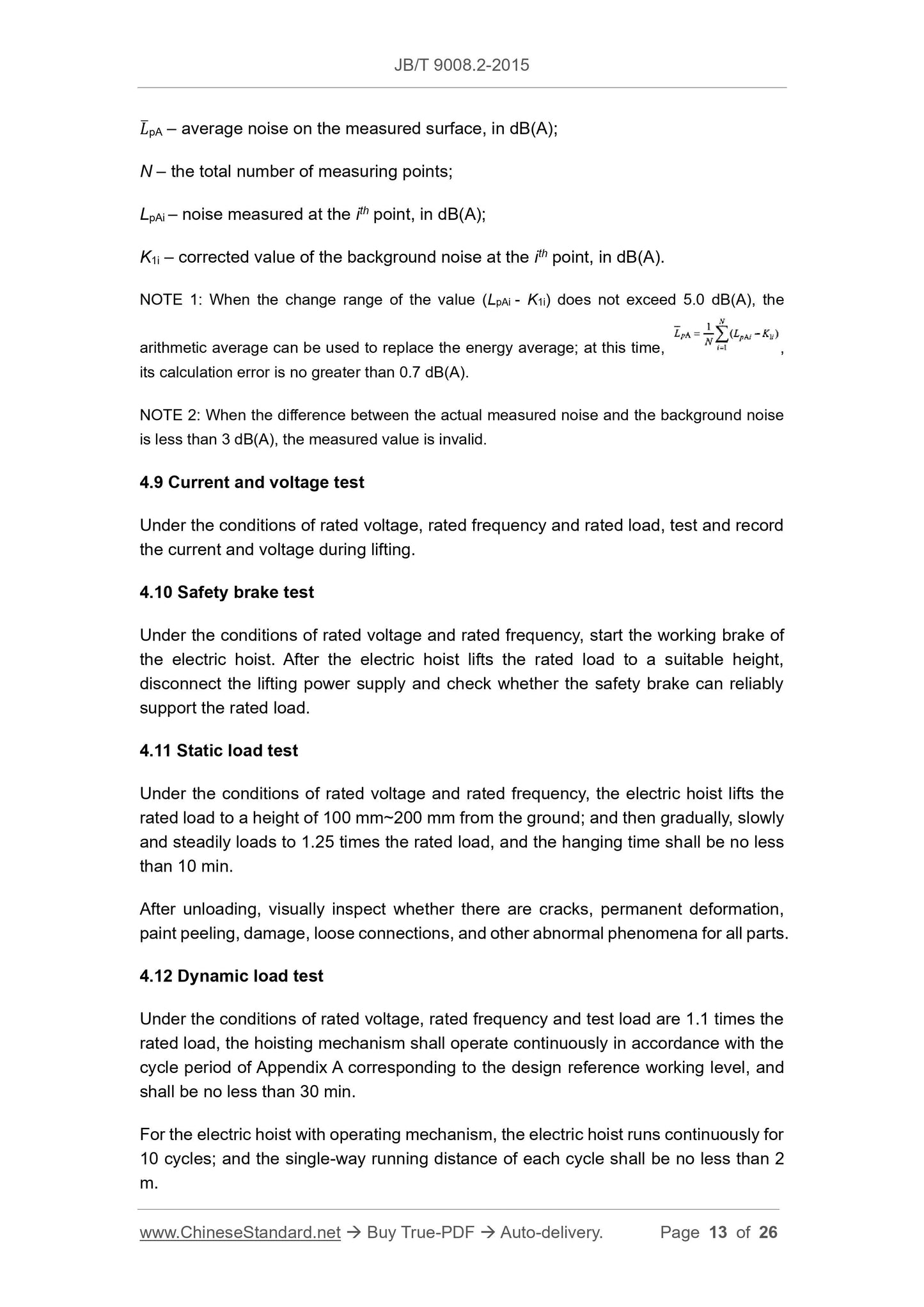
Lifting speed: When the lifting distance exceeds 0.5 m, use a stopwatch to measure ̅pA – average noise on the measured surface, in dB(A);
N – the total number of measuring points;
LpAi – noise measured at the ith point, in dB(A);
K1i – corrected value of the background noise at the ith point, in dB(A). NOTE 1: When the change range of the value (LpAi - K1i) does not exceed 5.0 dB(A), the arithmetic average can be used to replace the energy average; at this time, , its calculation error is no greater than 0.7 dB(A).
NOTE 2: When the difference between the actual measured noise and the background noise is less than 3 dB(A), the measured value is invalid.
4.9 Current and voltage test
Under the conditions of rated voltage, rated frequency and rated load, test and record the current and voltage during lifting.
4.10 Safety brake test
Under the conditions of rated voltage and rated frequency, start the working brake of the electric hoist. After the electric hoist lifts the rated load to a suitable height, disconnect the lifting power supply and check whether the safety brake can reliably support the rated load.
4.11 Static load test
Under the conditions of rated voltage and rated frequency, the electric hoist lifts the rated load to a height of 100 mm~200 mm from the ground; and then gradually, slowly and steadily loads to 1.25 times the rated load, and the hanging time shall be no less than 10 min.
After unloading, visually inspect whether there are cracks, permanent deformation, paint peeling, damage, loose connections, and other abnormal phenomena for all parts. 4.12 Dynamic load test
Under the conditions of rated voltage, rated frequency and test load are 1.1 times the rated load, the hoisting mechanism shall operate continuously in accordance with the cycle period of Appendix A corresponding to the design reference working level, and shall be no less than 30 min.
For the electric hoist with operating mechanism, the electric hoist runs continuously for 10 cycles; and the single-way running distance of each cycle shall be no less than 2 m.
After unloading, visually inspect whether there are cracks, permanent deformation, paint peeling, damage, loose connections, and other abnormal phenomena for all parts. NOTE: For electric hoist equipped with load lifting limiter, when carrying out static load test and dynamic load test, the load lifting limiter shall be unprotected before the test. 4.13 Function test of load lifting limiter
Under the conditions of rated voltage, rated frequency and rated load, check whether the electric hoist can lift normally.
Increase the actual lifting load to 110% of the rated lifting load; directly lift the load; and check whether the load lifting limiter can cut off the lifting power supply and stop lifting. At this time, measure the lifting distance of the load and check whether the lifting mechanism can do the descending movement.
4.14 Operating mechanism test
4.14.1 Operating test
Under the rated voltage and rated frequency, the electric hoist shall reciprocate on the track for no less than 2 times, and the stroke shall not be less than 2m each time when there is no load and under rated load.
4.14.2 Determining the operating speed
Under the conditions of rated voltage, rated frequency and rated load, the test shall be carried out on the track. The track shall be flat, and the static deflection in the middle of the track shall be less than L/1000 (L - the distance between the fulcrums of the track).
During the test, mark two points on the track that are no less than 2 m apart. When the electric hoist operates normally to one mark, it will start timing; and when it operates to the other mark, it will stop timing. The operating speed is calculated by calculation, and it is repeatedly measured for four times and take the average value. 4.14.3 Climbing test of operating mechanism
Under the conditions of rated voltage, rated frequency and rated load, the electric hoist will reciprocate three times on a track with a slope of 1/200, each one-way stroke is at least 2 m, and check whether it can work normally.
If the test is performed on a horizontal track, a force shall be applied in the opposite direction of operation, the magnitude of which is equal to 1/200 of the sum of the mass of the hoist and the rated load.
2 – lowest position for the descending of the test load.
Figure 2
4.17.3 Under the rated voltage and rated frequency of the hoisting mechanism, the service life test shall be carried out according to the working cycle and total service time of appendix A as per the working level and test load determined by the test plan. In the single-speed electric hoist test, the load shall fall to the ground once every twelve cycles; in the two-speed electric hoist test, the load should fall to the ground once every four cycles; after every sixteen cycles, the load shall be lifted directly after the load has fallen to the ground. During the test, the change in load duration caused by the falling to the ground of the load is negligible.
If the motor has reached a thermally stable state during the test, the motor can be tested through improving the load duration and the number of starts under thermally stable conditions through external cooling, so that achieve the purpose of shortening the test time.
4.17.4 During the test, perform normal maintenance according to the requirements of the instruction manual, and make the following inspection records:
a) When operating for 1h, test and record the noise and brake sliding amount, respectively.
b) The oil shall be changed after the operation reaches 50h. During other service life tests, the oil shall be changed according to the requirements of the instruction manual.
c) When the test operating time reaches 25%, 50%, 75% and 100% of the total use time specified in Appendix A, stop, dismantle and check the wear, fatigue and related performance indicators of all relative movement contact parts, and make records (for example: record the temperature rise and current of the electric motor before stopping; the noise, slippage and lubrication condition of the electric hoist; measure or check the wearing amount of the brake friction disk after stopping; the wear, fatigue and lubrication of the reducer gear; and the wearing amount of the drum and pulley, etc.).
d) The rejection of steel wire rope shall be treated in accordance with the provisions of GB/T 5972.
e) During the inspection, the brake friction disk must be replaced if one of the following conditions occurs:
• Cracks;
• The wearing amount of the thickness of the brake friction disk has reached 50% of the original thickness;
• The braking surface is uneven up to 1.5mm.
4.17.5 During all the tests, no parts shall be replaced except for steel wire ropes and brake friction disks.
5 Test Content and Method of the Motor
5.1 General inspection
5.1.1 Visual inspection: Whether the coating on the painted surface is uniform and colour consistent.
5.1.2 Whether the installation dimensions and tolerances meet the design requirements.
5.1.3 Whether there is any abnormal sound when the motor is operating.
5.1.4 The method for measuring the insulation resistance between the winding and the casing and the inter-windings shall be in accordance with the provisions in 5.1 of GB/T 1032-2012.
5.1.5 The method for measuring the DC terminal resistance of the winding in the actual cold state shall be in accordance with the provisions in 5.2 of GB/T 1032-2012. 5.2 No-load test
The no-load test method is in accordance with the provisions of Clause 8 of GB/T 1032- 2012.
5.3 Blocked rotor test
The blocked rotor test method is in accordance with the provisions in Clause 9 of GB/T 1032-2012.
5.4 Withstand voltage test of the winding to the casing
The test method for withstand voltage of the winding to the casing shall be in accordance with the provisions of 12.6 in GB/T 1032-2012. The test voltage is in accordance with JB/T 9008.1.
5.5 Determination of the static braking torque of the motor
As shown in Figure 3, use a special tool to connect the tube dynamometer to the shaft end of the motor; and apply a force perpendicular to the special tool to the tube dynamometer slowly and steadily until the motor shaft rotates. Then take the reading of the dynamometer at the moment when the motor shaft begins to rotate. Calculate

View full details