Skip to product information
1 of 10

PayPal, credit cards. Download editable-PDF and invoice in 1 second!

JB/T 7065-2015 English PDF (JB/T7065-2015)

JB/T 7065-2015 English PDF (JB/T7065-2015)

Regular price $145.00
Regular price Sale price $145.00
Sale Sold out
Shipping calculated at checkout.
JB/T 7065-2015: Pressure relief device for transformers
Delivery: 9 seconds. Download (& Email) true-PDF + Invoice.
Get Quotation: Click JB/T 7065-2015 (Self-service in 1-minute)
Historical versions (Master-website): JB/T 7065-2015
Preview True-PDF (Reload/Scroll-down if blank)

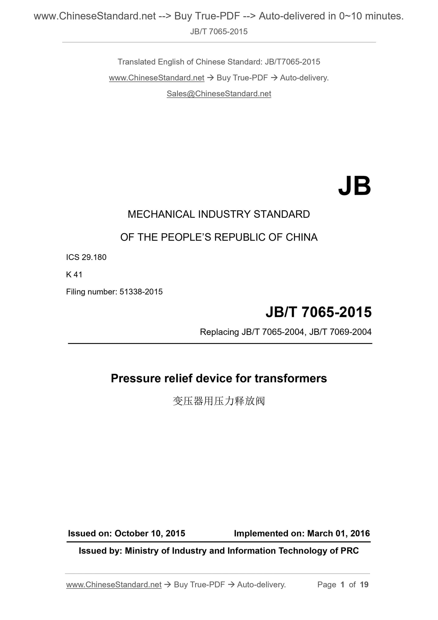
JB/T 7065-2015
JB
MECHANICAL INDUSTRY STANDARD
OF THE PEOPLE’S REPUBLIC OF CHINA
ICS 29.180
K 41
Filing number: 51338-2015
Replacing JB/T 7065-2004, JB/T 7069-2004
Pressure relief device for transformers
ISSUED ON: OCTOBER 10, 2015
IMPLEMENTED ON: MARCH 01, 2016
Issued by: Ministry of Industry and Information Technology of PRC
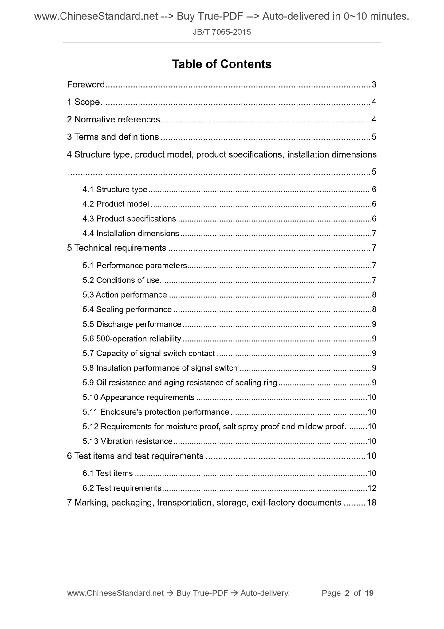
Table of Contents
Foreword ... 3 
1 Scope ... 4 
2 Normative references ... 4 
3 Terms and definitions ... 5 
4 Structure type, product model, product specifications, installation dimensions
... 5 
4.1 Structure type ... 6 
4.2 Product model ... 6 
4.3 Product specifications ... 6 
4.4 Installation dimensions ... 7 
5 Technical requirements ... 7 
5.1 Performance parameters... 7 
5.2 Conditions of use... 7 
5.3 Action performance ... 8 
5.4 Sealing performance ... 8 
5.5 Discharge performance ... 9 
5.6 500-operation reliability ... 9 
5.7 Capacity of signal switch contact ... 9 
5.8 Insulation performance of signal switch ... 9 
5.9 Oil resistance and aging resistance of sealing ring ... 9 
5.10 Appearance requirements ... 10 
5.11 Enclosure’s protection performance ... 10 
5.12 Requirements for moisture proof, salt spray proof and mildew proof ... 10 
5.13 Vibration resistance ... 10 
6 Test items and test requirements ... 10 
6.1 Test items ... 10 
6.2 Test requirements ... 12 
7 Marking, packaging, transportation, storage, exit-factory documents ... 18 
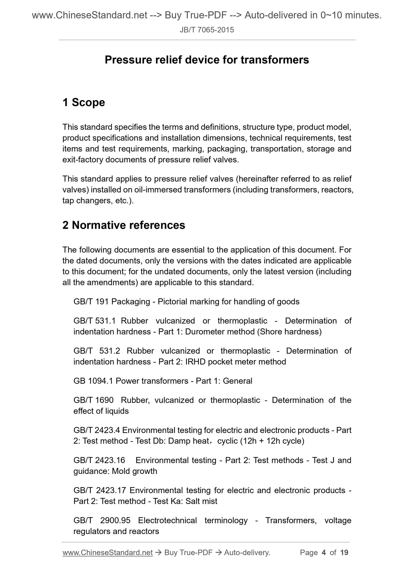
Pressure relief device for transformers
1 Scope
This standard specifies the terms and definitions, structure type, product model,
product specifications and installation dimensions, technical requirements, test
items and test requirements, marking, packaging, transportation, storage and
exit-factory documents of pressure relief valves.
This standard applies to pressure relief valves (hereinafter referred to as relief
valves) installed on oil-immersed transformers (including transformers, reactors,
tap changers, etc.).
2 Normative references
The following documents are essential to the application of this document. For
the dated documents, only the versions with the dates indicated are applicable
to this document; for the undated documents, only the latest version (including
all the amendments) are applicable to this standard.
GB/T 191 Packaging - Pictorial marking for handling of goods
GB/T 531.1 Rubber vulcanized or thermoplastic - Determination of
indentation hardness - Part 1: Durometer method (Shore hardness)
GB/T 531.2 Rubber vulcanized or thermoplastic - Determination of
indentation hardness - Part 2: IRHD pocket meter method
GB 1094.1 Power transformers - Part 1: General
GB/T 1690 Rubber, vulcanized or thermoplastic - Determination of the
effect of liquids
GB/T 2423.4 Environmental testing for electric and electronic products - Part
2: Test method - Test Db: Damp heat, cyclic (12h + 12h cycle)
GB/T 2423.16 Environmental testing - Part 2: Test methods - Test J and
guidance: Mold growth
GB/T 2423.17 Environmental testing for electric and electronic products -
Part 2: Test method - Test Ka: Salt mist
GB/T 2900.95 Electrotechnical terminology - Transformers, voltage
regulators and reactors
GB 4208 Degrees of protection provided by enclosure (IP Code)
JB/T 3837 Identification method of transformers product type
JB/T 8448.1 Technical specifications of sealing articles for transformer and
similar products - Part 1: Rubber sealing articles
JB/T 8448.2 Technical specifications of sealing articles for transformer and
similar products - Part 2: Cork rubber sealing articles
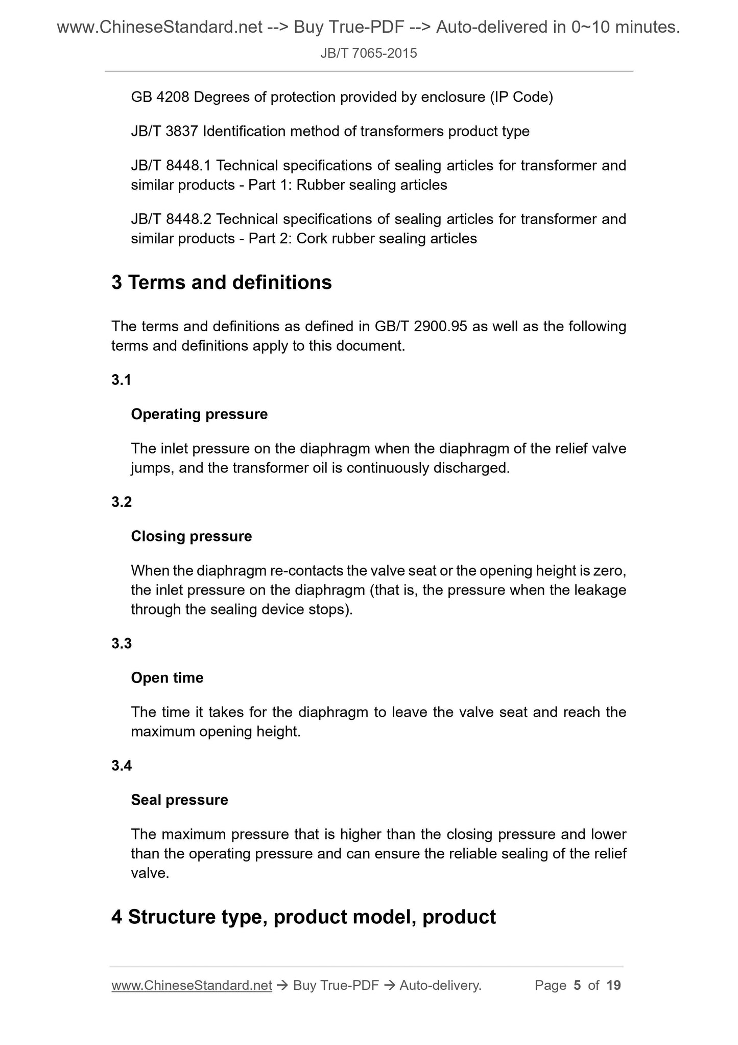
3 Terms and definitions
The terms and definitions as defined in GB/T 2900.95 as well as the following
terms and definitions apply to this document.
3.1
Operating pressure
The inlet pressure on the diaphragm when the diaphragm of the relief valve
jumps, and the transformer oil is continuously discharged.
3.2
Closing pressure
When the diaphragm re-contacts the valve seat or the opening height is zero,
the inlet pressure on the diaphragm (that is, the pressure when the leakage
through the sealing device stops).
3.3
Open time
The time it takes for the diaphragm to leave the valve seat and reach the
maximum opening height.
3.4
Seal pressure
The maximum pressure that is higher than the closing pressure and lower
than the operating pressure and can ensure the reliable sealing of the relief
valve.
4 Structure type, product model, product
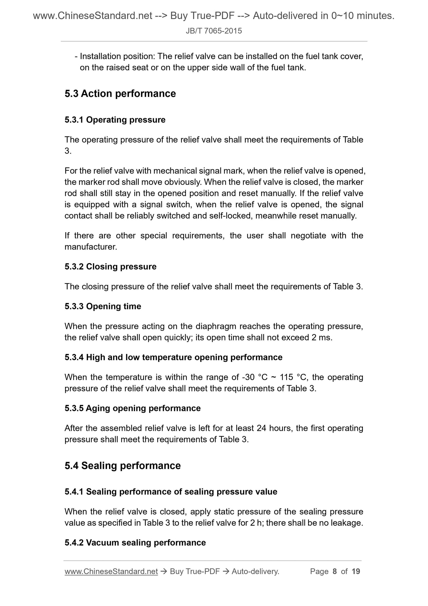
- Installation position: The relief valve can be installed on the fuel tank cover,
on the raised seat or on the upper side wall of the fuel tank.
5.3 Action performance
5.3.1 Operating pressure
The operating pressure of the relief valve shall meet the requirements of Table
3.
For the relief valve with mechanical signal mark, when the relief valve is opened,
the marker rod shall move obviously. When the relief valve is closed, the marker
rod shall still stay in the opened position and reset manually. If the relief valve
is equipped with a signal switch, when the relief valve is opened, the signal
contact shall be reliably switched and self-locked, meanwhile reset manually.
If there are other special requirements, the user shall negotiate with the
manufacturer.
5.3.2 Closing pressure
The closing pressure of the relief valve shall meet the requirements of Table 3.
5.3.3 Opening time
When the pressure acting on the diaphragm reaches the operating pressure,
the relief valve shall open quickly; its open time shall not exceed 2 ms.
5.3.4 High and low temperature opening performance
When the temperature is within the range of -30 °C ~ 115 °C, the operating
pressure of the relief valve shall meet the requirements of Table 3.
5.3.5 Aging opening performance
After the assembled relief valve is left for at least 24 hours, the first operating
pressure shall meet the requirements of Table 3.
5.4 Sealing performance
5.4.1 Sealing performance of sealing pressure value
When the relief valve is closed, apply static pressure of the sealing pressure
value as specified in Table 3 to the relief valve for 2 h; there shall be no leakage.
5.4.2 Vacuum sealing performance
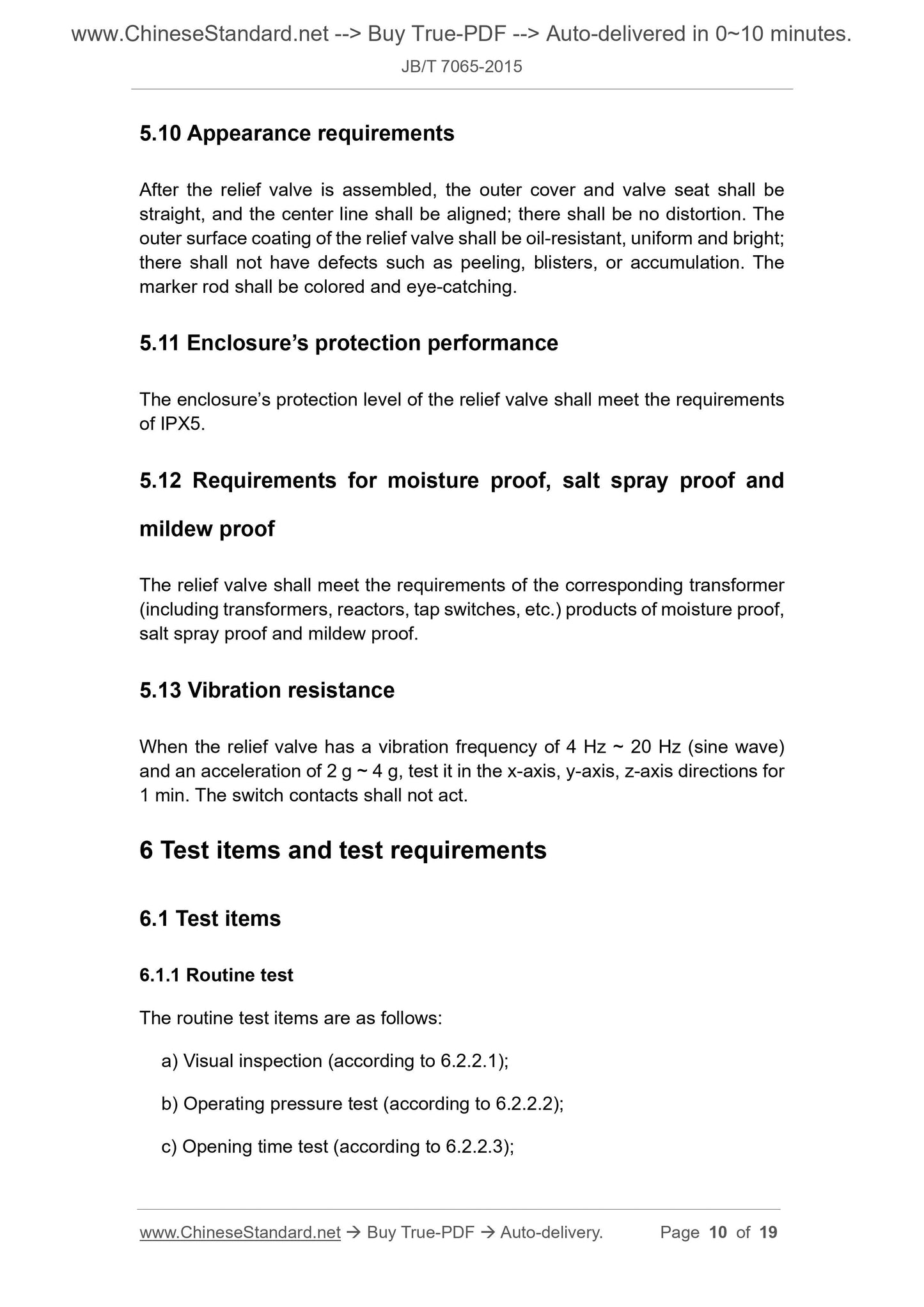
5.10 Appearance requirements
After the relief valve is assembled, the outer cover and valve seat shall be
straight, and the center line shall be aligned; there shall be no distortion. The
outer surface coating of the relief valve shall be oil-resistant, uniform and bright;
there shall not have defects such as peeling, blisters, or accumulation. The
marker rod shall be colored and eye-catching.
5.11 Enclosure’s protection performance
The enclosure’s protection level of the relief valve shall meet the requirements
of IPX5.
5.12 Requirements for moisture proof, salt spray proof and
mildew proof
The relief valve shall meet the requirements of the corresponding transformer
(including transformers, reactors, tap switches, etc.) products of moisture proof,
salt spray proof and mildew proof.
5.13 Vibration resistance
When the relief valve has a vibration frequency of 4 Hz ~ 20 Hz (sine wave)
and an acceleration of 2 g ~ 4 g, test it in the x-axis, y-axis, z-axis directions for
1 min. The switch contacts shall not act.
6 Test items and test requirements
6.1 Test items
6.1.1 Routine test
The routine test items are as follows:
a) Visual inspection (according to 6.2.2.1);
b) Operating pressure test (according to 6.2.2.2);
c) Opening time test (according to 6.2.2.3);
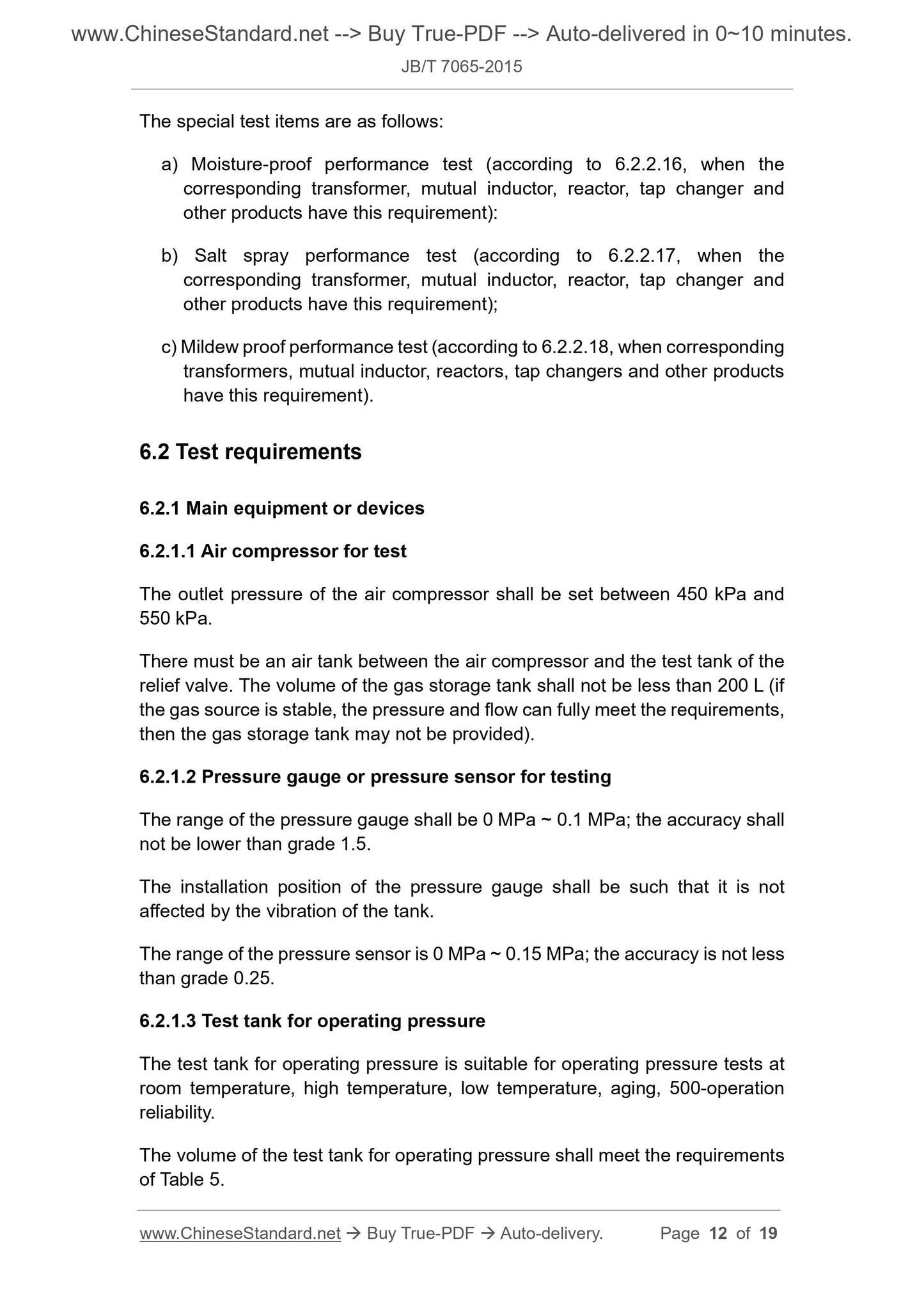
The special test items are as follows:
a) Moisture-proof performance test (according to 6.2.2.16, when the
corresponding transformer, mutual inductor, reactor, tap changer and
other products have this requirement):
b) Salt spray performance test (according to 6.2.2.17, when the
corresponding transformer, mutual inductor, reactor, tap changer and
other products have this requirement);
c) Mildew proof performance test (according to 6.2.2.18, when corresponding
transformers, mutual inductor, reactors, tap changers and other products
have this requirement).
6.2 Test requirements
6.2.1 Main equipment or devices
6.2.1.1 Air compressor for test
The outlet pressure of the air compressor shall be set between 450 kPa and
550 kPa.
There must be an air tank between the air compressor and the test tank of the
relief valve. The volume of the gas storage tank shall not be less than 200 L (if
the gas source is stable, the pressure and flow can fully meet the requirements,
then the gas storage tank may not be provided).
6.2.1.2 Pressure gauge or pressure sensor for testing
The range of the pressure gauge shall be 0 MPa ~ 0.1 MPa; the accuracy shall
not be lower than grade 1.5.
The installation position of the pressure gauge shall be such that it is not
affected by the vibration of the tank.
The range of the pressure sensor is 0 MPa ~ 0.15 MPa; the accuracy is not less
than grade 0.25.
6.2.1.3 Test tank for operating pressure
The test tank for operating pressure is suitable for operating pressure tests at
room temperature, high temperature, low temperature, aging, 500-operation
reliability.
The volume of the test tank for operating pressure shall meet the requirements
of Table 5.
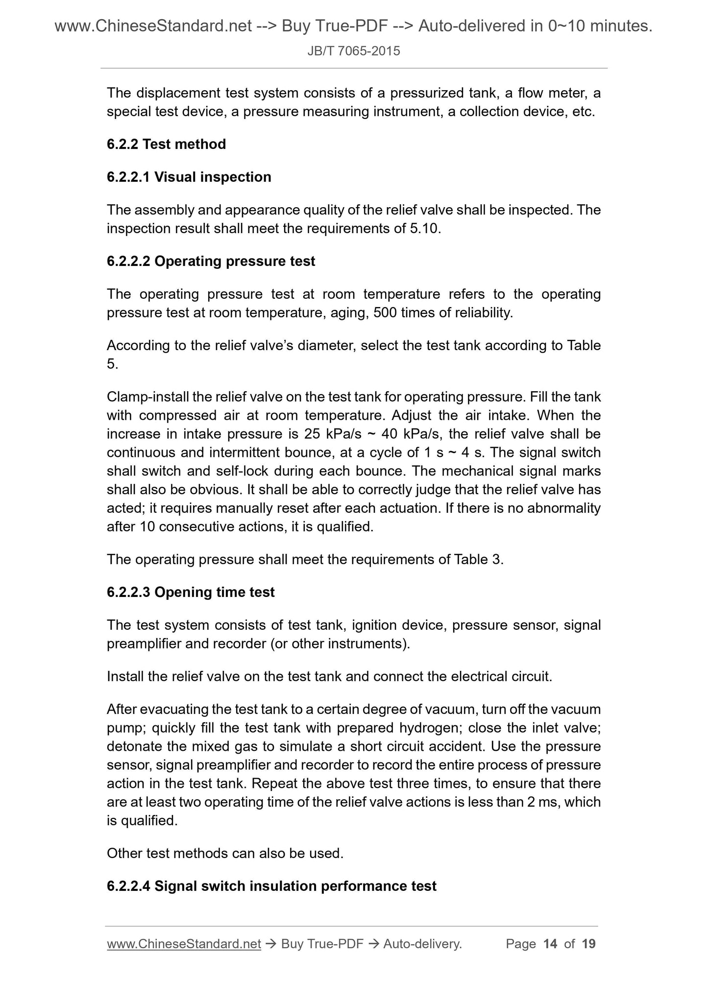
The displacement test system consists of a pressurized tank, a flow meter, a
special test device, a pressure measuring instrument, a collection device, etc.
6.2.2 Test method
6.2.2.1 Visual inspection
The assembly and appearance quality of the relief valve shall be inspected. The
inspection result shall meet the requirements of 5.10.
6.2.2.2 Operating pressure test
The operating pressure test at room temperature refers to the operating
pressure test at room temperature, aging, 500 times of reliability.
According to the relief valve’s diameter, select the test tank according to Table
5.
Clamp-install the relief valve on the test tank for operating pressure. Fill the tank
with compressed air at room temperature. Adjust the air intake. When the
increase in intake pressure is 25 kPa/s ~ 40 kPa/s, the relief valve shall be
continuous and intermittent bounce, at a cycle of 1 s ~ 4 s. The signal switch
shall switch and self-lock during each bounce. The mechanical signal marks
shall also be obvious. It shall be able to correctly judge that the relief valve has
acted; it requires manually reset after each actuation. If there is no abnormality
after 10 consecutive actions, it is qualified.
The operating pressure shall meet the requirements of Table 3.
6.2.2.3 Opening time test
The test system consists of test tank, ignition device, pressure sensor, signal
preamplifier and recorder (or other instruments).
Install the relief valve on the test tank and connect the electrical circuit.
After evacuating the test tank to a certain degree of vacuum, turn off the vacuum
pump; quickly fill the test tank with prepared hydrogen; close the inlet valve;
detonate the mixed gas to simulate a short circuit accident. Use the pressure
sensor, signal preamplifier and recorder to record the entire process of pressure
action in the test tank. Repeat the above test three times, to ensure that there
are at least two operating time of the relief valve actions is less than 2 ms, which
is qualified.
Other test methods can also be used.
6.2.2.4 Signal switch insulation performance test
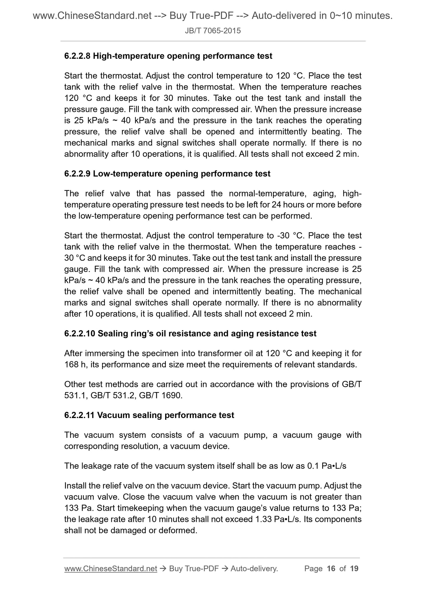
6.2.2.8 High-temperature opening performance test
Start the thermostat. Adjust the control temperature to 120 °C. Place the test
tank with the relief valve in the thermostat. When the temperature reaches
120 °C and keeps it for 30 minutes. Take out the test tank and install the
pressure gauge. Fill the tank with compressed air. When the pressure increase
is 25 kPa/s ~ 40 kPa/s and the pressure in the tank reaches the operating
pressure, the relief valve shall be opened and intermittently beating. The
mechanical marks and signal switches shall operate normally. If there is no
abnormality after 10 operations, it is qualified. All tests shall not exceed 2 min.
6.2.2.9 Low-temperature opening performance test
The relief valve that has passed the normal-temperature, aging, high-
temperature operating pressure test needs to be left for 24 hours or more before
the low-temperature opening performance test can be performed.
Start the thermostat. Adjust the control temperature to -30 °C. Place the test
tank with the relief valve in the thermostat. When the temperature reaches -
30 °C and keeps it for 30 minutes. Take out the test tank and install the pressure
gauge. Fill the tank with compressed air. When the pressure increase is 25
kPa/s ~ 40 kPa/s and the pressure in the tank reaches the operating pressure,
the relief valve shall be opened and intermittently beating. The mechanical
marks and signal switches shall operate normally. If there is no abnormality
after 10 operations, it is qualified. All tests shall not exceed 2 min.
6.2.2.10 Sealing ring’s oil resistance and aging resistance test
After immersing the specimen into transformer oil at 120 °C and keeping it for
168 h, its performance and size meet the requirements of relevant standards.
Other test methods are carried out in accordance with the provisions of GB/T
531.1, GB/T 531.2, GB/T 1690.
6.2.2.11 Vacuum sealing performance test
The vacuum system consists of a vacuum pump, a vacuum gauge with
corresponding resolution, a vacuum device.
The leakage rate of the vacuum system itself shall be as low as 0.1 Pa•L/s
Install the relief valve on the vacuum device. Start the vacuum pump. Adjust the
vacuum valve. Close the vacuum valve when the vacuum is not greater than
133 Pa. Start timekeeping when the vacuum gauge’s value returns to 133 Pa;
the leakage rate after 10 minutes shall not exceed 1.33 Pa•L/s. Its components
shall not be damaged or deformed.
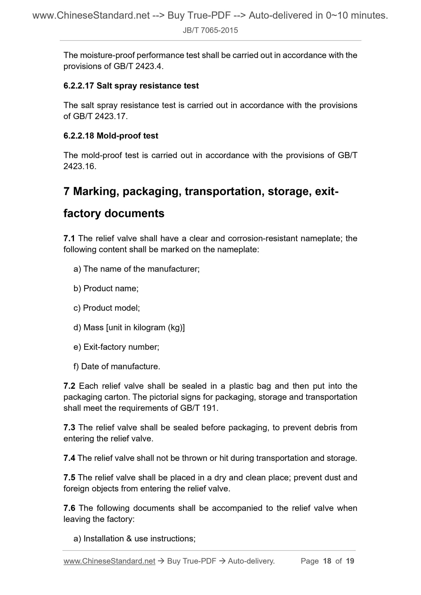
The moisture-proof performance test shall be carried out in accordance with the
provisions of GB/T 2423.4.
6.2.2.17 Salt spray resistance test
The salt spray resistance test is carried out in accordance ...
View full details