JB/T 6105-2007 English PDF (JBT6105-2007)
Regular price
$70.00 USD
Regular price
Sale price
$70.00 USD
Unit price
/
per
Delivery: 3 seconds. Download true-PDF + Invoice.
Get QUOTATION in 1-minute: Click JB/T 6105-2007
Historical versions: JB/T 6105-2007
Preview True-PDF (Reload/Scroll if blank)
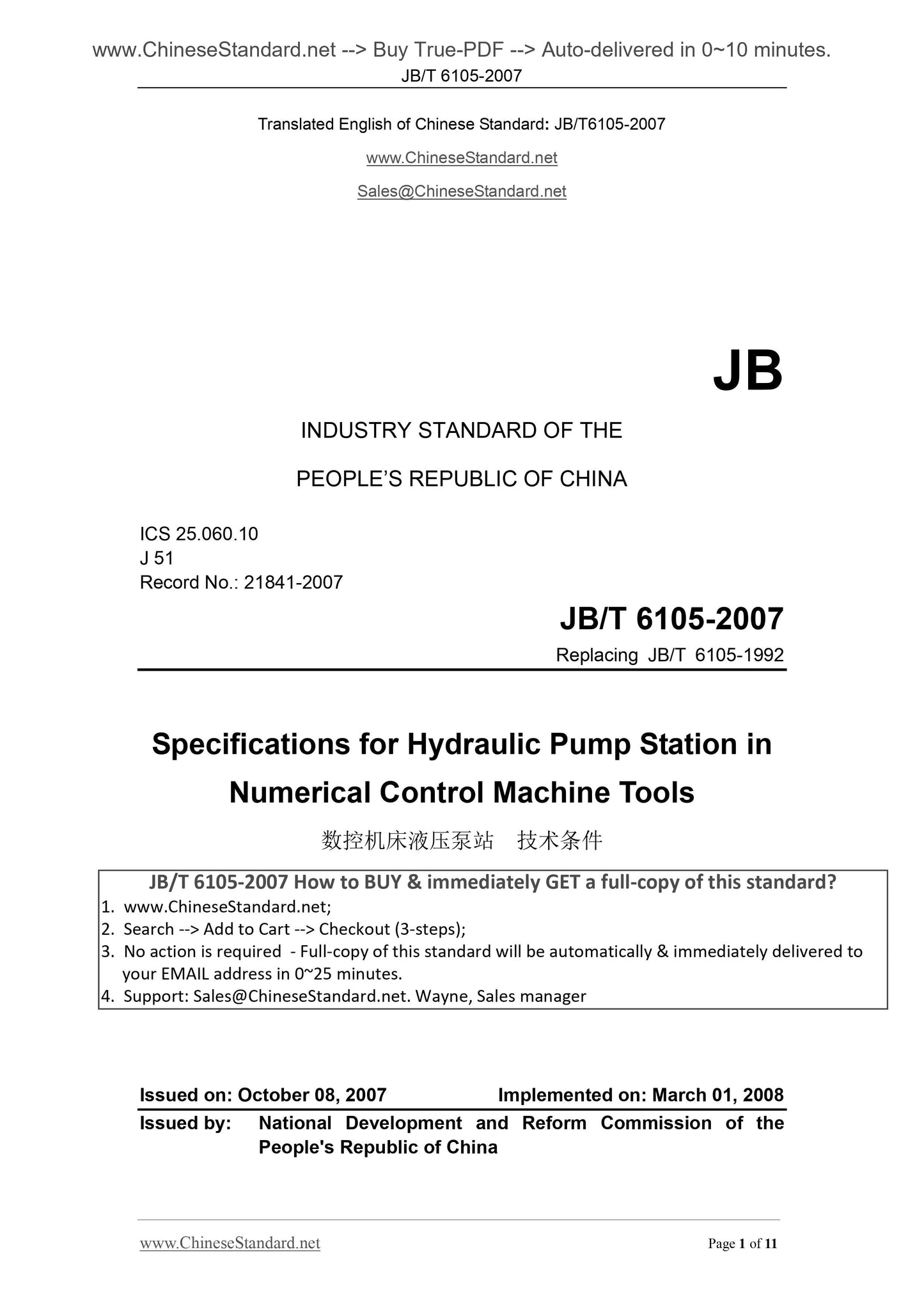
JB/T 6105-2007: Specifications for Hydraulic Pump Station in Numerical Control Machine Tools
JB/T 6105-2007
JB
INDUSTRY STANDARD OF THE
PEOPLE’S REPUBLIC OF CHINA
ICS 25.060.10
J 51
Record No.. 21841-2007
Replacing JB/T 6105-1992
Specifications for Hydraulic Pump Station in
Numerical Control Machine Tools
ISSUED ON. OCTOBER 08, 2007
IMPLEMENTED ON. MARCH 01, 2008
Issued by. National Development and Reform Commission of the
People's Republic of China
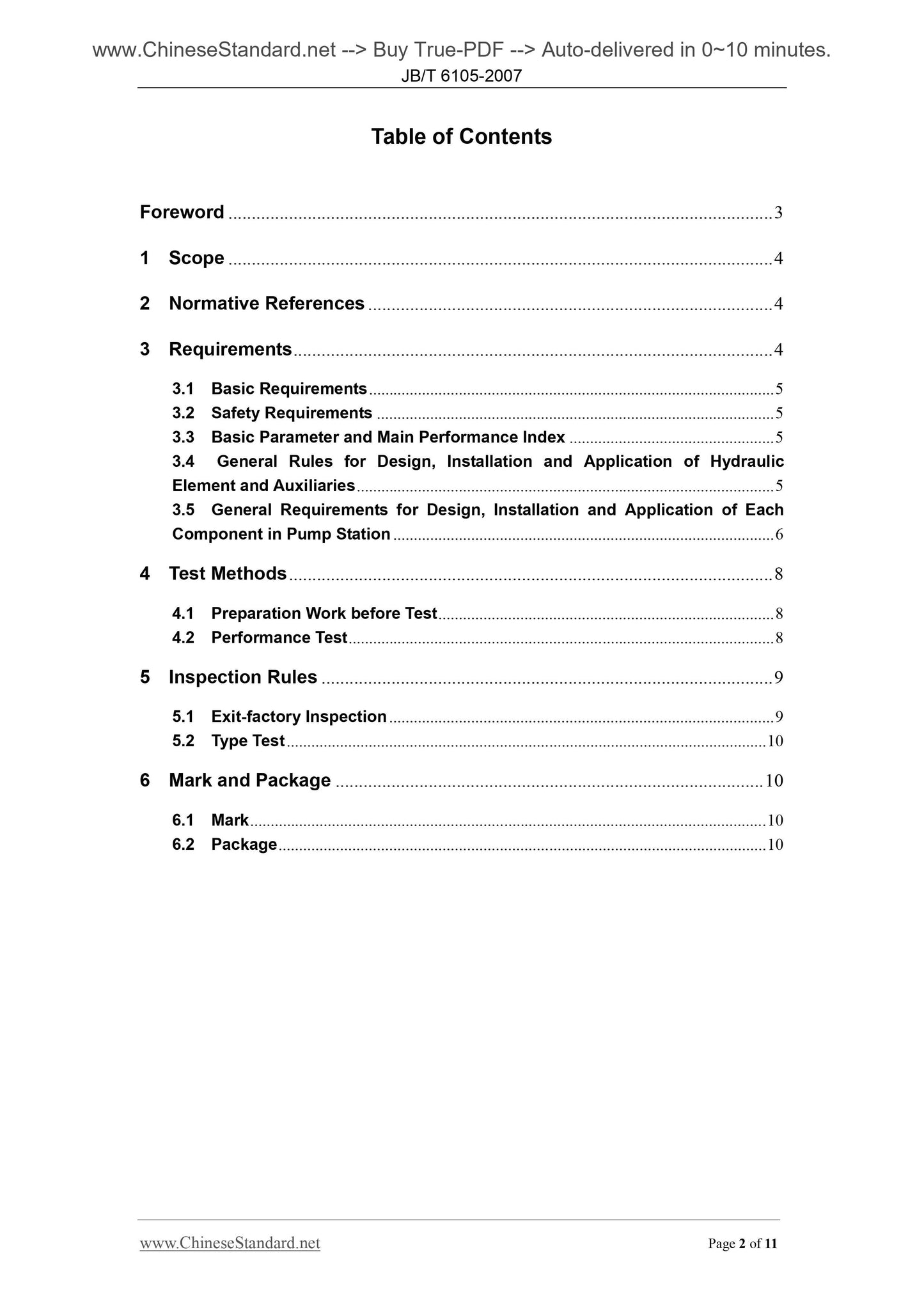
Table of Contents
Foreword ... 3
1 Scope ... 4
2 Normative References ... 4
3 Requirements ... 4
3.1 Basic Requirements ... 5
3.2 Safety Requirements ... 5
3.3 Basic Parameter and Main Performance Index ... 5
3.4 General Rules for Design, Installation and Application of Hydraulic
Element and Auxiliaries ... 5
3.5 General Requirements for Design, Installation and Application of Each
Component in Pump Station ... 6
4 Test Methods ... 8
4.1 Preparation Work before Test ... 8
4.2 Performance Test ... 8
5 Inspection Rules ... 9
5.1 Exit-factory Inspection ... 9
5.2 Type Test ... 10
6 Mark and Package ... 10
6.1 Mark ... 10
6.2 Package ... 10
Foreword
This Standard replaces JB/T 6105-1992 "Specifications for Hydraulic Pump Station in
Numerical Control Machine Tools".
Compared with JB/T 6105-1992, the main changes of this Standard are as follows.
— All normative references in this Standard are changed into the current version;
— Some technical content is modified.
This Standard was proposed by China Machinery Industry Federation.
This Standard shall be under the jurisdiction of National Technical Committee on
Metal Cutting Machine Tools of Standardization Administration of China (SAC/TC 22).
Drafting organizations of this Standard. Guangzhou Mechanical Engineering
Research Institute, and Guangzhou Baolite Hydraulic Seal Ltd.
Chief drafting staffs of this Standard. Chen Tiansheng, Lin Benhong, Li Baoxin, and
Guo Hongdi.
The previous version replaced by this Standard is.
— JB/T 6105-1992.
Specifications for Hydraulic Pump Station in
Numerical Control Machine Tools
1 Scope
This Standard specifies the basic parameters, main performance indexes, and
general requirements of design, manufacture, installation and application (including
the relevant components) for the hydraulic pump station in numerical control machine
tools (hereinafter referred to as "pump station").
This Standard is applicable to the pump station that uses the hydraulic oil as the
working medium.
2 Normative References
The following standards contain provisions which, through reference in this text,
constitute provisions of this Standard. For dated reference, the subsequent
modifications (excluding corrigendum) or revisions of these publications do not apply.
However, all parties who enter into an agreement according to this Standard are
encouraged to study whether the latest edition of these documents is applicable. For
undated normative references, the latest edition is applicable to this Standard.
GB/T 191 "Packaging - Pictorial Marking for Handling of Goods" (GB/T 191-2000,
eqv ISO780.1997)
GB/T 3766 "Hydraulic Fluid Power - General Rules Relating to Systems" (GB/
T3766-2001, eqv ISO 4413.1998)
GB/T 7632 "Recommendations for the Choice of Lubricants for Machine Tools"
(GB/T 7632-1987, neq BS 5063.1982)
GB/T 7935 "Hydraulic Fluid Power - General Requirements for Hydraulic
Components"
GB/T 14039 "Hydraulic Fluid Power – Fluids - Method for Coding the Level of
Contamination by Solid Particles"(GB/T 14039-2002, ISO 4406.1999, MOD)
JB/T 7938 "Hydraulic Fluid Power - Power Units - Nominal Capacities of Reservoir"
JB/T 8356.1 "Specification for Machine Tool Package"
3 Requirements
3.5.3.1 The cooling or heating measures may be adopted according to the
performance requirements and operating conditions of the hydraulic equipment; for
the system with special requirements, the constant temperature oil tank may be
adopted to maintain the normal working temperature of the fluid.
3.5.3.2 When the immersion cooler or heater is adopted in the oil tank, the
installation shall make it maintain the immersion state at the lowest oil level.
3.5.4 Oil filter component
3.5.4.1 For the oil filter on the intake pipe of the hydraulic pump, the oil passing
capacity shall be larger than twice of pump capacity. For the fine filter on the pipeline,
the filtering fineness must ensure the cleanliness level requirements of the fluid, and
the installation of the fine filter shall be convenient for dismantling.
3.5.4.2 The filter element of the oil filter shall be periodically replaced, and the
pollution indication or alarm device shall be equipped.
3.5.5 Accumulator component
3.5.5.1 The parameters such as oil suction, drain flow, and pressure of accumulator
shall be in accordance with the system application requirements.
3.5.5.2 The one-way valve shall be installed between the accumulator and hydraulic
pump to prevent back flow of the pressure oil in the accumulator during pump shut
down.
3.5.5.3 The stop valve shall be installed between the accumulator and system,
which is used for gas filling, inspection and maintenance of the accumulator or long
term shutdown.
3.5.5.4 The accumulator in the oil filling state shall not be dismantled.
3.5.6 Pipe fittings
3.5.6.1 The oil suction port of the pump shall keep the distance as far as possible
from oil return port and oil drain port of the system; all pipes shall be inserted below
the lowest oil level.
3.5.6.2 The distance H from the oil suction pipe and the tank bottom shall be larger
than 2D (D is the pipe diameter); the distance from the tank wall shall be larger than
3D; the distance H from the oil return pipe and oil drain pipe shall be larger than 3D,
and the pipe orifice shall face the tank wall.
3.5.6.3 When the oil return tank of the same pipe is adopted for oil drain pipe,
guiding control oil return pipe and main oil return pipe, then the reliable and
interference protection method shall be provided. If not, the pipe oil return tank shall
be equipped separately.
d) Noise test.
5.2 Type Test
5.2.1 The type test shall be carried out under any of the following conditions.
a) The trial manufacture and typing identification when new products or old
products are transferred to another plant;
b) The inspection shall be carried out periodically when mass production;
c) Where the production is resumed after a long-time shutdown.
5.2.2 All type test items shall be carried out according to those specified in Table 2.
5.2.3 The samples of type inspection shall be randomly sampled from the inventory
products; the quantity shall not be less than three sets. If one item is unqualified in the
inspection, the double-quantity re-inspection may be carried out for this item; if it is still
unqualified, this product shall be judged as unqualified.
6 Mark and Package
6.1 Mark
The front of each pump station must be provided with corrosion-proof and
difficult-to-shed nameplate mark; the following contents shall be clearly marked on the
nameplate.
a) Manufacturer name;
b) Product model and name;
c) Main technical parameters. tank capacity, rated pressure and rated discharge;
d) Factory number and manufacture date.
6.2 Package
6.2.1 All inlet and outlet oil ports of the pump station shall be sealed and protected;
the identification mark must be made on the dismantled pipeline and the
corresponding end hole or joint.
6.2.2 The package shall ...