Skip to product information
1 of 10

PayPal, credit cards. Download editable-PDF and invoice in 1 second!

JB/T 5948-1991 English PDF (JBT5948-1991)

JB/T 5948-1991 English PDF (JBT5948-1991)

Regular price $85.00 USD
Regular price Sale price $85.00 USD
Sale Sold out
Shipping calculated at checkout.
Delivery: 3 seconds. Download true-PDF + Invoice.
Get QUOTATION in 1-minute: Click JB/T 5948-1991
Historical versions: JB/T 5948-1991
Preview True-PDF (Reload/Scroll if blank)

JB/T 5948-1991: Construction Machinery caliper disc brakes technical conditions
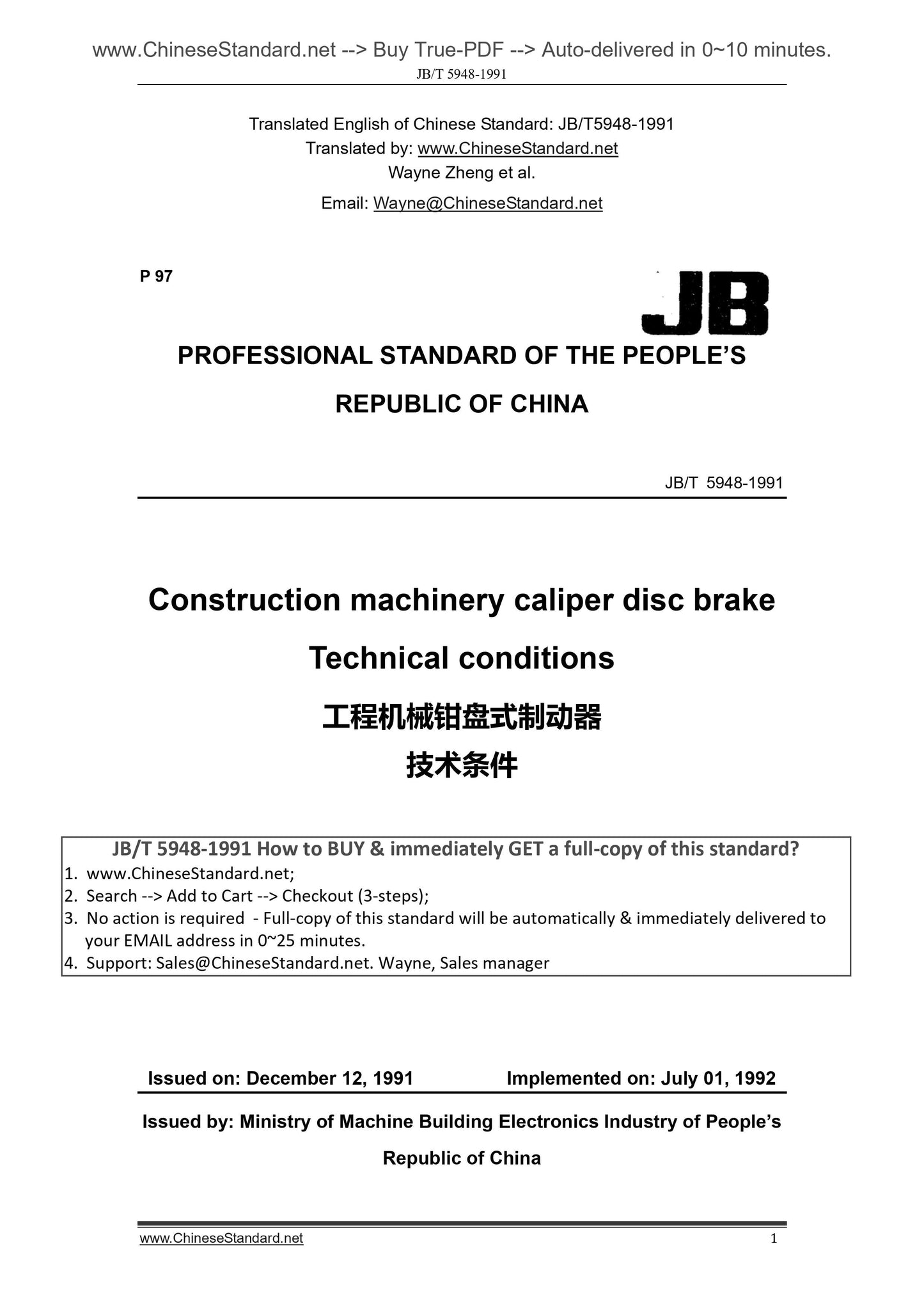
JB/T 5948-1991
P 97
PROFESSIONAL STANDARD OF THE PEOPLE’S
REPUBLIC OF CHINA
Construction machinery caliper disc brake
Technical conditions
ISSUED ON. DECEMBER 12, 1991
IMPLEMENTED ON. JULY 01, 1992
Issued by. Ministry of Machine Building Electronics Industry of People’s
Republic of China
Table of Contents
1 Subject contents and application scope ... 3
2 Normative references ... 3
3 Technical requirements ... 4
4 Test methods ... 8
5 Inspection classifications ... 9
6 Marking, packaging, transportation and storage ... 10
7 Quality assurance periods ... 11
Annex A The technical requirements of main positions of the major
components (Supplement) ... 12
Annex B Calculation method of rotational inertia (Supplement) ... 13
Annex C Records and reports of bench test (Reference) ... 14
Additional explanation ... 15
References and Original Chinese Documents ... 16
PROFESSIONAL STANDARD OF THE PEOPLE’S
REPUBLIC OF CHINA
JB/T 5948-91
Construction machinery caliper disc brake
Technical conditions
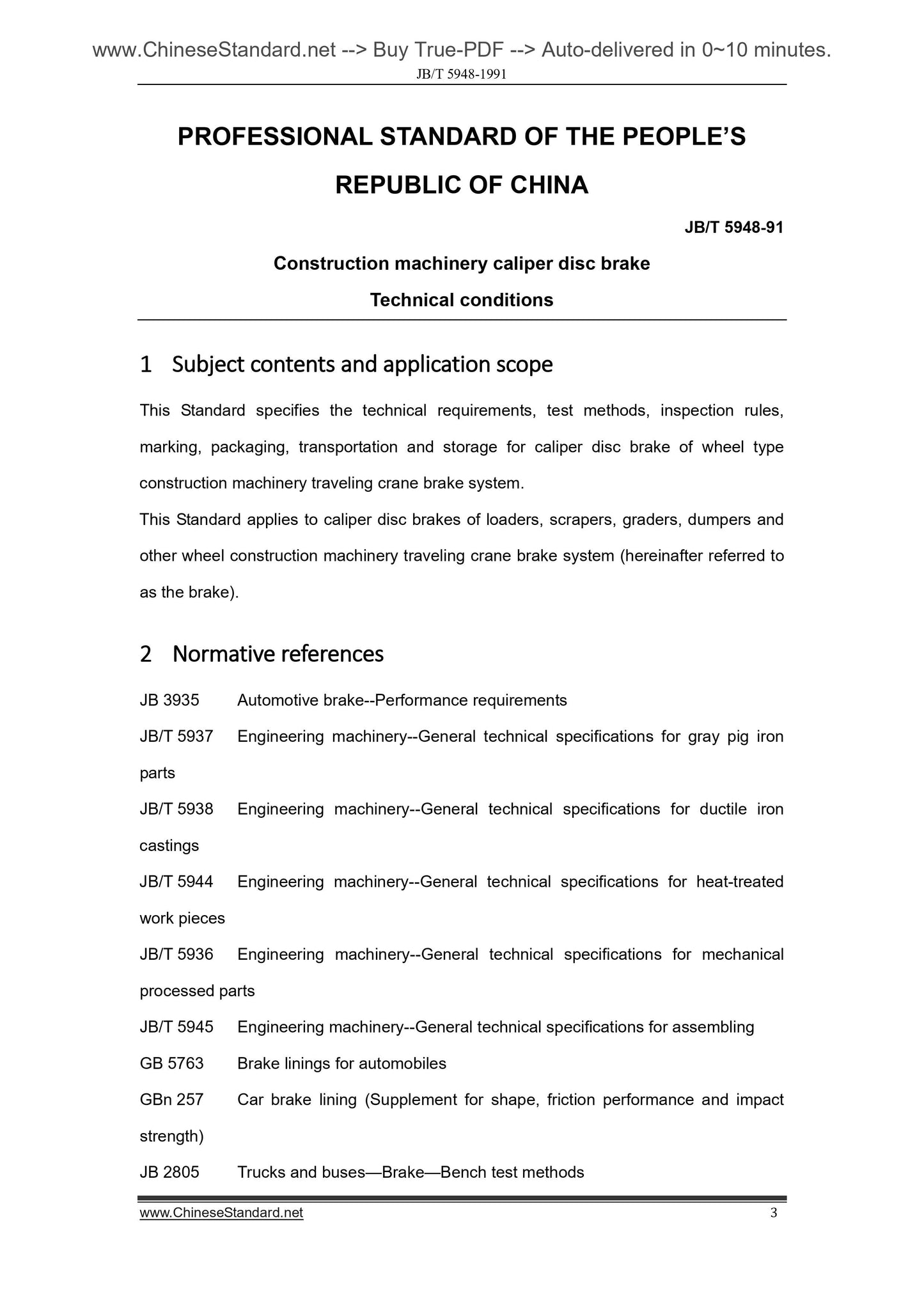
1 Subject contents and application scope
This Standard specifies the technical requirements, test methods, inspection rules,
marking, packaging, transportation and storage for caliper disc brake of wheel type
construction machinery traveling crane brake system.
This Standard applies to caliper disc brakes of loaders, scrapers, graders, dumpers and
other wheel construction machinery traveling crane brake system (hereinafter referred to
as the brake).
2 Normative references
JB 3935 Automotive brake--Performance requirements
JB/T 5937 Engineering machinery--General technical specifications for gray pig iron
parts
JB/T 5938 Engineering machinery--General technical specifications for ductile iron
castings
JB/T 5944 Engineering machinery--General technical specifications for heat-treated
work pieces
JB/T 5936 Engineering machinery--General technical specifications for mechanical
processed parts
JB/T 5945 Engineering machinery--General technical specifications for assembling
GB 5763 Brake linings for automobiles
GBn 257 Car brake lining (Supplement for shape, friction performance and impact
strength)
JB 2805 Trucks and buses—Brake—Bench test methods
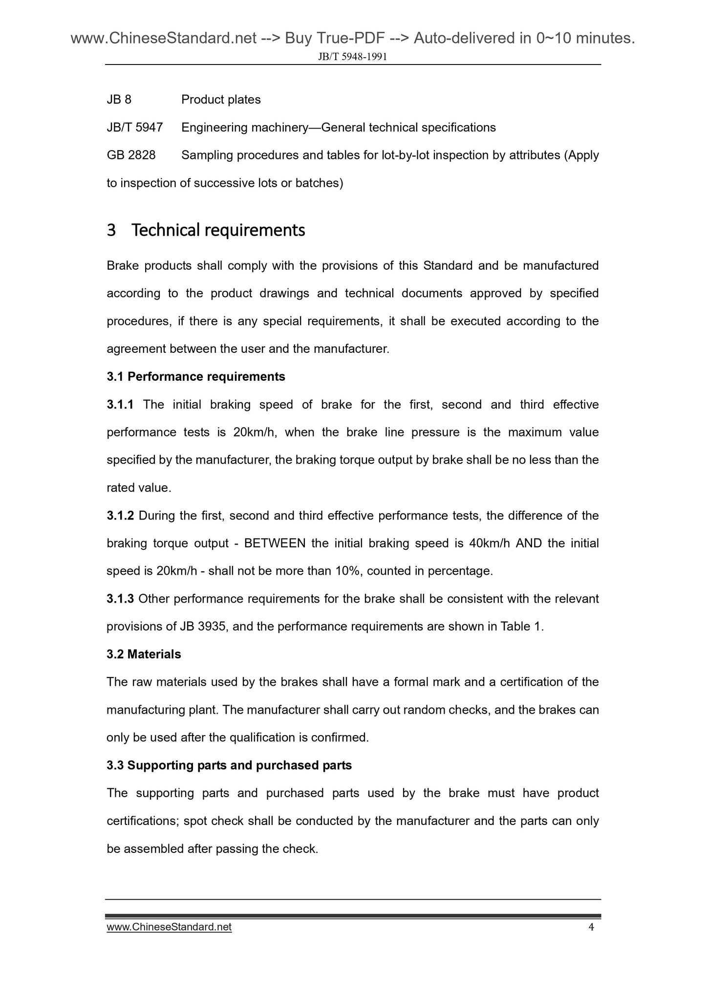
JB 8 Product plates
JB/T 5947 Engineering machinery—General technical specifications
GB 2828 Sampling procedures and tables for lot-by-lot inspection by attributes (Apply
to inspection of successive lots or batches)
3 Technical requirements
Brake products shall comply with the provisions of this Standard and be manufactured
according to the product drawings and technical documents approved by specified
procedures, if there is any special requirements, it shall be executed according to the
agreement between the user and the manufacturer.
3.1 Performance requirements
3.1.1 The initial braking speed of brake for the first, second and third effective
performance tests is 20km/h, when the brake line pressure is the maximum value
specified by the manufacturer, the braking torque output by brake shall be no less than the
rated value.
3.1.2 During the first, second and third effective performance tests, the difference of the
braking torque output - BETWEEN the initial braking speed is 40km/h AND the initial
speed is 20km/h - shall not be more than 10%, counted in percentage.
3.1.3 Other performance requirements for the brake shall be consistent with the relevant
provisions of JB 3935, and the performance requirements are shown in Table 1.
3.2 Materials
The raw materials used by the brakes shall have a formal mark and a certification of the
manufacturing plant. The manufacturer shall carry out random checks, and the brakes can
only be used after the qualification is confirmed.
3.3 Supporting parts and purchased parts
The supporting parts and purchased parts used by the brake must have product
certifications; spot check shall be conducted by the manufacturer and the parts can only
be assembled after passing the check.
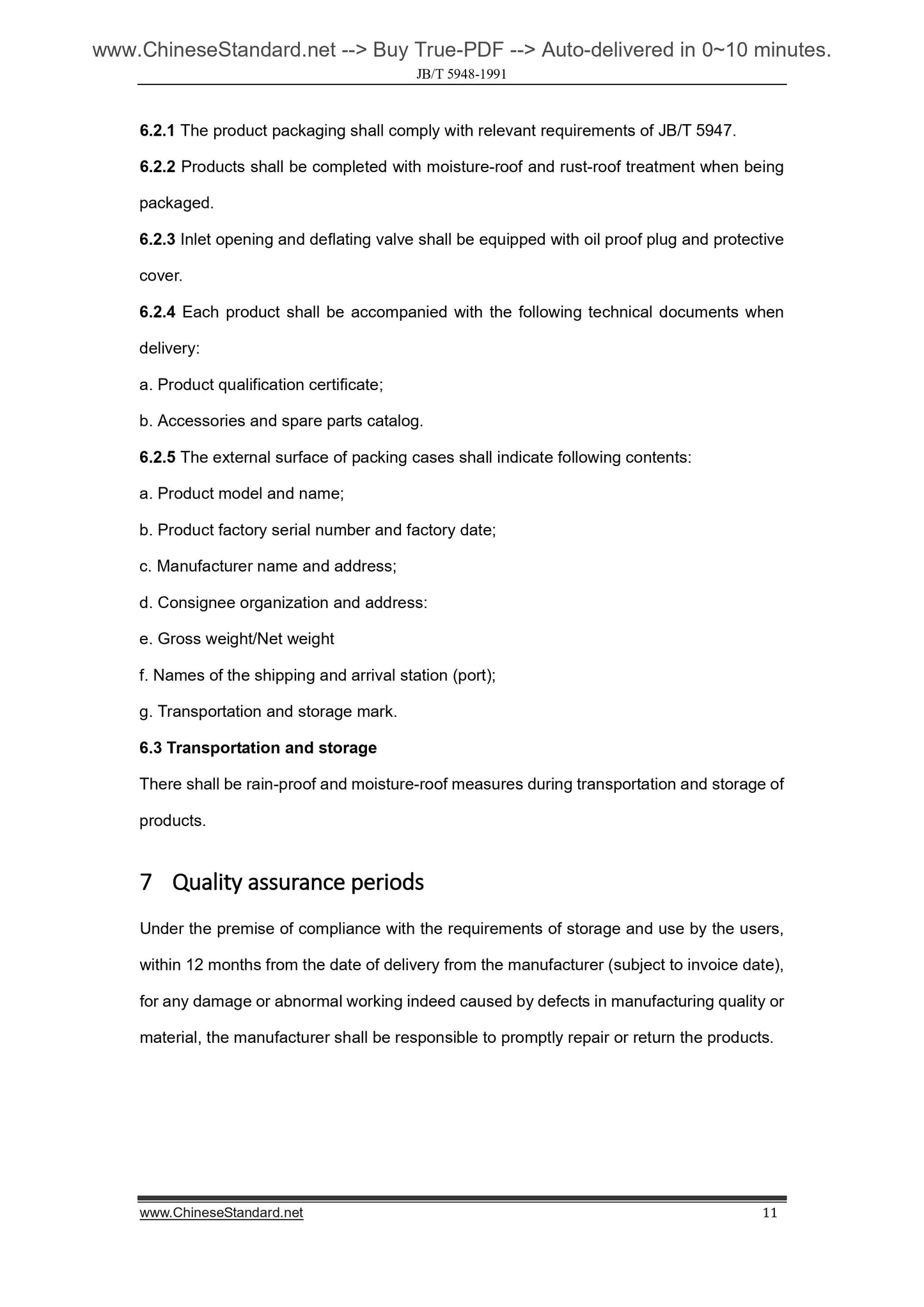
6.2.1 The product packaging shall comply with relevant requirements of JB/T 5947.
6.2.2 Products shall be completed with moisture-roof and rust-roof treatment when being
packaged.
6.2.3 Inlet opening and deflating valve shall be equipped with oil proof plug and protective
cover.
6.2.4 Each product shall be accompanied with the following technical documents when
delivery.
a. Product qualification certificate;
b. Accessories and spare parts catalog.
6.2.5 The external surface of packing cases shall indicate following contents.
a. Product model and name;
b. Product factory serial number and factory date;
c. Manufacturer name and address;
d. Consignee organization and address.
e. Gross weight/Net weight
f. Names of the shipping and arrival station (port);
g. Transportation and storage mark.
6.3 Transportation and storage
There shall be rain-proof and moisture-roof measures during transportation and storage of
products.
7 Quality assurance periods
Under the premise of compliance with the requirements of storage and use by the users,
within 12 months from the date of delivery from the manufacturer (subject to invoice date),
for any damage or abnormal working indeed caused by defects in manufacturing quality or
material, the manufacturer shall be responsible to promptly repair or return the products.
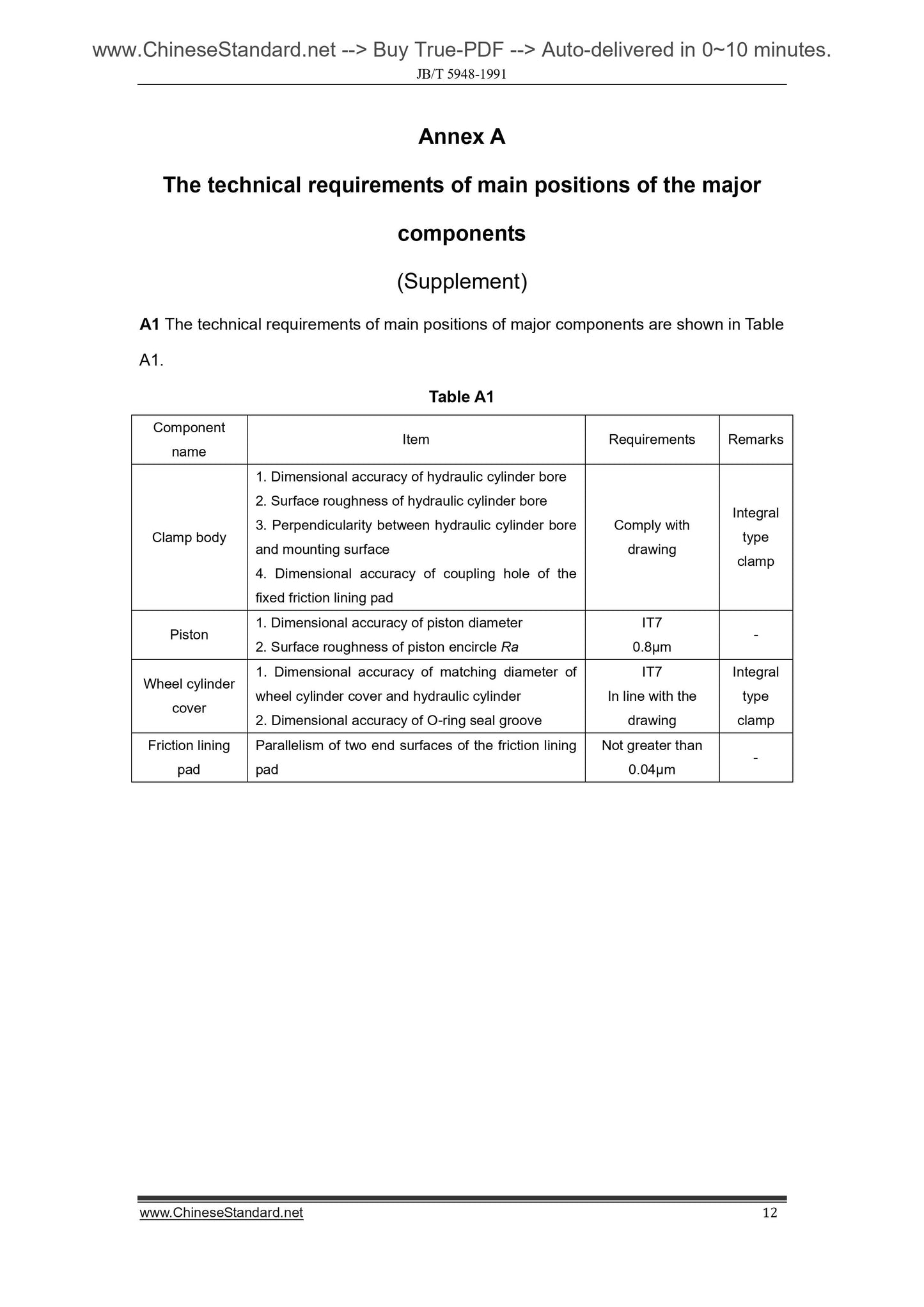
Annex A
The technical requirements of main positions of the major
components
(Supplement)
A1 The technical requirements of main positions of major components are shown in Table
A1.
Table A1
Component
name
Item Requirements Remarks
Clamp body
1. Dimensional accuracy of hydraulic cylinder bore
2. Surface roughness of hydraulic cylinder bore
3. Perpendicularity between hydraulic cylinder bore
and mounting surface
4. Dimensional accuracy of coupling hole of the
fixed friction lining pad
Comply with
drawing
Integral
type
clamp
Piston
1. Dimensional accuracy of piston diameter
2. Surface roughness of piston encircle Ra
IT7
0.8µm
Wheel cylinder
cover
1. Dimensional accuracy of matching diameter of
wheel cylinder cover and hydraulic cylinder
2. Dimensional accuracy of O-ring seal groove
IT7
In line with the
drawing
Integral
type
clamp
Friction lining
pad
Parallelism of two end surfaces of the friction lining
pad
Not greater than
0.04μm
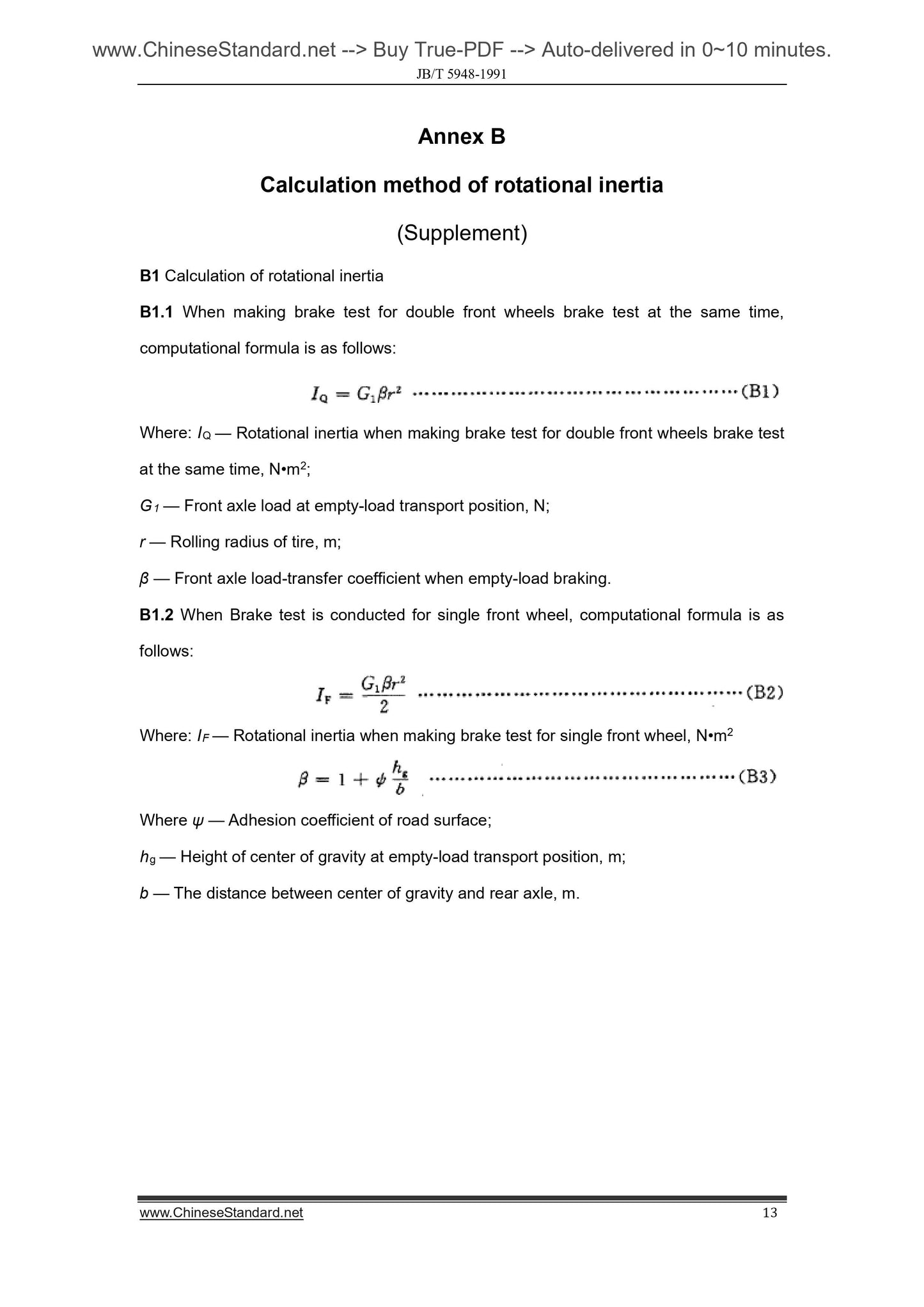
Annex B
Calculation method of rotational inertia
(Supplement)
B1 Calculation of rotational inertia
B1.1 When making brake test for double front wheels brake test at the same time,
computational formula is as follows.
Where. IQ — Rotational inertia when making brake test for double front wheels brake test
at the same time, N•m2;
G1 — Front axle load at empty-load transport position, N;
r — Rolling radius of tire, m;
β — Front axle load-transfer coefficient when empty-load braking.
B1.2 When Brake test is conducted for single front wheel, computational formula is as
follows.
Where. IF — Rotational inertia when making brake test for single front wheel, N•m2
Where ψ — Adhesion coefficient of road surface;
hg — Height of center of gravity at empty-load transport position, m;
b — The distance between center of gravity and rear axle, m.
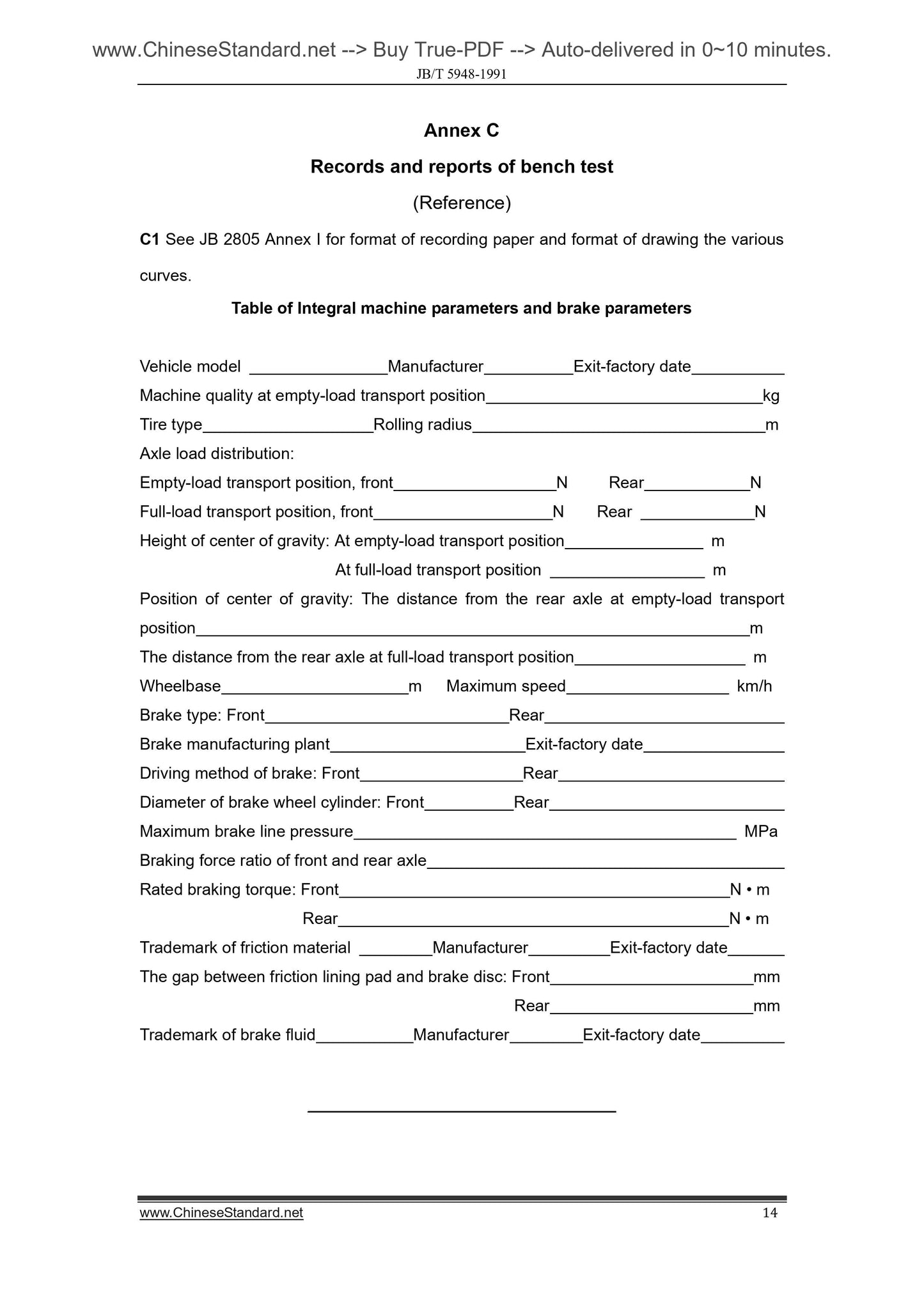
Annex C
Records and reports of bench test
(Reference)
C1 See JB 2805 Annex I for format of recording paper and format of drawing the various
curves.
Table of ...
View full details