JB/T 4330-1999 English PDF (JBT4330-1999)
Regular price
$130.00 USD
Regular price
Sale price
$130.00 USD
Unit price
/
per
Delivery: 3 seconds. Download true-PDF + Invoice.
Get QUOTATION in 1-minute: Click JB/T 4330-1999
Historical versions: JB/T 4330-1999
Preview True-PDF (Reload/Scroll if blank)
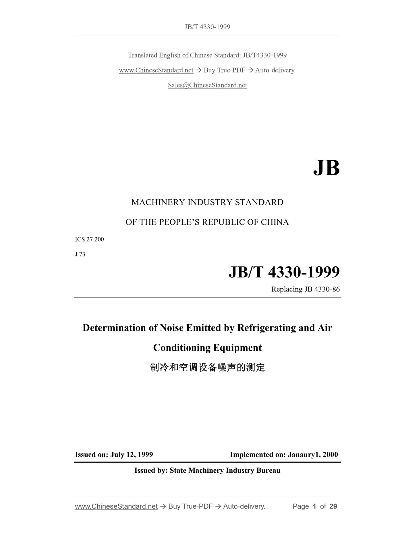
JB/T 4330-1999: Determination of noise emitted by refrigeranting and air conditioning equipments
JB/T 4330-1999
JB
MACHINERY INDUSTRY STANDARD
OF THE PEOPLE’S REPUBLIC OF CHINA
ICS 27.200
J 73
Replacing JB 4330-86
Determination of Noise Emitted by Refrigerating and Air
Conditioning Equipment
ISSUED ON: JULY 12, 1999
IMPLEMENTED ON: JANAURY1, 2000
Issued by: State Machinery Industry Bureau
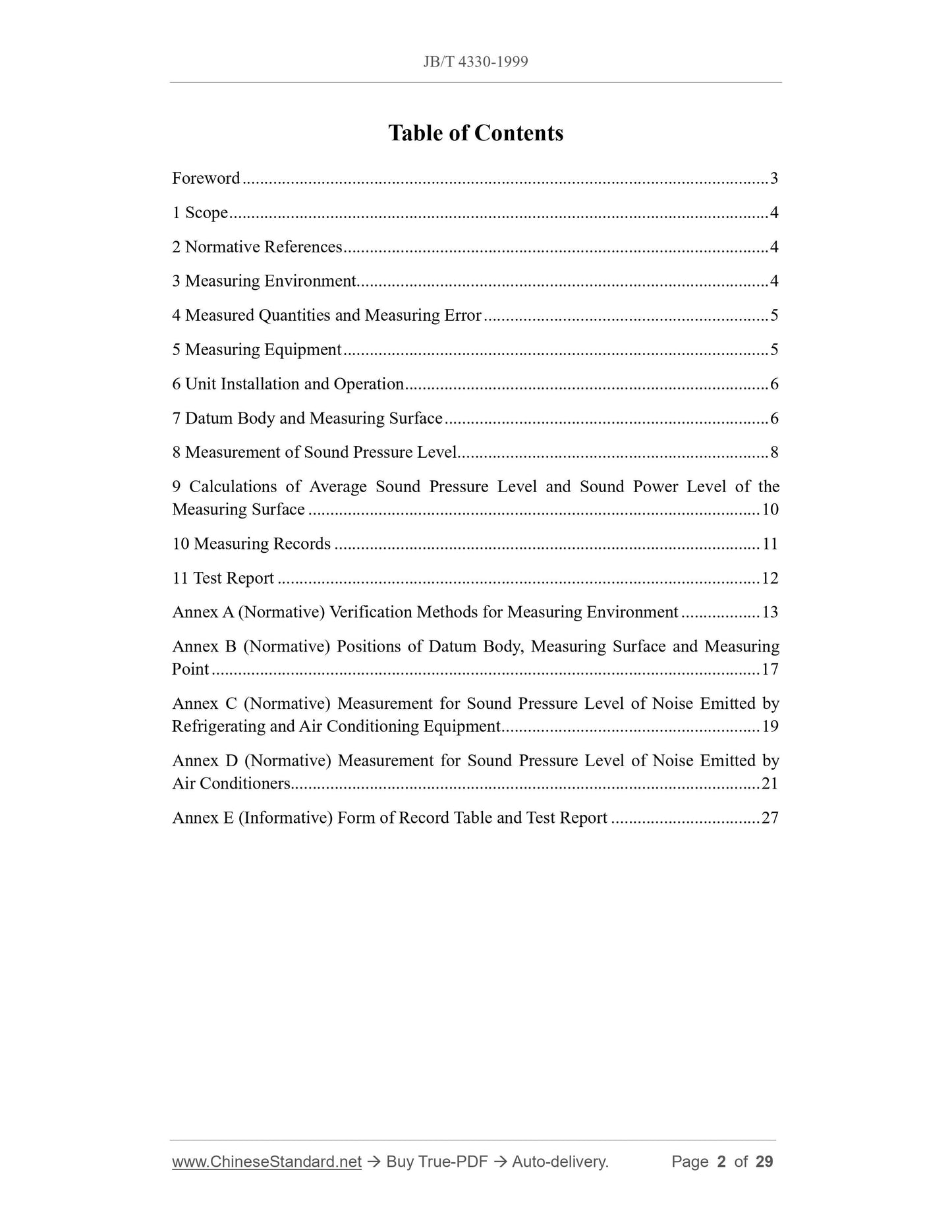
Table of Contents
Foreword ... 3
1 Scope ... 4
2 Normative References ... 4
3 Measuring Environment... 4
4 Measured Quantities and Measuring Error ... 5
5 Measuring Equipment ... 5
6 Unit Installation and Operation ... 6
7 Datum Body and Measuring Surface ... 6
8 Measurement of Sound Pressure Level ... 8
9 Calculations of Average Sound Pressure Level and Sound Power Level of the
Measuring Surface ... 10
10 Measuring Records ... 11
11 Test Report ... 12
Annex A (Normative) Verification Methods for Measuring Environment ... 13
Annex B (Normative) Positions of Datum Body, Measuring Surface and Measuring
Point ... 17
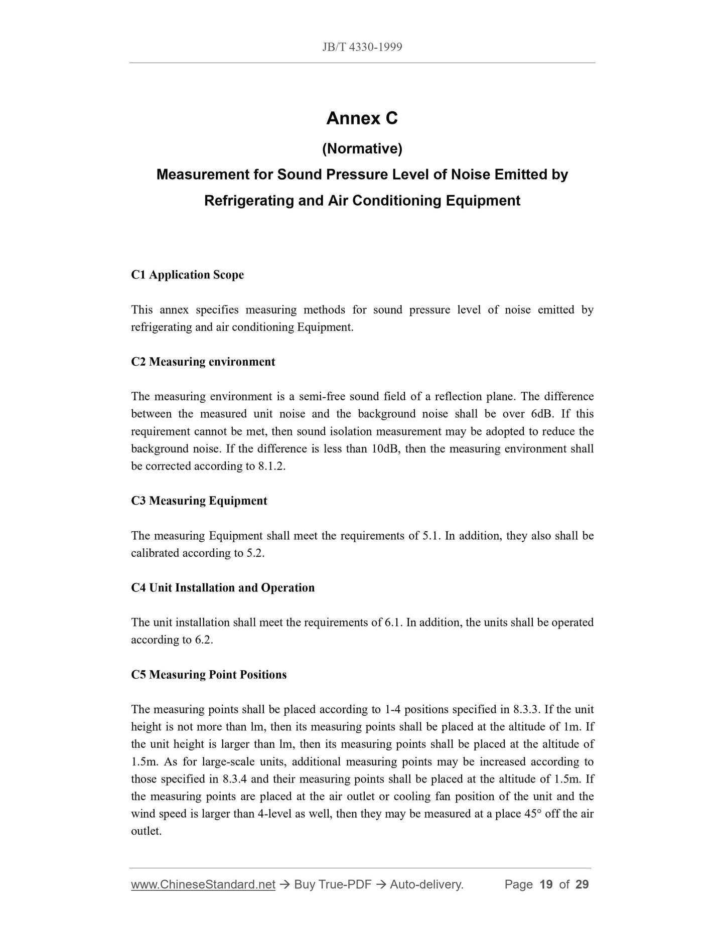
Annex C (Normative) Measurement for Sound Pressure Level of Noise Emitted by
Refrigerating and Air Conditioning Equipment ... 19
Annex D (Normative) Measurement for Sound Pressure Level of Noise Emitted by
Air Conditioners... 21
Annex E (Informative) Form of Record Table and Test Report ... 27
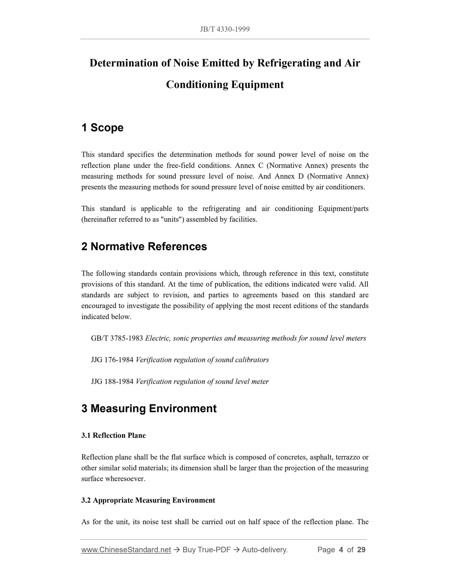
Determination of Noise Emitted by Refrigerating and Air
Conditioning Equipment
1 Scope
This standard specifies the determination methods for sound power level of noise on the
reflection plane under the free-field conditions. Annex C (Normative Annex) presents the
measuring methods for sound pressure level of noise. And Annex D (Normative Annex)
presents the measuring methods for sound pressure level of noise emitted by air conditioners.
This standard is applicable to the refrigerating and air conditioning Equipment/parts
(hereinafter referred to as "units") assembled by facilities.
2 Normative References
The following standards contain provisions which, through reference in this text, constitute
provisions of this standard. At the time of publication, the editions indicated were valid. All
standards are subject to revision, and parties to agreements based on this standard are
encouraged to investigate the possibility of applying the most recent editions of the standards
indicated below.
GB/T 3785-1983 Electric, sonic properties and measuring methods for sound level meters
JJG 176-1984 Verification regulation of sound calibrators
JJG 188-1984 Verification regulation of sound level meter
3 Measuring Environment
3.1 Reflection Plane
Reflection plane shall be the flat surface which is composed of concretes, asphalt, terrazzo or
other similar solid materials; its dimension shall be larger than the projection of the measuring
surface wheresoever.
3.2 Appropriate Measuring Environment
As for the unit, its noise test shall be carried out on half space of the reflection plane. The
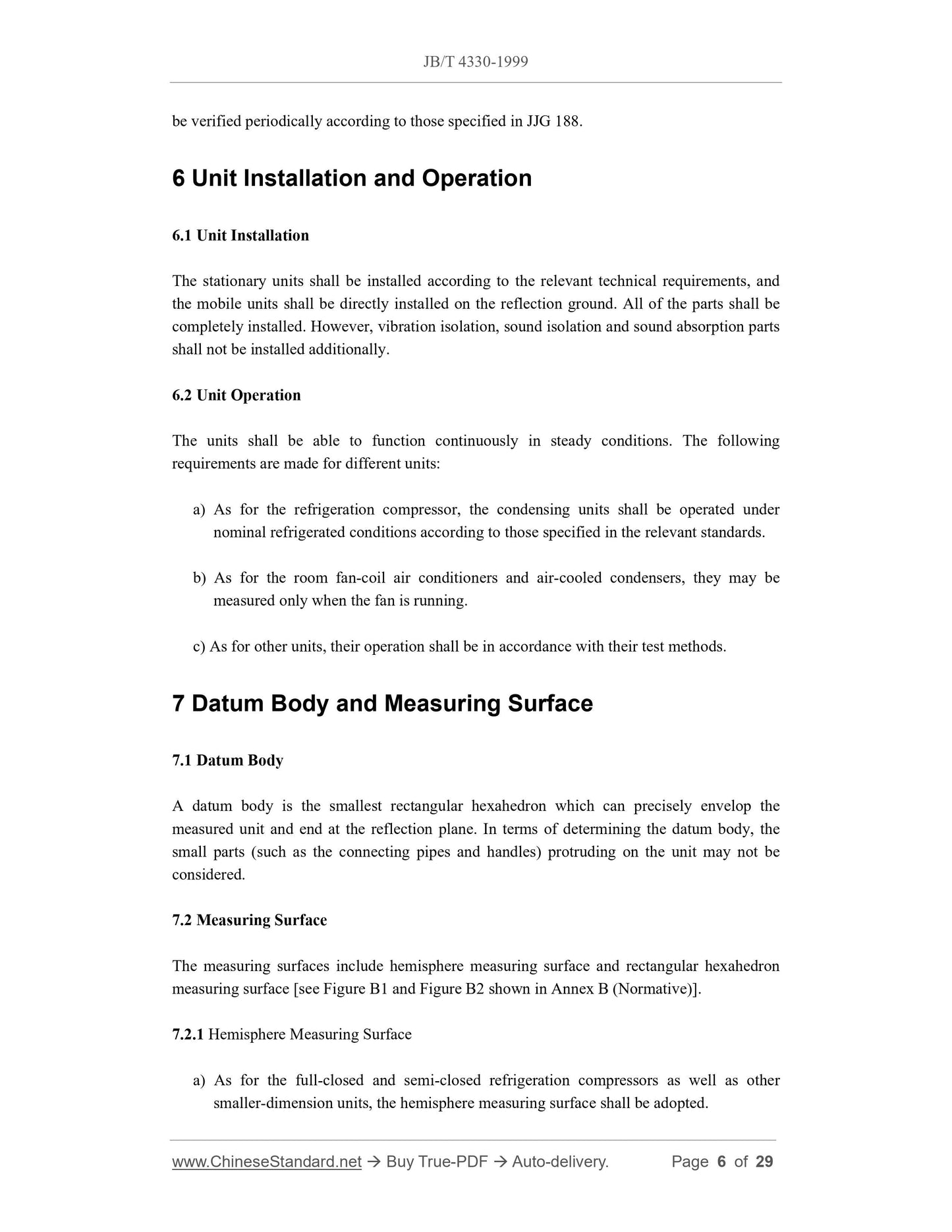
be verified periodically according to those specified in JJG 188.
6 Unit Installation and Operation
6.1 Unit Installation
The stationary units shall be installed according to the relevant technical requirements, and
the mobile units shall be directly installed on the reflection ground. All of the parts shall be
completely installed. However, vibration isolation, sound isolation and sound absorption parts
shall not be installed additionally.
6.2 Unit Operation
The units shall be able to function continuously in steady conditions. The following
requirements are made for different units:
a) As for the refrigeration compressor, the condensing units shall be operated under
nominal refrigerated conditions according to those specified in the relevant standards.
b) As for the room fan-coil air conditioners and air-cooled condensers, they may be
measured only when the fan is running.
c) As for other units, their operation shall be in accordance with their test methods.
7 Datum Body and Measuring Surface
7.1 Datum Body
A datum body is the smallest rectangular hexahedron which can precisely envelop the
measured unit and end at the reflection plane. In terms of determining the datum body, the
small parts (such as the connecting pipes and handles) protruding on the unit may not be
considered.
7.2 Measuring Surface
The measuring surfaces include hemisphere measuring surface and rectangular hexahedron
measuring surface [see Figure B1 and Figure B2 shown in Annex B (Normative)].
7.2.1 Hemisphere Measuring Surface
a) As for the full-closed and semi-closed refrigeration compressors as well as other
smaller-dimension units, the hemisphere measuring surface shall be adopted.
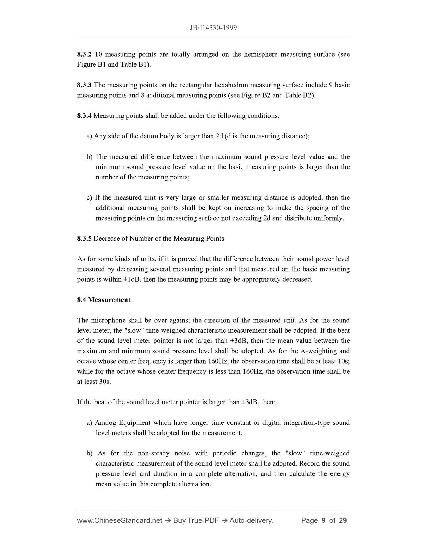
8.3.2 10 measuring points are totally arranged on the hemisphere measuring surface (see
Figure B1 and Table B1).
8.3.3 The measuring points on the rectangular hexahedron measuring surface include 9 basic
measuring points and 8 additional measuring points (see Figure B2 and Table B2).
8.3.4 Measuring points shall be added under the following conditions:
a) Any side of the datum body is larger than 2d (d is the measuring distance);
b) The measured difference between the maximum sound pressure level value and the
minimum sound pressure level value on the basic measuring points is larger than the
number of the measuring points;
c) If the measured unit is very large or smaller measuring distance is adopted, then the
additional measuring points shall be kept on increasing to make the spacing of the
measuring points on the measuring surface not exceeding 2d and distribute uniformly.
8.3.5 Decrease of Number of the Measuring Points
As for some kinds of units, if it is proved that the difference between their sound power level
measured by decreasing several measuring points and that measured on the basic measuring
points is within ±1dB, then the measuring points may be appropriately decreased.
8.4 Measurement
The microphone shall be over against the direction of the measured unit. As for the sound
level meter, the "slow" time-weighed characteristic measurement shall be adopted. If the beat
of the sound level meter pointer is not larger than ±3dB, then the mean value between the
maximum and minimum sound pressure level shall be adopted. As for the A-weighting and
octave whose center frequency is larger than 160Hz, the observation time shall be at least 10s;
while for the octave whose center frequency is less than 160Hz, the observation time shall be
at least 30s.
If the beat of the sound level meter pointer is larger than ±3dB, then:
a) Analog Equipment which have longer time constant or digital integration-type sound
level meters shall be adopted for the measurement;
b) As for the non-steady noise with periodic changes, the "slow" time-weighed
characteristic measurement of the sound level meter shall be adopted. Record the sound
pressure level and duration in a complete alternation, and then calculate the energy
mean value in this complete alternation.
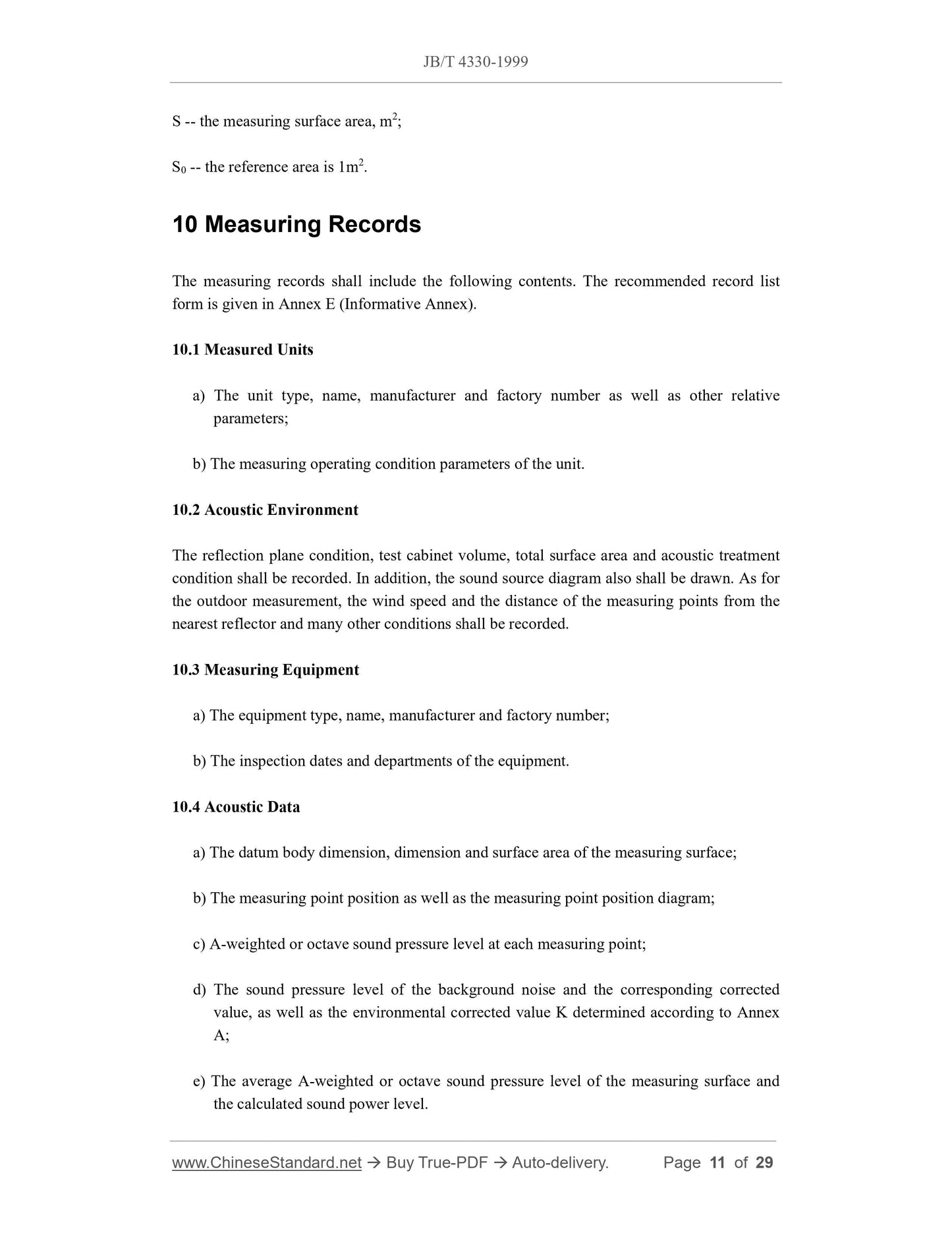
S -- the measuring surface area, m2;
S0 -- the reference area is 1m2.
10 Measuring Records
The measuring records shall include the following contents. The recommended record list
form is given in Annex E (Informative Annex).
10.1 Measured Units
a) The unit type, name, manufacturer and factory number as well as other relative
parameters;
b) The measuring operating condition parameters of the unit.
10.2 Acoustic Environment
The reflection plane condition, test cabinet volume, total surface area and acoustic treatment
condition shall be recorded. In addition, the sound source di...