

1
/
of
7
www.ChineseStandard.us -- Field Test Asia Pte. Ltd.
JB/T 10442.2-2017 English PDF (JB/T10442.2-2017)
JB/T 10442.2-2017 English PDF (JB/T10442.2-2017)
Regular price
$190.00
Regular price
Sale price
$190.00
Unit price
/
per
Shipping calculated at checkout.
Couldn't load pickup availability
JB/T 10442.2-2017: Insulating paper coated with resin binder forming rhombic pattern for electrical purposes - Part 2: Methods of test
Delivery: 9 seconds. Download (and Email) true-PDF + Invoice.Get Quotation: Click JB/T 10442.2-2017 (Self-service in 1-minute)
Newer / historical versions: JB/T 10442.2-2017
Preview True-PDF
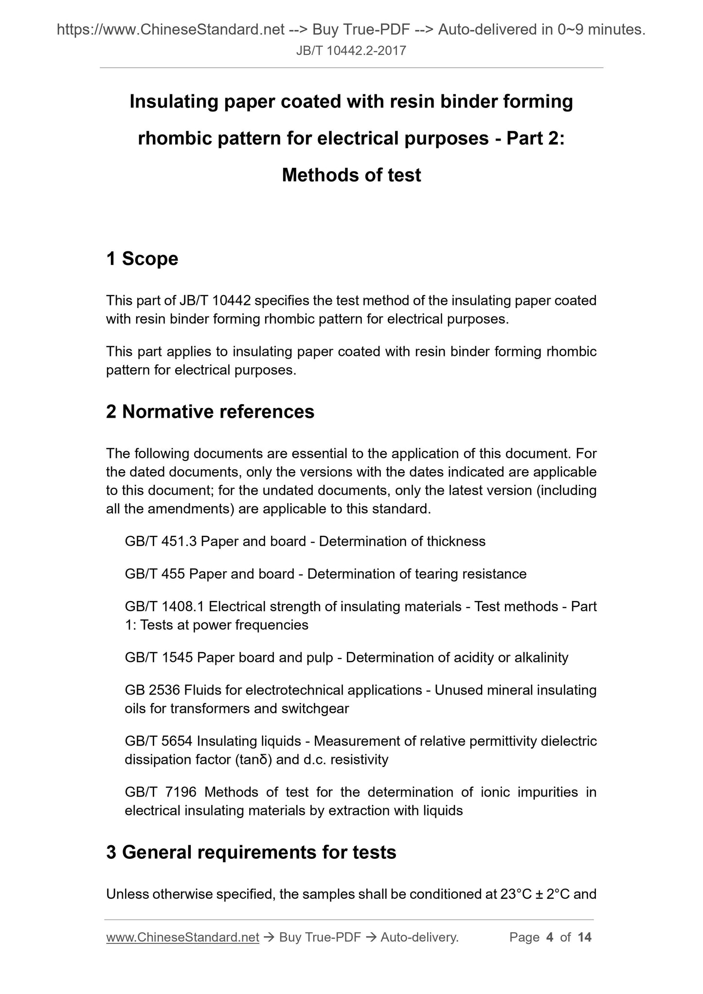
Scope
This part of JB/T 10442 specifies the test method of the insulating paper coatedwith resin binder forming rhombic pattern for electrical purposes.
This part applies to insulating paper coated with resin binder forming rhombic
pattern for electrical purposes.
Basic Data
| Standard ID | JB/T 10442.2-2017 (JB/T10442.2-2017) |
| Description (Translated English) | Insulating paper coated with resin binder forming rhombic pattern for electrical purposes - Part 2: Methods of test |
| Sector / Industry | Mechanical and Machinery Industry Standard (Recommended) |
| Classification of Chinese Standard | K15 |
| Word Count Estimation | 10,148 |
| Date of Issue | 2017-04-12 |
| Date of Implementation | 2018-01-01 |
| Older Standard (superseded by this standard) | JB/T 10442.2-2004 |
| Quoted Standard | GB/T 451.3; GB/T 455; GB/T 1408.1; GB/T 1545; GB 2536; GB/T 5654; GB/T 7196 |
| Regulation (derived from) | Ministry of Industry and Information Technology Bulletin 2017 No. 14; Industry Standard Filing Announcement 2017 No. 6 (Total No. 210) |
| Issuing agency(ies) | Ministry of Industry and Information Technology |
| Summary | This standard specifies the test method for electrical coated rhombic insulating paper. |
Share