Skip to product information
1 of 12

PayPal, credit cards. Download editable-PDF & invoice in 1 second!

JB/T 10215-2020 English PDF (JBT10215-2020)

JB/T 10215-2020 English PDF (JBT10215-2020)

Regular price $200.00 USD
Regular price Sale price $200.00 USD
Sale Sold out
Shipping calculated at checkout.
Quotation: In 1-minute, 24-hr self-service. Click here JB/T 10215-2020 to get it for Purchase Approval, Bank TT...

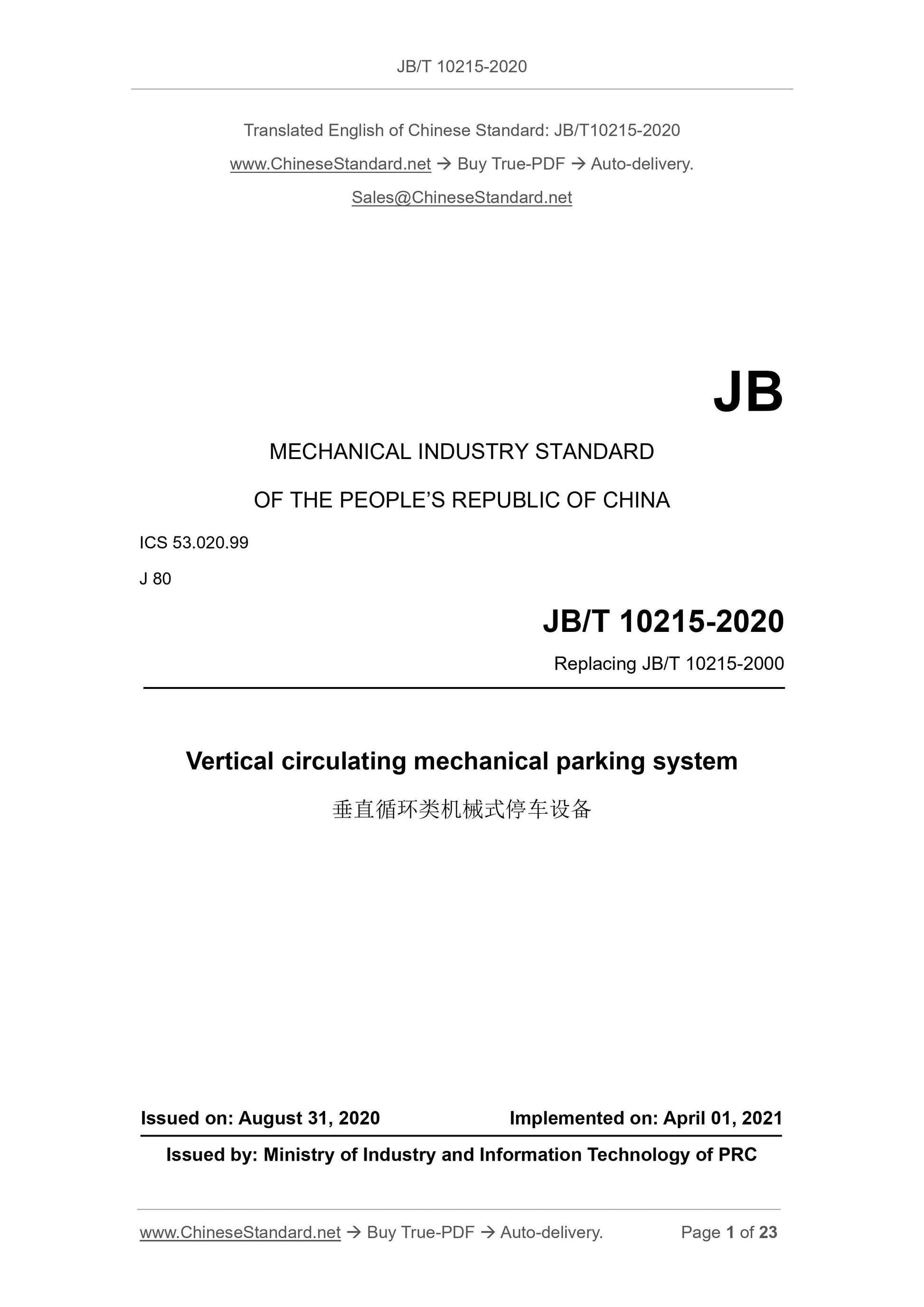
JB/T 10215-2020: Vertical circulating mechanical parking system

This standard specifies the terms and definitions, types, basic parameters, technical requirements, test methods, inspection rules, marking, packaging, transportation, storage of vertical circulating mechanical parking system. This standard applies to the vertical circulating mechanical parking system (hereinafter referred to as equipment), which is defined in GB/T 26476.
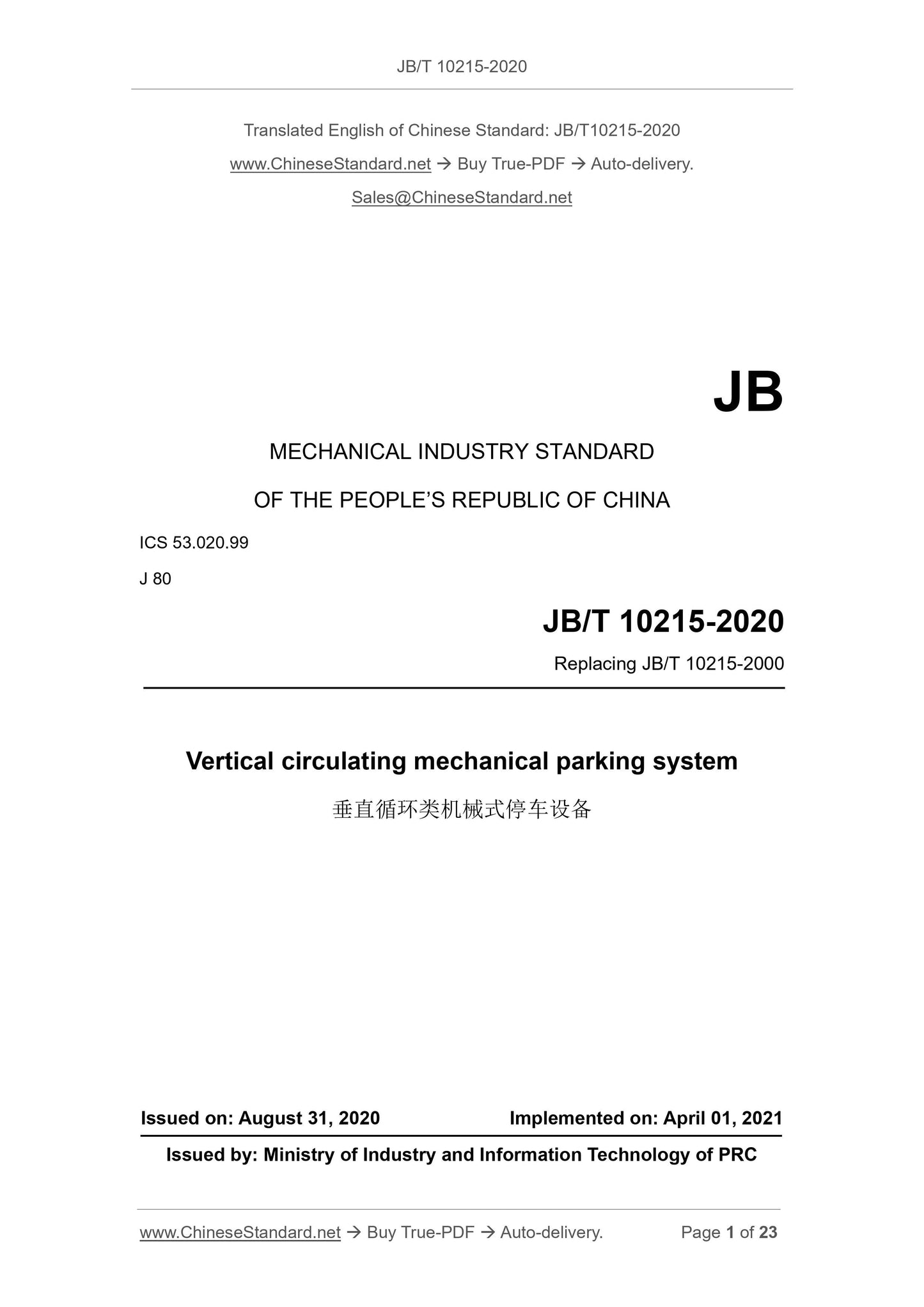
JB/T 10215-2020
JB
MECHANICAL INDUSTRY STANDARD
OF THE PEOPLE’S REPUBLIC OF CHINA
ICS 53.020.99
J 80
Replacing JB/T 10215-2000
Vertical circulating mechanical parking system
ISSUED ON: AUGUST 31, 2020
IMPLEMENTED ON: APRIL 01, 2021
Issued by: Ministry of Industry and Information Technology of PRC
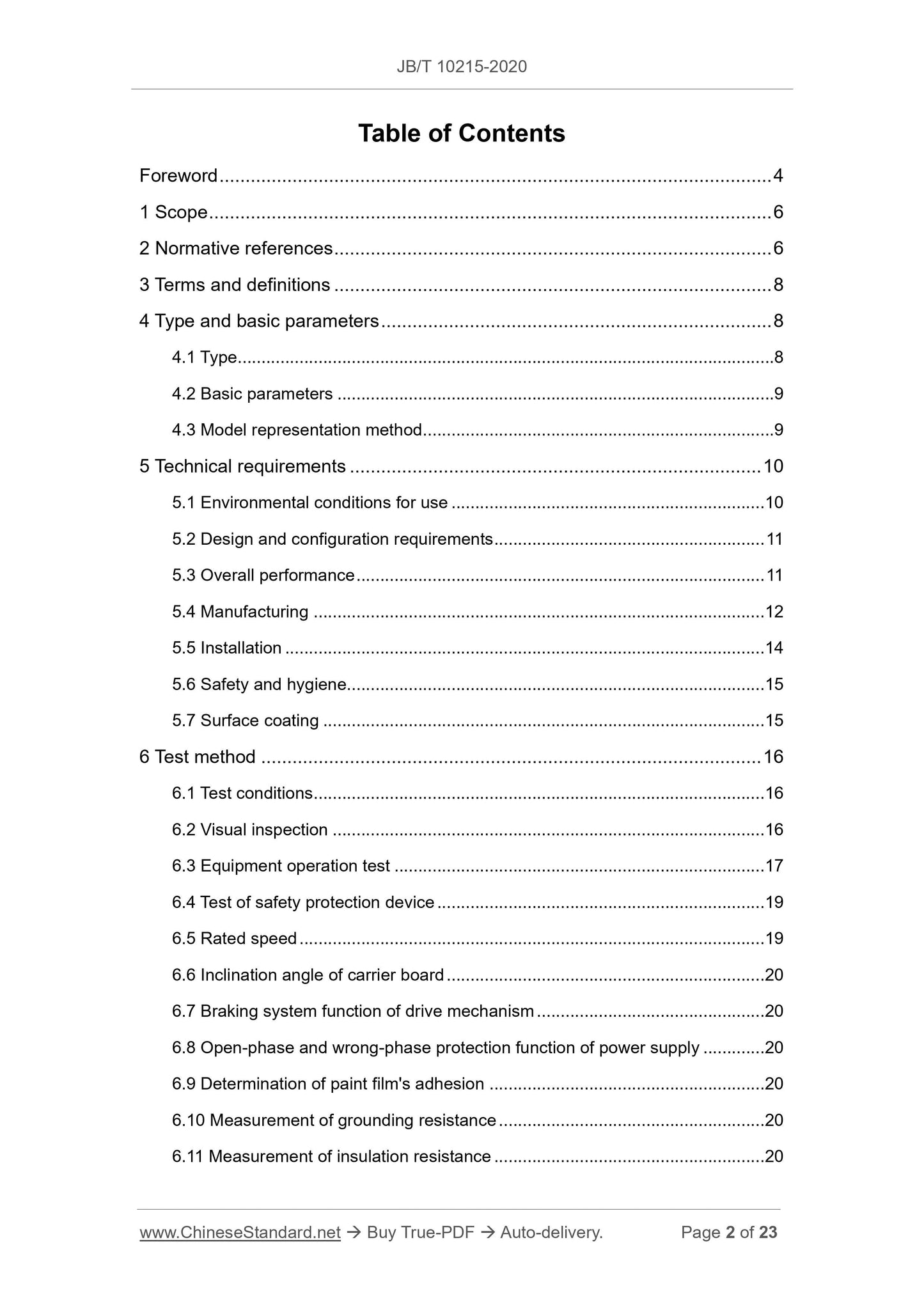
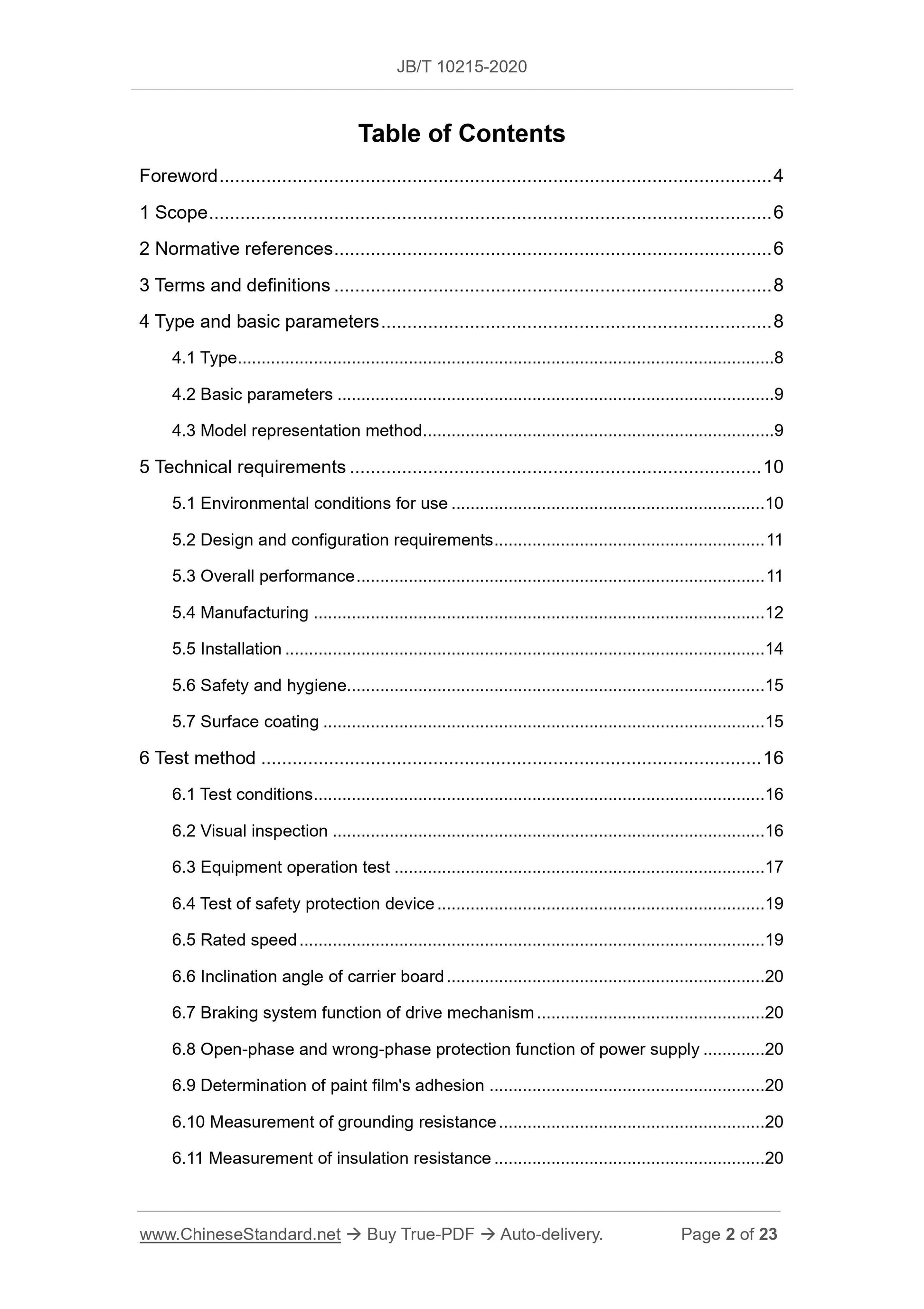
Table of Contents
Foreword ... 4
1 Scope ... 6
2 Normative references ... 6
3 Terms and definitions ... 8
4 Type and basic parameters ... 8
4.1 Type ... 8
4.2 Basic parameters ... 9
4.3 Model representation method ... 9
5 Technical requirements ... 10
5.1 Environmental conditions for use ... 10
5.2 Design and configuration requirements ... 11
5.3 Overall performance ... 11
5.4 Manufacturing ... 12
5.5 Installation ... 14
5.6 Safety and hygiene... 15
5.7 Surface coating ... 15
6 Test method ... 16
6.1 Test conditions ... 16
6.2 Visual inspection ... 16
6.3 Equipment operation test ... 17
6.4 Test of safety protection device ... 19
6.5 Rated speed ... 19
6.6 Inclination angle of carrier board ... 20
6.7 Braking system function of drive mechanism ... 20
6.8 Open-phase and wrong-phase protection function of power supply ... 20 6.9 Determination of paint film's adhesion ... 20
6.10 Measurement of grounding resistance ... 20
6.11 Measurement of insulation resistance ... 20
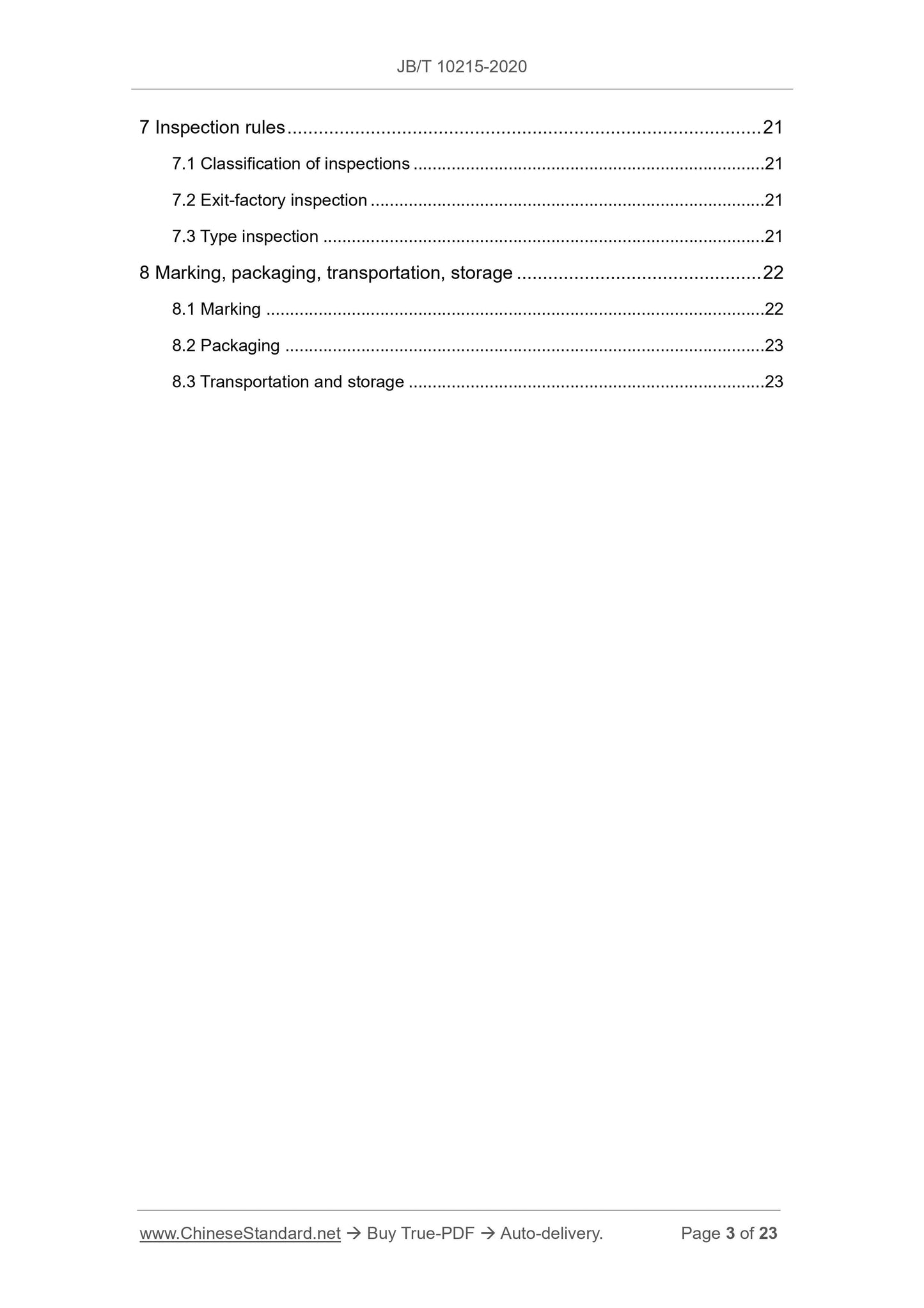
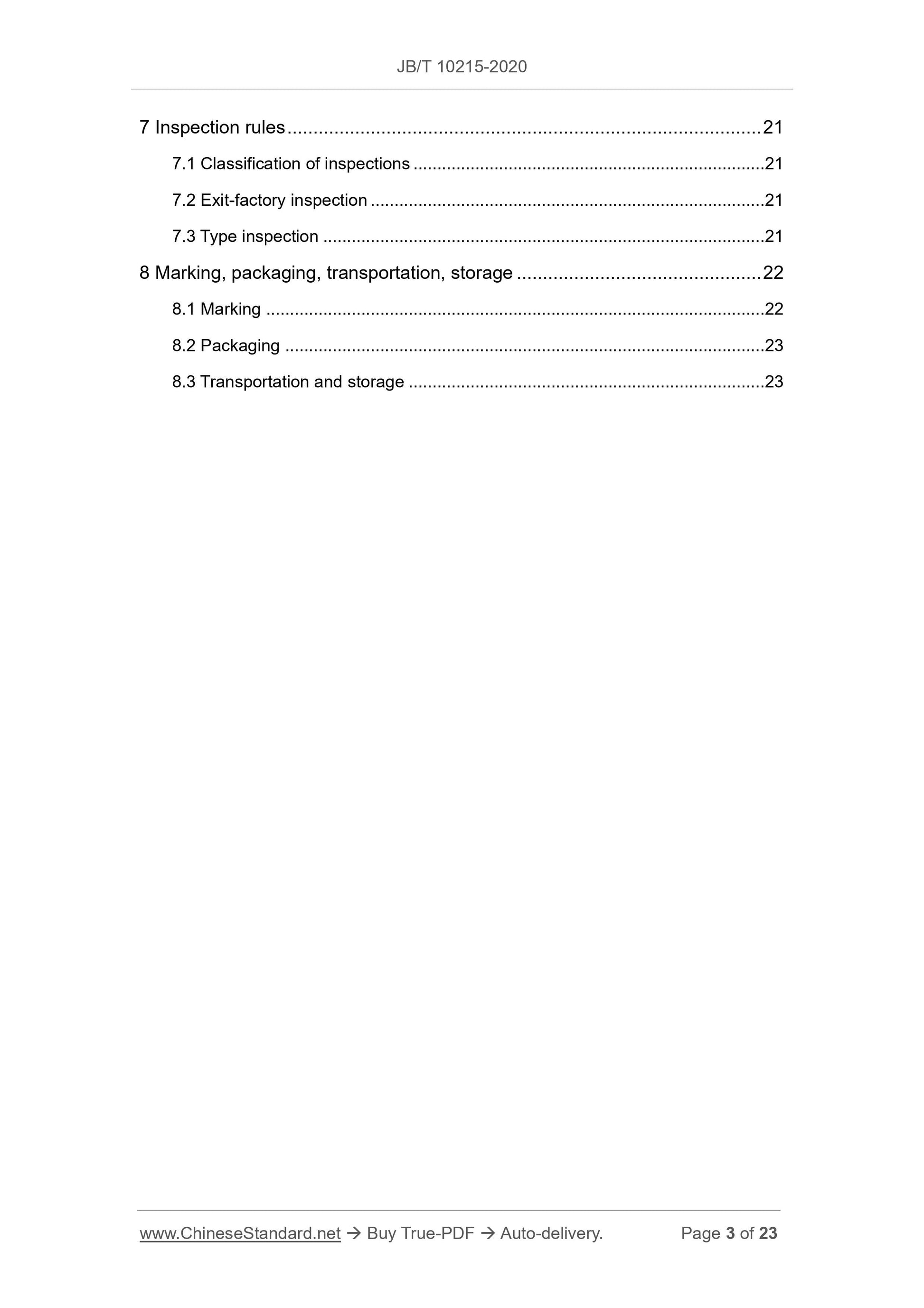
7 Inspection rules ... 21
7.1 Classification of inspections ... 21
7.2 Exit-factory inspection ... 21
7.3 Type inspection ... 21
8 Marking, packaging, transportation, storage ... 22
8.1 Marking ... 22
8.2 Packaging ... 23
8.3 Transportation and storage ... 23
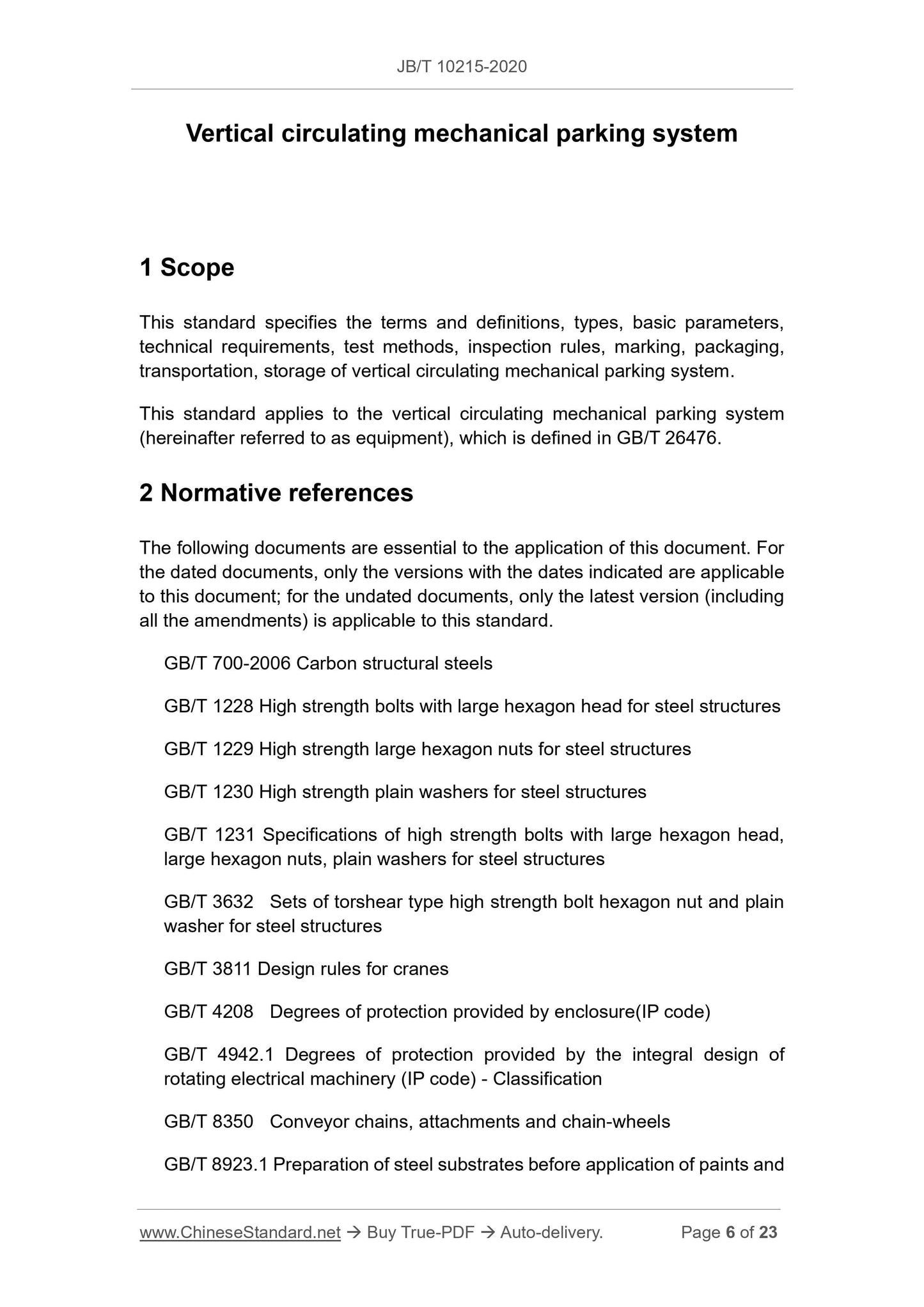
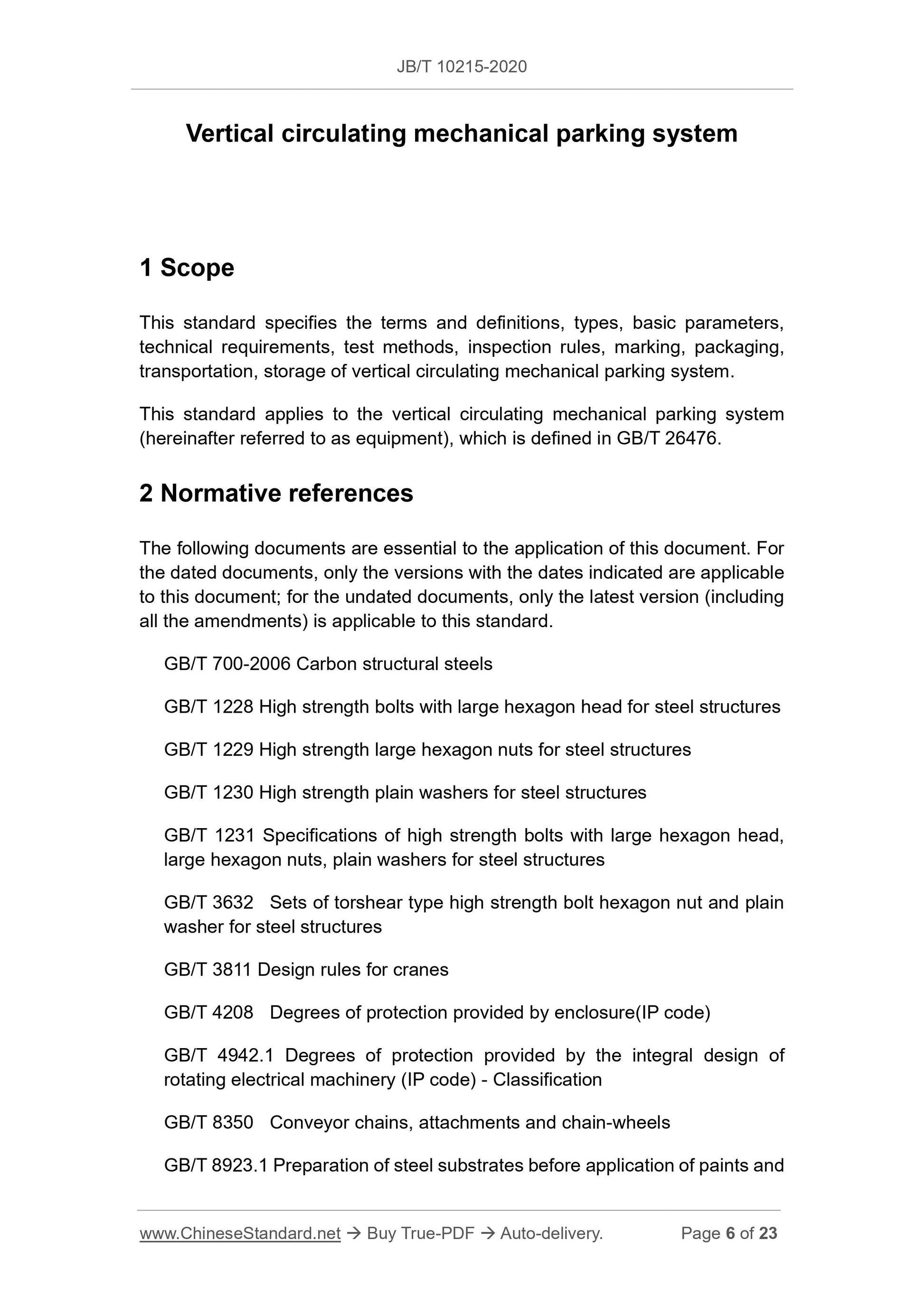
Vertical circulating mechanical parking system
1 Scope
This standard specifies the terms and definitions, types, basic parameters, technical requirements, test methods, inspection rules, marking, packaging, transportation, storage of vertical circulating mechanical parking system. This standard applies to the vertical circulating mechanical parking system (hereinafter referred to as equipment), which is defined in GB/T 26476. 2 Normative references
The following documents are essential to the application of this document. For the dated documents, only the versions with the dates indicated are applicable to this document; for the undated documents, only the latest version (including all the amendments) is applicable to this standard.
GB/T 700-2006 Carbon structural steels
GB/T 1228 High strength bolts with large hexagon head for steel structures GB/T 1229 High strength large hexagon nuts for steel structures
GB/T 1230 High strength plain washers for steel structures
GB/T 1231 Specifications of high strength bolts with large hexagon head, large hexagon nuts, plain washers for steel structures
GB/T 3632 Sets of torshear type high strength bolt hexagon nut and plain washer for steel structures
GB/T 3811 Design rules for cranes
GB/T 4208 Degrees of protection provided by enclosure(IP code)
GB/T 4942.1 Degrees of protection provided by the integral design of
rotating electrical machinery (IP code) - Classification
GB/T 8350 Conveyor chains, attachments and chain-wheels
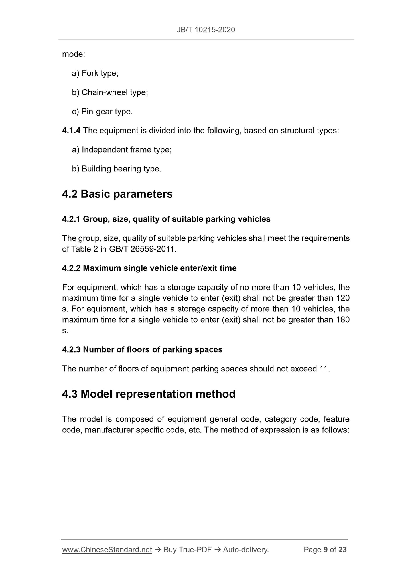
GB/T 8923.1 Preparation of steel substrates before application of paints and mode:
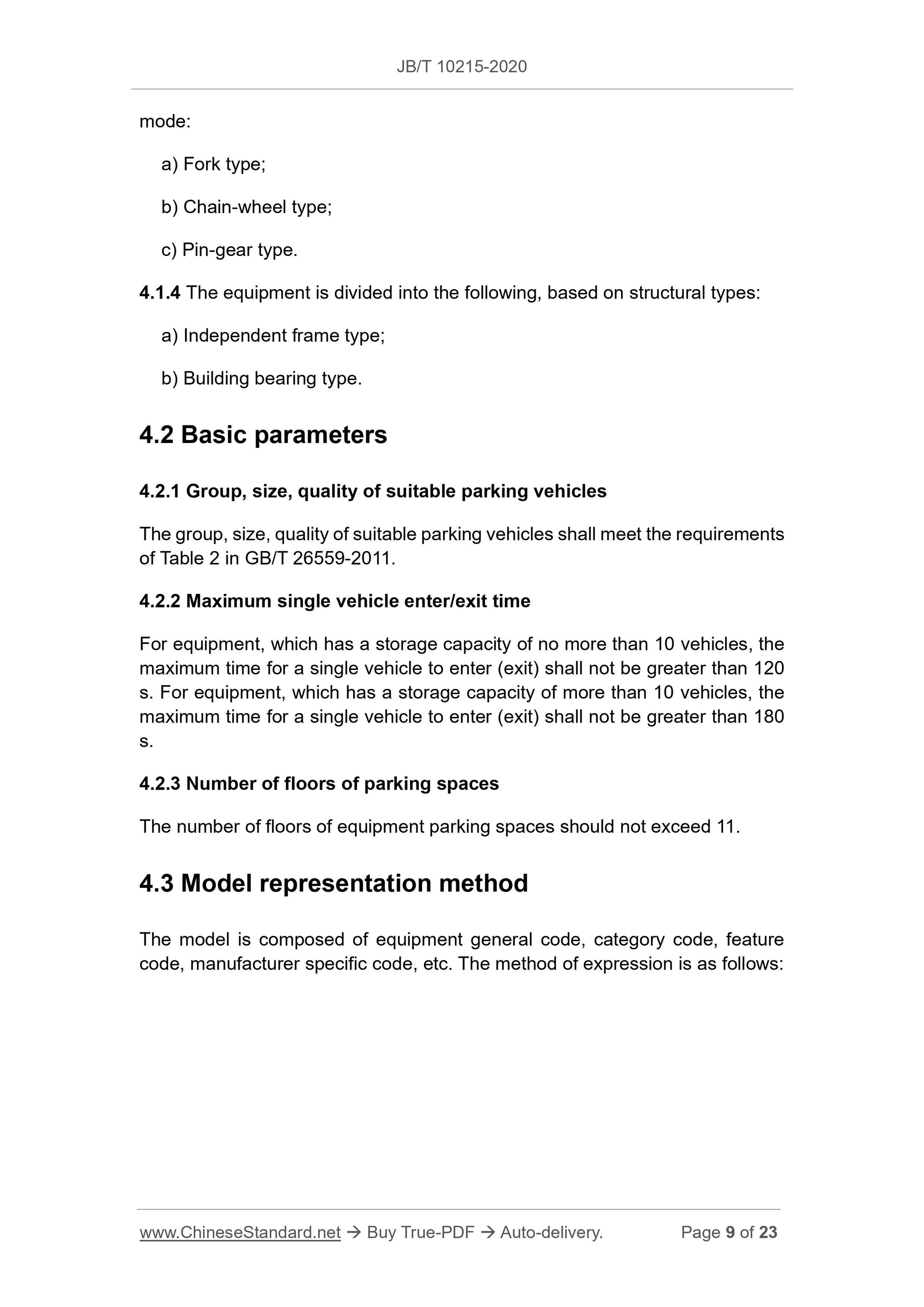
a) Fork type;
b) Chain-wheel type;
c) Pin-gear type.
4.1.4 The equipment is divided into the following, based on structural types: a) Independent frame type;
b) Building bearing type.
4.2 Basic parameters
4.2.1 Group, size, quality of suitable parking vehicles
The group, size, quality of suitable parking vehicles shall meet the requirements of Table 2 in GB/T 26559-2011.
4.2.2 Maximum single vehicle enter/exit time
For equipment, which has a storage capacity of no more than 10 vehicles, the maximum time for a single vehicle to enter (exit) shall not be greater than 120 s. For equipment, which has a storage capacity of more than 10 vehicles, the maximum time for a single vehicle to enter (exit) shall not be greater than 180 s.
4.2.3 Number of floors of parking spaces
The number of floors of equipment parking spaces should not exceed 11.
4.3 Model representation method
The model is composed of equipment general code, category code, feature code, manufacturer specific code, etc. The method of expression is as follows: 5.1.3 The altitude shall not exceed 1000 m.
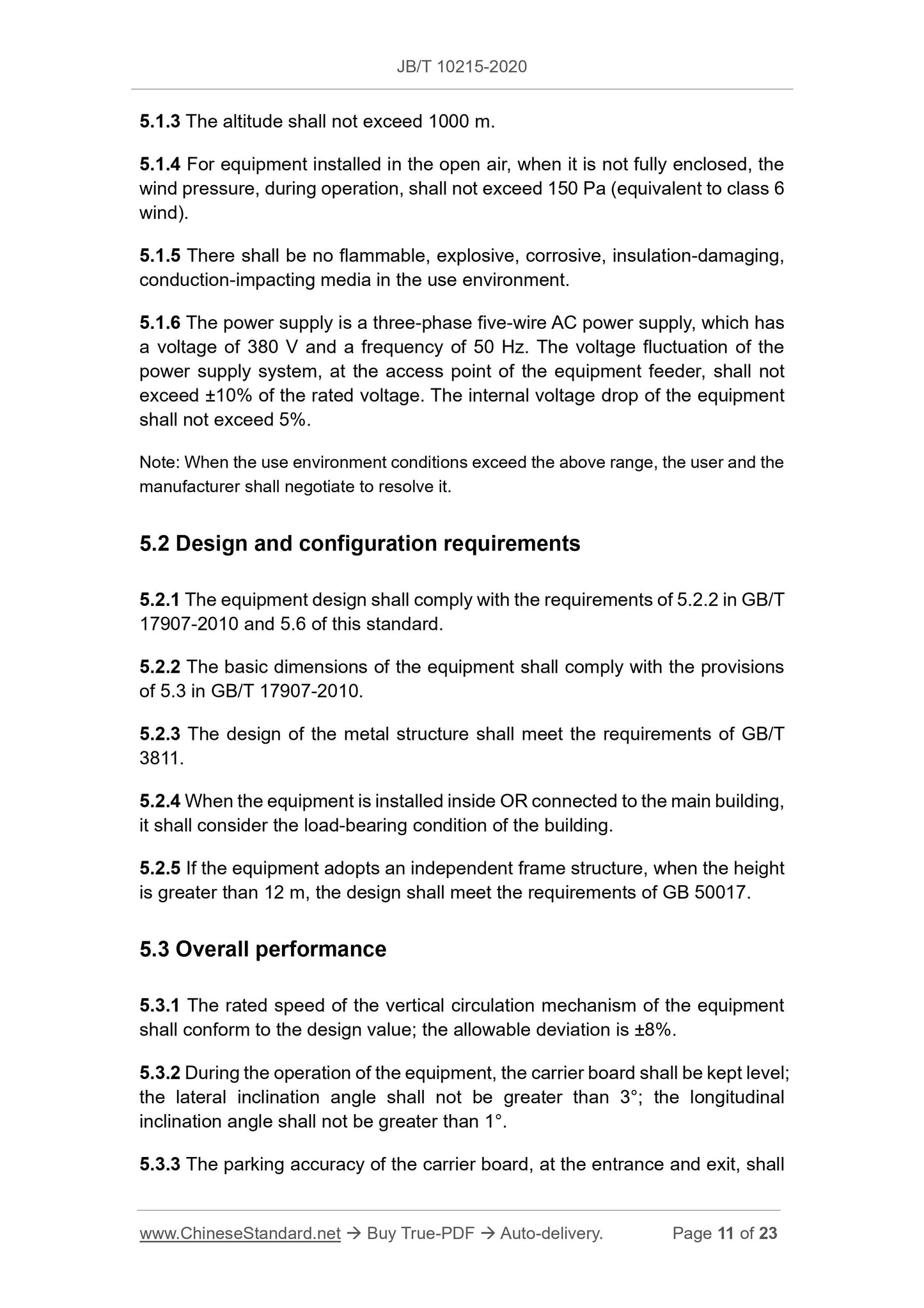
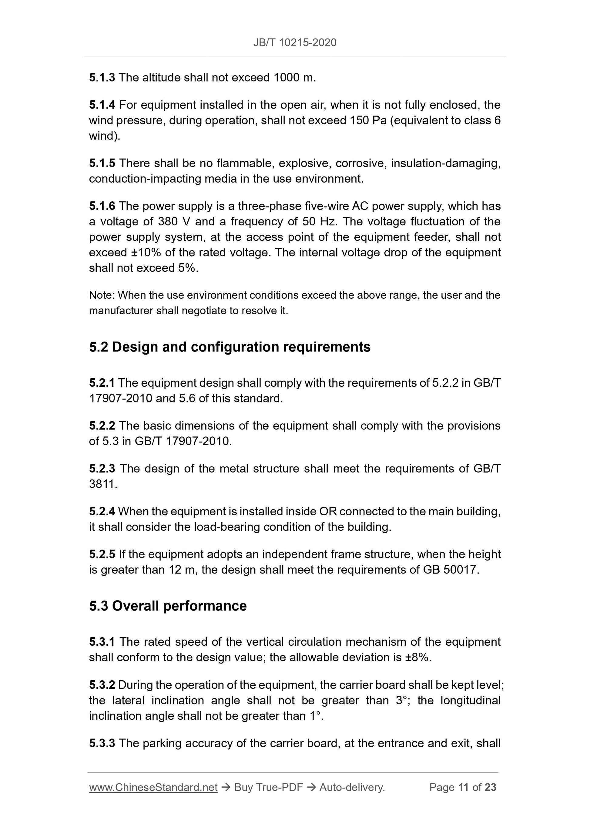
5.1.4 For equipment installed in the open air, when it is not fully enclosed, the wind pressure, during operation, shall not exceed 150 Pa (equivalent to class 6 wind).
5.1.5 There shall be no flammable, explosive, corrosive, insulation-damaging, conduction-impacting media in the use environment.
5.1.6 The power supply is a three-phase five-wire AC power supply, which has a voltage of 380 V and a frequency of 50 Hz. The voltage fluctuation of the power supply system, at the access point of the equipment feeder, shall not exceed ±10% of the rated voltage. The internal voltage drop of the equipment shall not exceed 5%.
Note: When the use environment conditions exceed the above range, the user and the manufacturer shall negotiate to resolve it.
5.2 Design and configuration requirements
5.2.1 The equipment design shall comply with the requirements of 5.2.2 in GB/T 17907-2010 and 5.6 of this standard.
5.2.2 The basic dimensions of the equipment shall comply with the provisions of 5.3 in GB/T 17907-2010.
5.2.3 The design of the metal structure shall meet the requirements of GB/T 3811.
5.2.4 When the equipment is installed inside OR connected to the main building, it shall consider the load-bearing condition of the building.
5.2.5 If the equipment adopts an independent frame structure, when the height is greater than 12 m, the design shall meet the requirements of GB 50017. 5.3 Overall performance
5.3.1 The rated speed of the vertical circulation mechanism of the equipment shall conform to the design value; the allowable deviation is ±8%.
5.3.2 During the operation of the equipment, the carrier board shall be kept level; the lateral inclination angle shall not be greater than 3°; the longitudinal inclination angle shall not be greater than 1°.
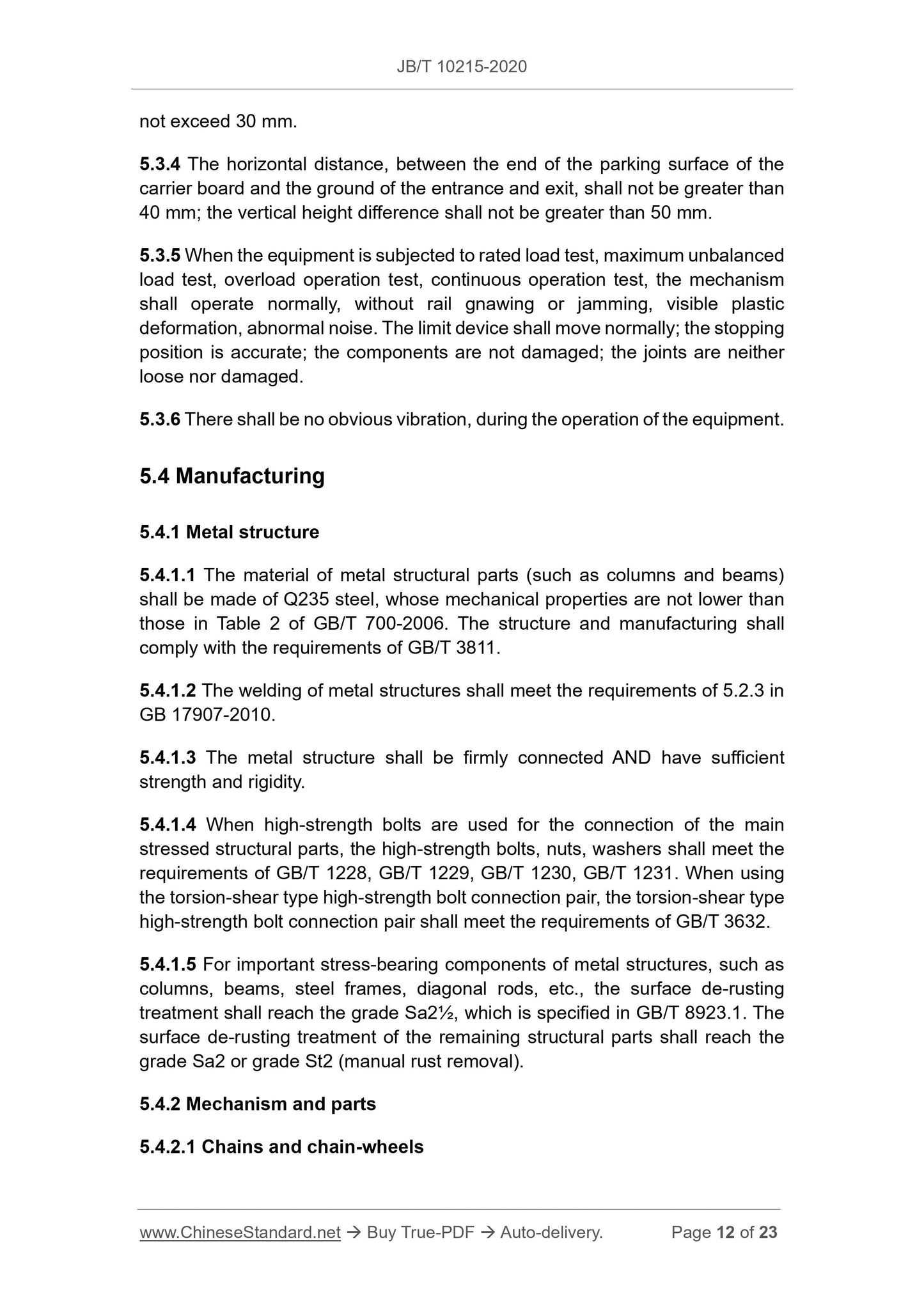
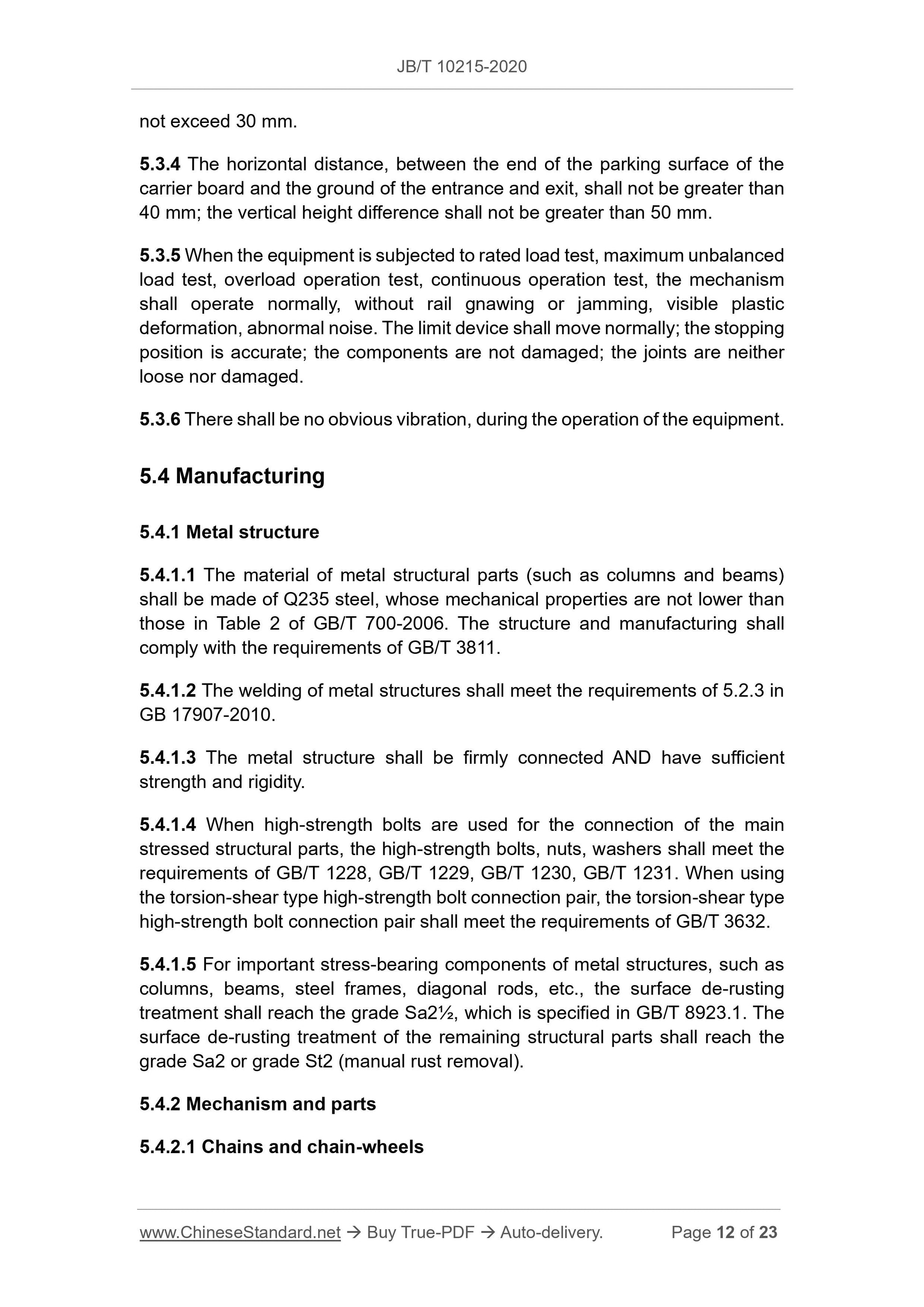
5.3.3 The parking accuracy of the carrier board, at the entrance and exit, shall not exceed 30 mm.
5.3.4 The horizontal distance, between the end of the parking surface of the carrier board and the ground of the entrance and exit, shall not be greater than 40 mm; the vertical height difference shall not be greater than 50 mm.
5.3.5 When the equipment is subjected to rated load test, maximum unbalanced load test, overload operation test, continuous operation test, the mechanism shall operate normally, without rail gnawing or jamming, visible plastic deformation, abnormal noise. The limit device shall move normally; the stopping position is accurate; the components are not damaged; the joints are neither loose nor damaged.
5.3.6 There shall be no obvious vibration, during the operation of the equipment. 5.4 Manufacturing
5.4.1 Metal structure
5.4.1.1 The material of metal structural parts (such as columns and beams) shall be made of Q235 steel, whose mechanical properties are not lower than those in Table 2 of GB/T 700-2006. The structure and manufacturing shall comply with the requirements of GB/T 3811.
5.4.1.2 The welding of metal structures shall meet the requirements of 5.2.3 in GB 17907-2010.
5.4.1.3 The metal structure shall be firmly connected AND have sufficient strength and rigidity.
5.4.1.4 When high-strength bolts are used for the connection of the main stressed structural parts, the high-strength bolts, nuts, washers shall meet the requirements of GB/T 1228, GB/T 1229, GB/T 1230, GB/T 1231. When using
the torsion-shear type high-strength bolt connection pair, the torsion-shear type high-strength bolt connection pair shall meet the requirements of GB/T 3632. 5.4.1.5 For important stress-bearing components of metal structures, such as columns, beams, steel frames, diagonal rods, etc., the surface de-rusting treatment shall reach the grade Sa2½, which is specified in GB/T 8923.1. The surface de-rusting treatment of the remaining structural parts shall reach the grade Sa2 or grade St2 (manual rust removal).
5.4.2 Mechanism and parts
5.4.2.1 Chains and chain-wheels
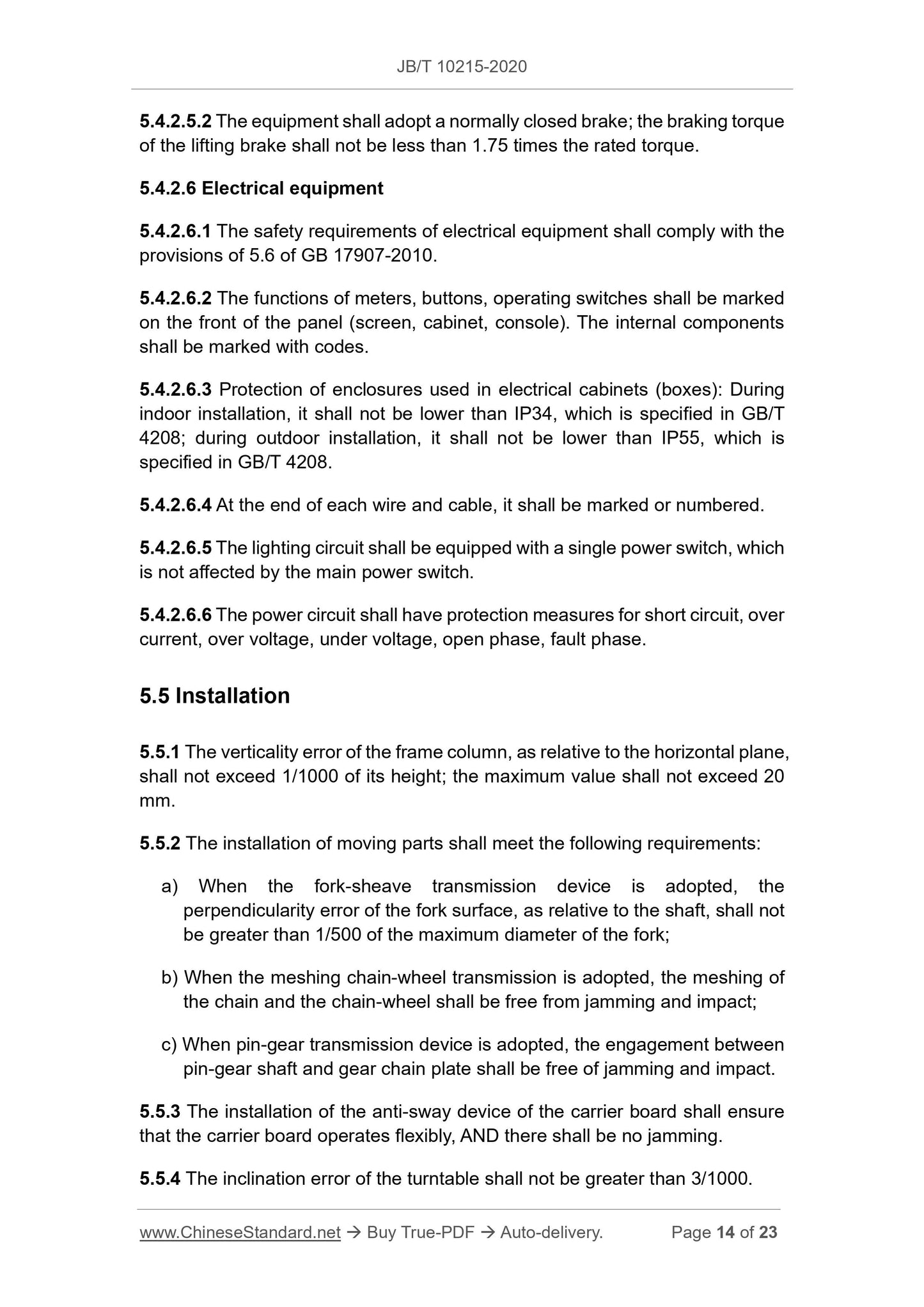
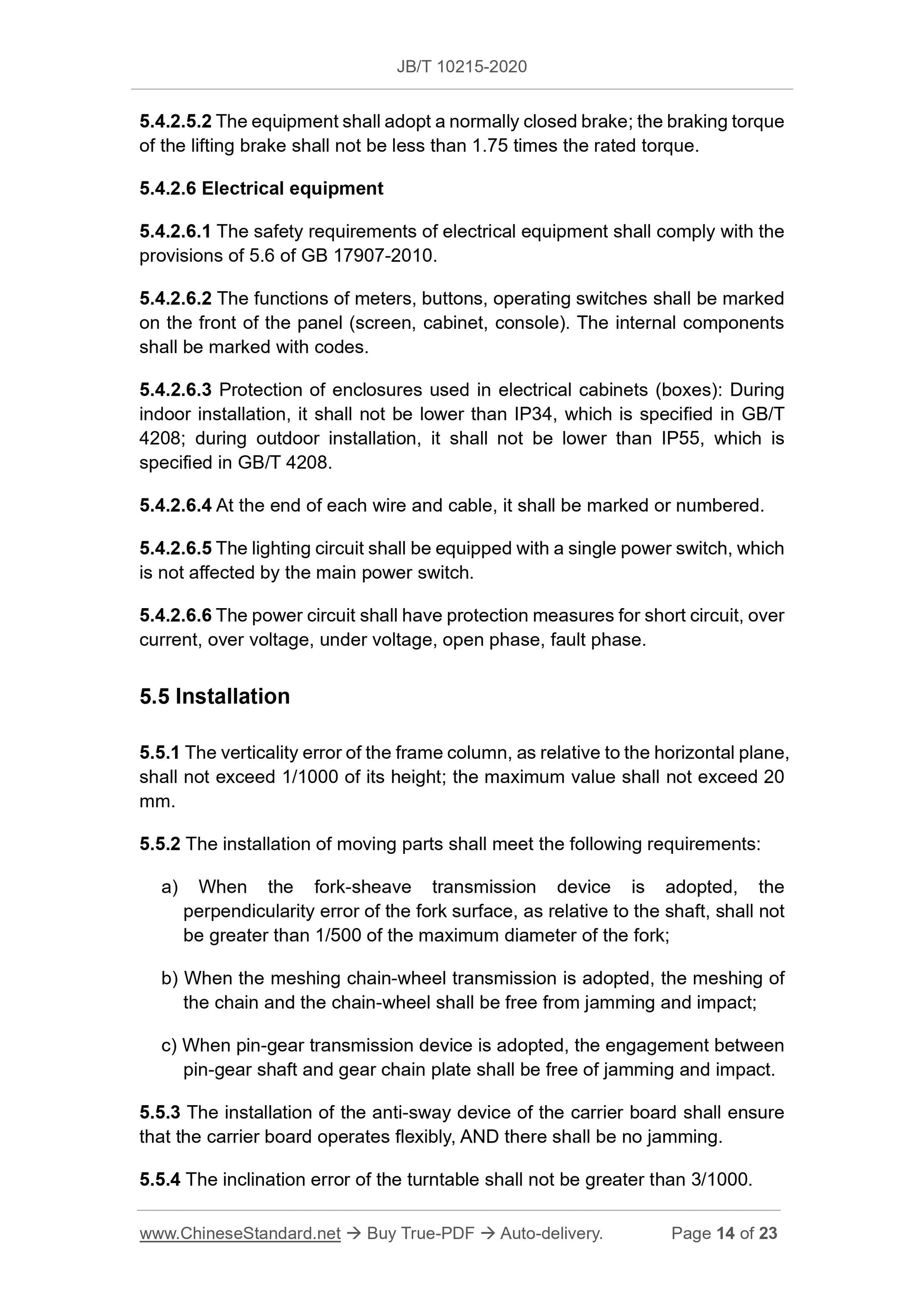
5.4.2.5.2 The equipment shall adopt a normally closed brake; the braking torque of the lifting brake shall not be less than 1.75 times the rated torque. 5.4.2.6 Electrical equipment
5.4.2.6.1 The safety requirements of electrical equipment shall comply with the provisions of 5.6 of GB 17907-2010.
5.4.2.6.2 The functions of meters, buttons, operating switches shall be marked on the front of the panel (screen, cabinet, console). The internal components shall be marked with codes.
5.4.2.6.3 Protection of enclosures used in electrical cabinets (boxes): During indoor installation, it shall not be lower than IP34, which is specified in GB/T 4208; during outdoor installation, it shall not be lower than IP55, which is specified in GB/T 4208.
5.4.2.6.4 At the end of each wire and cable, it shall be marked or numbered. 5.4.2.6.5 The lighting circuit shall be equipped with a single power switch, which is not affected by the main power switch.
5.4.2.6.6 The power circuit shall have protection measures for short circuit, over current, over voltage, under voltage, open phase, fault phase.
5.5 Installation
5.5.1 The verticality error of the frame column, as relative to the horizontal plane, shall not exceed 1/1000 of its height; the maximum value shall not exceed 20 mm.
5.5.2 The installation of moving parts shall meet the following requirements: a) When the fork-sheave transmission device is adopted, the
perpendicularity error of the fork surface, as relative to the shaft, shall not be greater than 1/500 of the maximum diameter of the fork;
b) When the meshing chain-wheel transmission is adopted, the meshing of the chain and the chain-wheel shall be free from jamming and impact;
c) When pin-gear transmission device is adopted, the engagement between pin-gear shaft and gear chain plate shall be free of jamming and impact. 5.5.3 The installation of the anti-sway device of the carrier board shall ensure that the carrier board operates flexibly, AND there shall be no jamming. 5.5.4 The inclination error of the turntable shall not be greater than 3/1000. 5.5.5 The installation of electrical equipment shall meet the requirements of GB 50168, GB 50169, GB 50254, GB 50256.
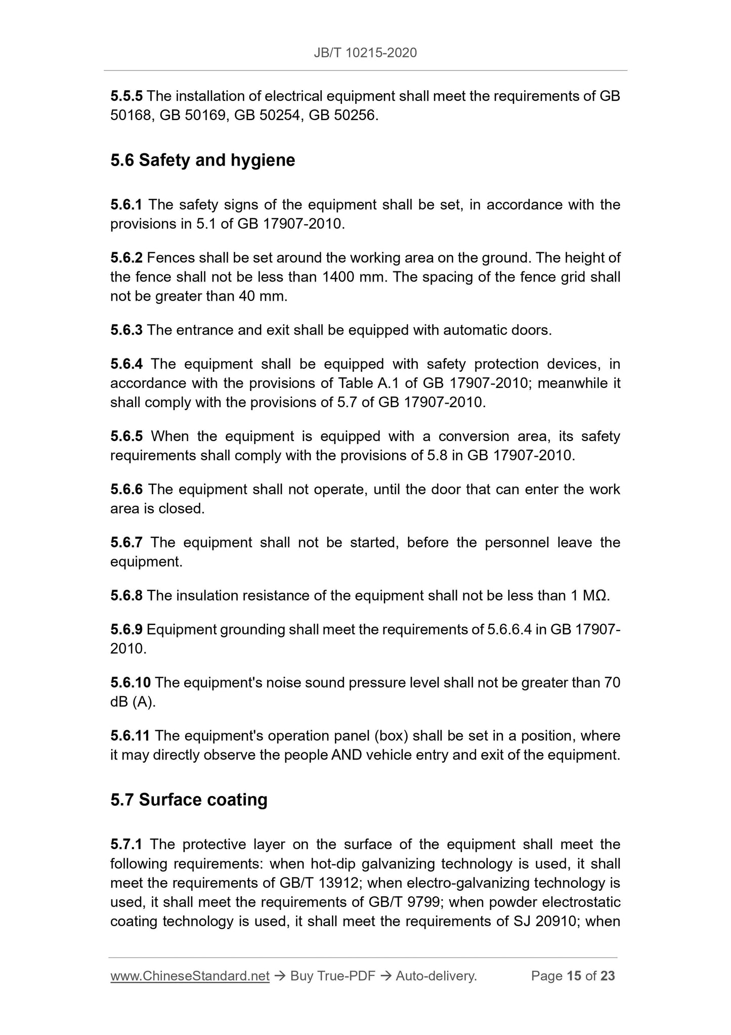
5.6 Safety and hygiene
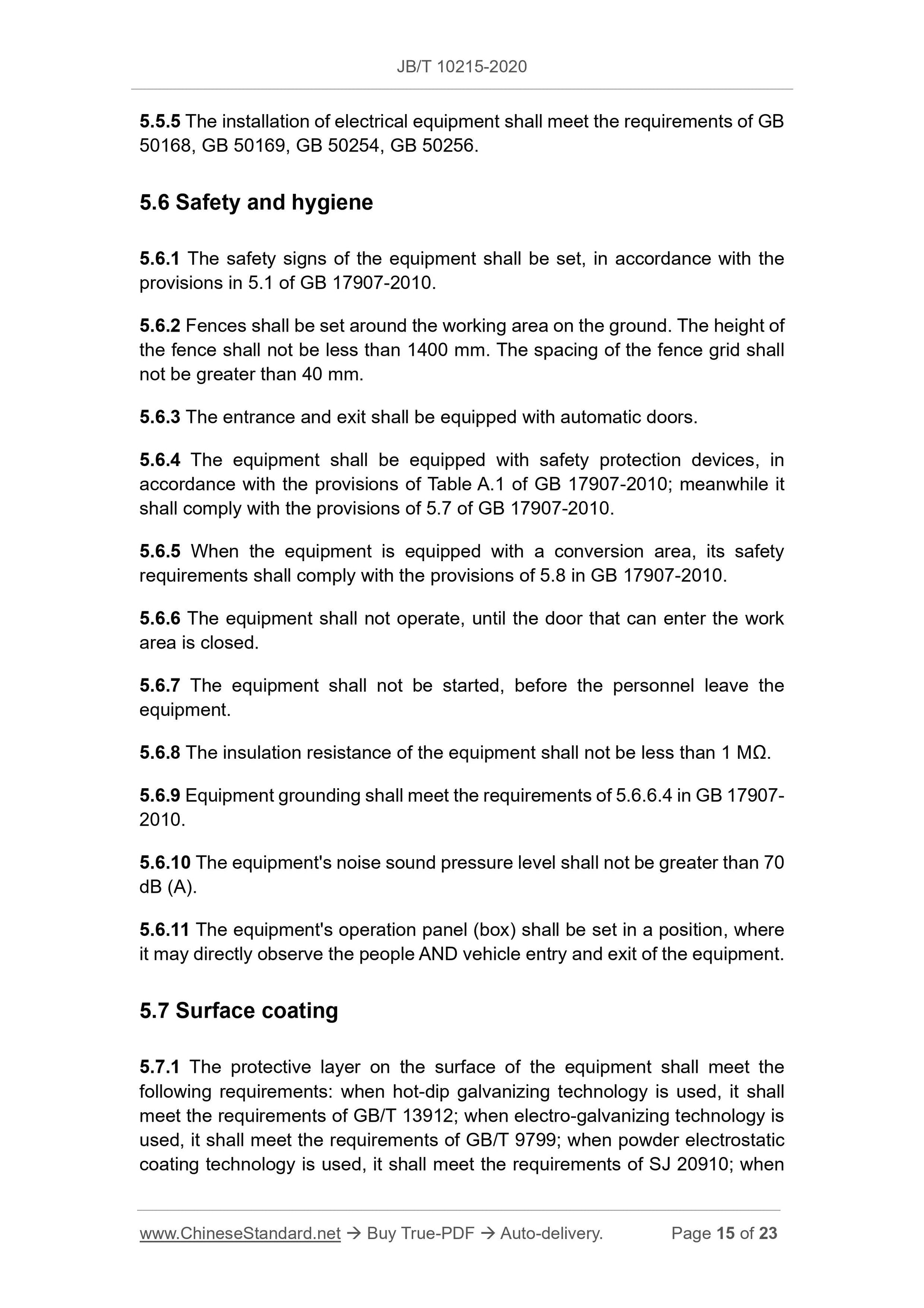
5.6.1 The safety signs of the equipment shall be set, in accordance with the provisions in 5.1 of GB 17907-2010.
5.6.2 Fences shall be set around the working area on the ground. The height of the fence shall not be less than 1400 mm. The spacing of the fence grid shall not be greater than 40 mm.
5.6.3 The entrance and exit shall be equipped with automatic doors.
5.6.4 The equipment shall be equipped with safety protection devices, in accordance with the provisions of Table A.1 of GB 17907-2010; meanwhile it shall comply with the provisions of 5.7 of GB 17907-2010.
5.6.5 When the equipment is equipped with a conversion area, its safety requirements shall comply with the provisions of 5.8 in GB 17907-2010.
5.6.6 The equipment shall not operate, until the door that can enter the work area is closed.
5.6.7 The equipment shall not be started, before the personnel leave the equipment.
5.6.8 The insulation resistance of the equipment shall not be less than 1 MΩ. 5.6.9 Equipment grounding shall meet the requirements of 5.6.6.4 in GB 17907- 2010.
5.6.10 The equipment's noise sound pressure level shall not be greater than 70 dB (A).
5.6.11 The equipment's operation panel (box) shall be set in a position, where it may directly observe the people AND vehicle entry and exit of the equipment. 5.7 Surface coating
5.7.1 The protective layer on the surface of the equipment shall meet the following requirements: when hot-dip galvanizing technology is used, it shall meet the requirements of GB/T 13912; when electro-galvanizing technology is used, it shall meet the requirements of GB/T 9799; when powder electrostatic coating technology is used, it shall meet the requirements of SJ 20910; when - The metal structure and connecting parts of the equipment, the carrier board, the operating status of each movement mechanism, the chain and
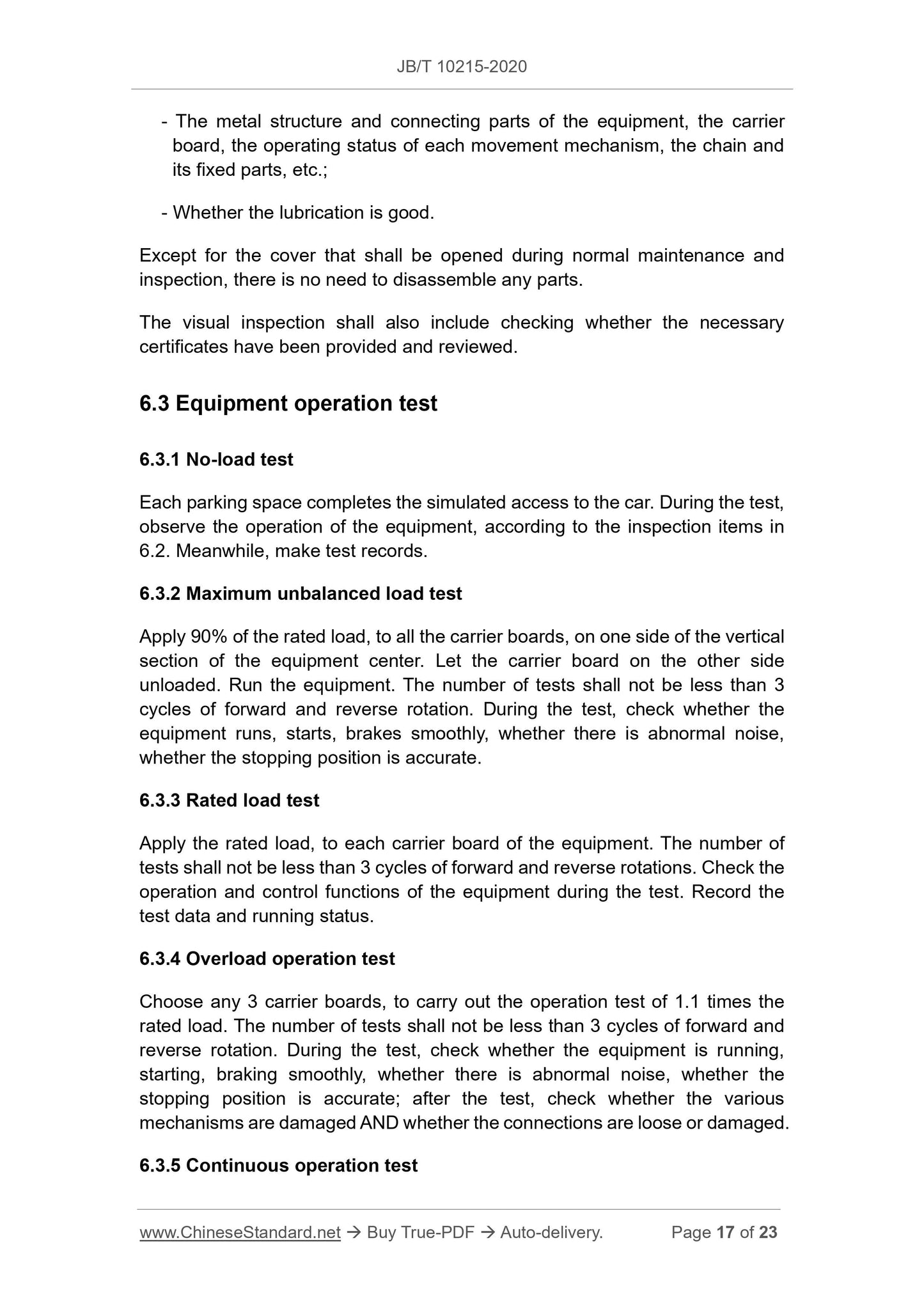
its fixed parts, etc.;
- Whether the lubrication is good.
Except for the cover that shall be opened during normal maintenance and inspection, there is no need to disassemble any parts.
The visual inspection shall also include checking whether the necessary certificates have been provided and reviewed.
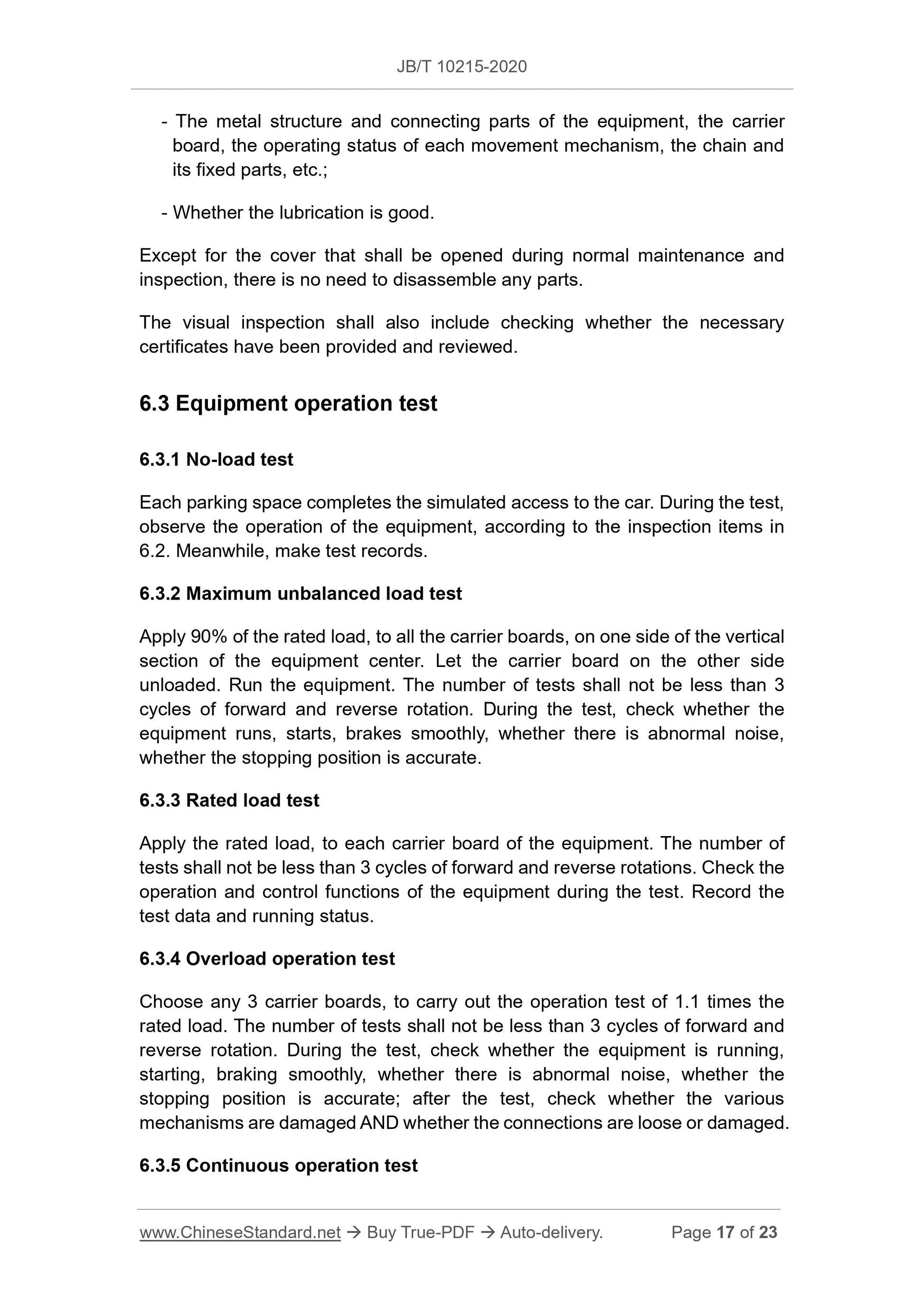
6.3 Equipment operation test
6.3.1 No-load test
Each parking space completes the simulated access to the car. During the test, observe the operation of the equipment, according to the inspection items in 6.2. Meanwhile, make test records.
6.3.2 Maximum unbalanced load test
Apply 90% of the rated load, to all the carrier boards, on one side of the vertical section of the equipment center. Let the carrier board on the other side unloaded. Run the equipment. The number of tests shall not be less than 3 cycles of forward and reverse rotation. During the test, check whether the equipment runs, starts, brakes smoothly, whether there is abnormal noise, whether the stopping position is accurate.
6.3.3 Rated load test
Apply the rated load, to each carrier board of the equipment. The number of tests shall not be less than 3 cycles of forward and reverse rotations. Check the operation and control functions of the equipment during the test. Record the test data and running status.
6.3.4 Overload operation test
Choose any 3 carrier boards, to carry out the operation test of 1.1 times the rated load. The number of tests shall not be less than 3 cycles of forward and reverse rotation. During the test, check whether the equipment is running, starting, braking smoothly, whether there is abnormal noise, whether the stopping position is accurate; after the test, check whether the various mechanisms are damaged AND whether the connections are loose or damaged. 6.3.5 Continuous operation test
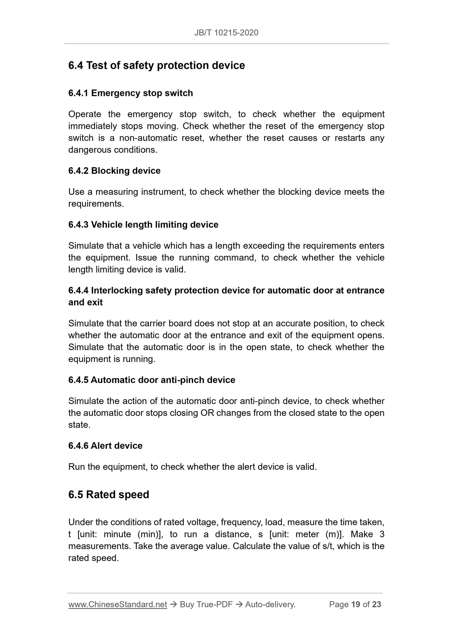
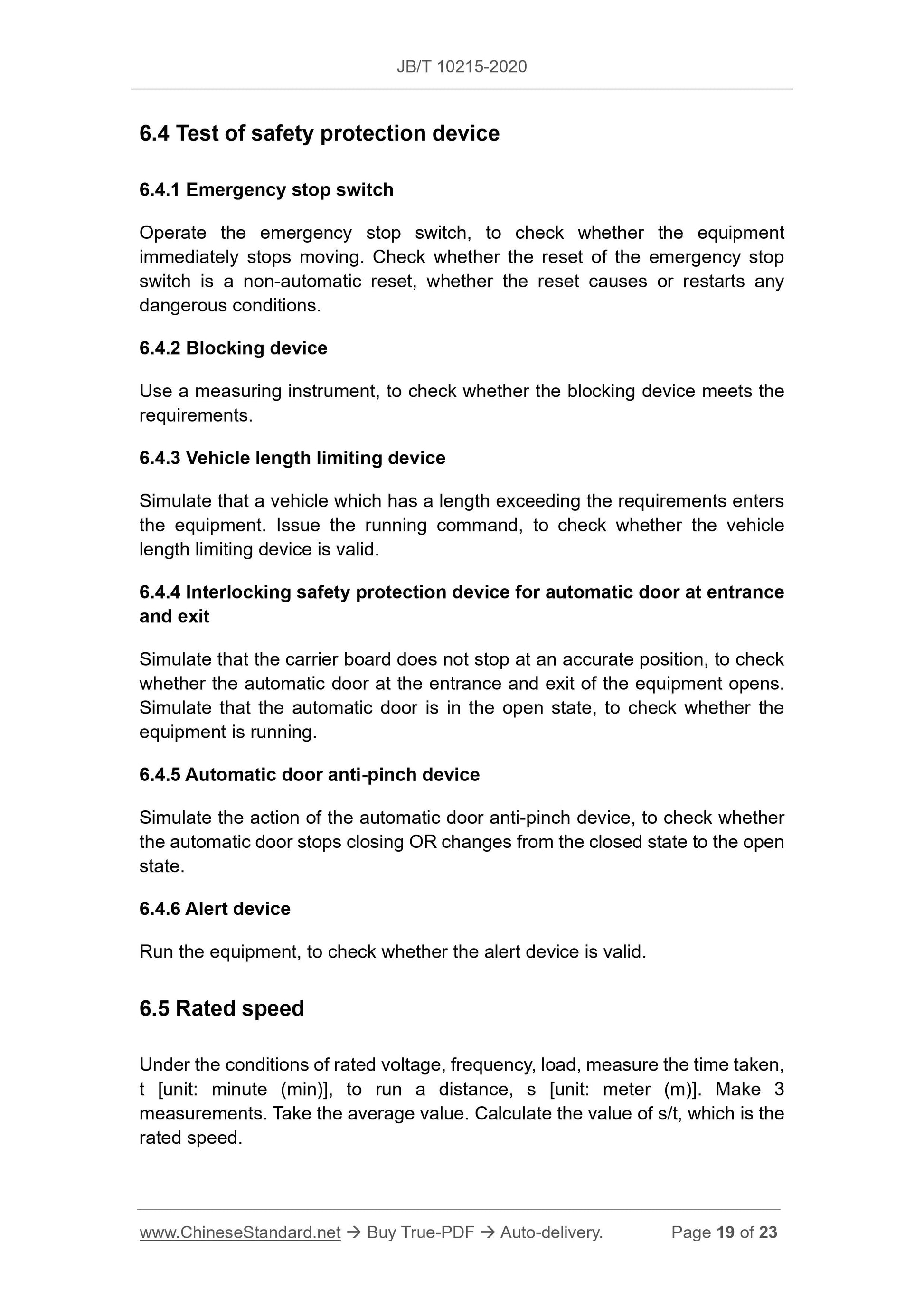
6.4 Test of safety protection device
6.4.1 Emergency stop switch
Operate the emergency stop switch, to check whether the equipment
immediately stops moving. Check whether the reset of the emergency stop switch is a non-automatic reset, whether the reset causes or restarts any dangerous conditions.
6.4.2 Blocking device
Use a measuring instrument, to check whether the blocking device meets the requirements.
6.4.3 Vehicle length limiting device
Simulate that a vehicle which has a length exceeding the requirements enters the equipment. Issue the running command, to check whether the vehicle
length limiting device is valid.
6.4.4 Interlocking safety protection device for automatic door at entrance and exit
Simulate that the carrier board does not stop at an accurate position, to check whether the automatic door at the entrance and exit of the equipment opens. Simulate that the automatic door is in the open state, to check whether the equipment is running.
6.4.5 Automatic door anti-pinch device
Simulate the action of the automatic door anti-pinch device, to check whether the automatic door stops closing OR changes from the closed state to the open state.
6.4.6 Alert device
Run the equipment, to check whether the alert device is valid.
6.5 Rated speed
Under the conditions of rated voltage, frequency, load, measure the time taken, t [unit: minute (min)], to run a distance, s [unit: meter (m)]. Make 3
measurements. Take the average value. Calculate the value of s/t, which is the rated speed.
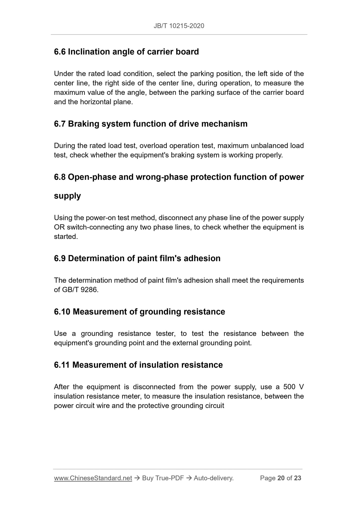
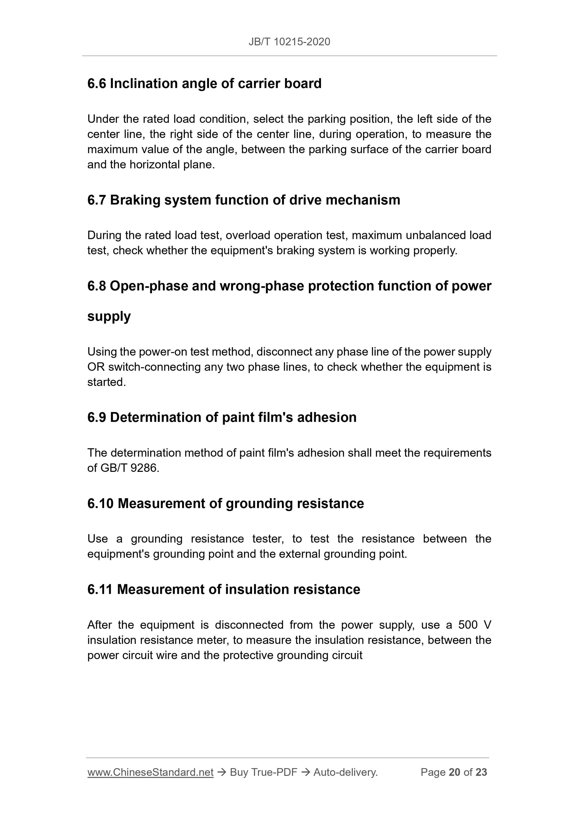
6.6 Inclination angle of carrier board
Under the rated load condition, select the parking position, the left side of the center line, the right side of the center line, during operation, to measure the maximum value of the angle, between the parking surface of the carrier board and the horizontal plane.
6.7 Braking system function of drive mechanism
During the rated load test, overload operation test, maximum unbalanced load test, check whether the equipment's braking system is working properly. 6.8 Open-phase and wrong-phase protection function of power
supply
Using the power-on test method, disconnect any phase line of the power supply OR switch-connecting any two phase lines, to check whether the equipment is started.
6.9 Determination of paint film's adhesion
The determination method of paint film's adhesion shall meet the requirements of GB/T 9286.
6.10 Measurement of grounding resistance
Use a grounding resistance tester, to test the resistance between the
equipment's grounding point and the external grounding point.
6.11 Measurement of insulation resistance
After the equipment is disconnected from the power supply, use a 500 V
insulation resistance meter, to measure the insulation resistance, between the power circuit wire and the protective grounding circuit

View full details