Skip to product information
1 of 7

PayPal, credit cards. Download editable-PDF and invoice in 1 second!

HJ/T 390-2007 English PDF (HJT390-2007)

HJ/T 390-2007 English PDF (HJT390-2007)

Regular price $310.00 USD
Regular price Sale price $310.00 USD
Sale Sold out
Shipping calculated at checkout.
Quotation: In 1-minute, 24-hr self-service. Click here HJ/T 390-2007 to get it for Purchase Approval, Bank TT...

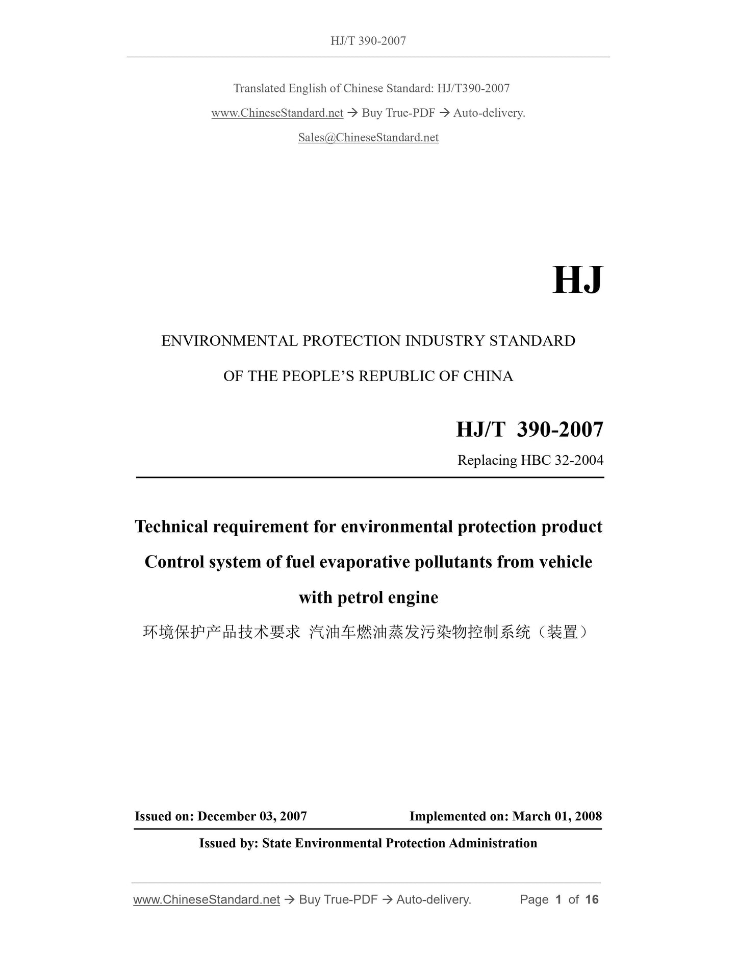
HJ/T 390-2007: Technical requirement for environmental labeling products. Control system of fuel evaporative pollutants from vehicle with petrol engine

This Standard specifies the definition, technical requirements, test methods, inspection rules and marking, packaging, transportation and storage requirements for the control system of fuel evaporative pollutants from vehicle with petrol engine. This Standard applies to the control system of fuel evaporative pollutants from vehicle with petrol engine (hereinafter referred to as control system).
HJ/T 390-2007
HJ
ENVIRONMENTAL PROTECTION INDUSTRY STANDARD
OF THE PEOPLE’S REPUBLIC OF CHINA
Replacing HBC 32-2004
Technical requirement for environmental protection product
Control system of fuel evaporative pollutants from vehicle
with petrol engine
ISSUED ON: DECEMBER 03, 2007
IMPLEMENTED ON: MARCH 01, 2008
Issued by: State Environmental Protection Administration
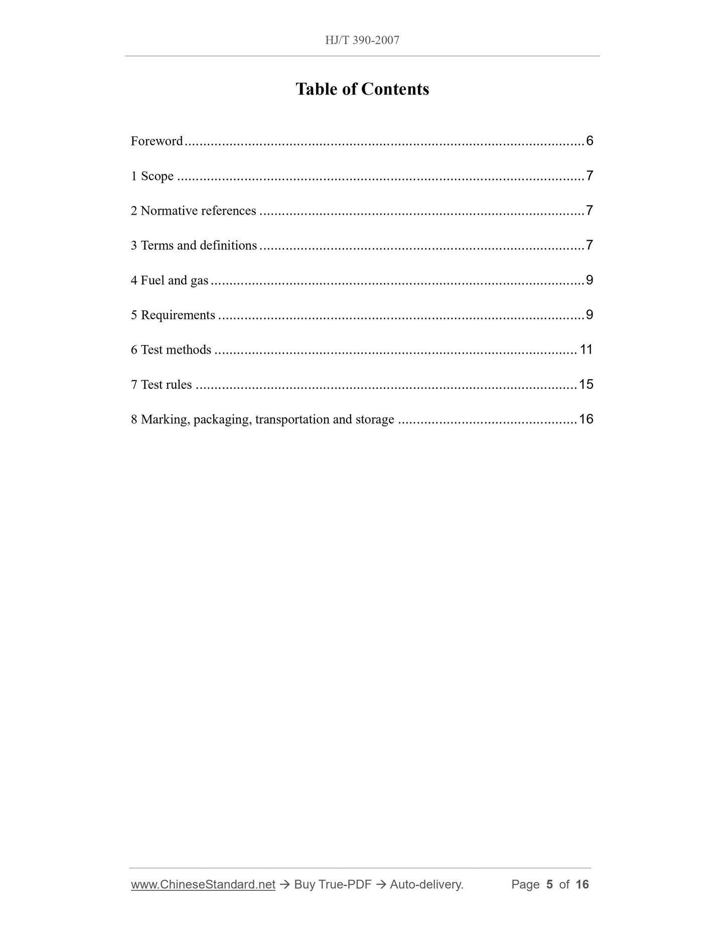
Table of Contents
Foreword ... 6
1 Scope ... 7
2 Normative references ... 7
3 Terms and definitions ... 7
4 Fuel and gas ... 9
5 Requirements ... 9
6 Test methods ... 11
7 Test rules ... 15
8 Marking, packaging, transportation and storage ... 16
Technical requirement for environmental protection product
Control system of fuel evaporative pollutants from vehicle
with petrol engine
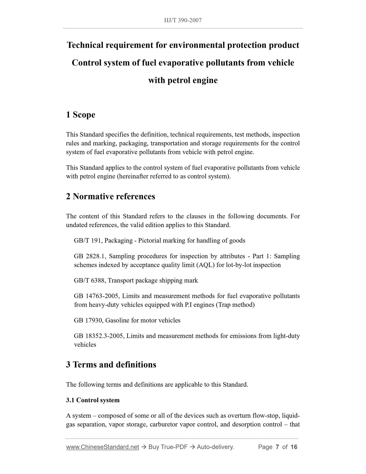
1 Scope
This Standard specifies the definition, technical requirements, test methods, inspection rules and marking, packaging, transportation and storage requirements for the control system of fuel evaporative pollutants from vehicle with petrol engine.
This Standard applies to the control system of fuel evaporative pollutants from vehicle with petrol engine (hereinafter referred to as control system).
2 Normative references
The content of this Standard refers to the clauses in the following documents. For undated references, the valid edition applies to this Standard.
GB/T 191, Packaging - Pictorial marking for handling of goods
GB 2828.1, Sampling procedures for inspection by attributes - Part 1: Sampling schemes indexed by acceptance quality limit (AQL) for lot-by-lot inspection GB/T 6388, Transport package shipping mark
GB 14763-2005, Limits and measurement methods for fuel evaporative pollutants from heavy-duty vehicles equipped with P.I engines (Trap method)
GB 17930, Gasoline for motor vehicles
GB 18352.3-2005, Limits and measurement methods for emissions from light-duty vehicles
3 Terms and definitions
The following terms and definitions are applicable to this Standard.
3.1 Control system
A system – composed of some or all of the devices such as overturn flow-stop, liquid- gas separation, vapor storage, carburetor vapor control, and desorption control – that uses activated carbon as adsorbent to control the emission of fuel evaporative pollutants from vehicle with petrol engine.
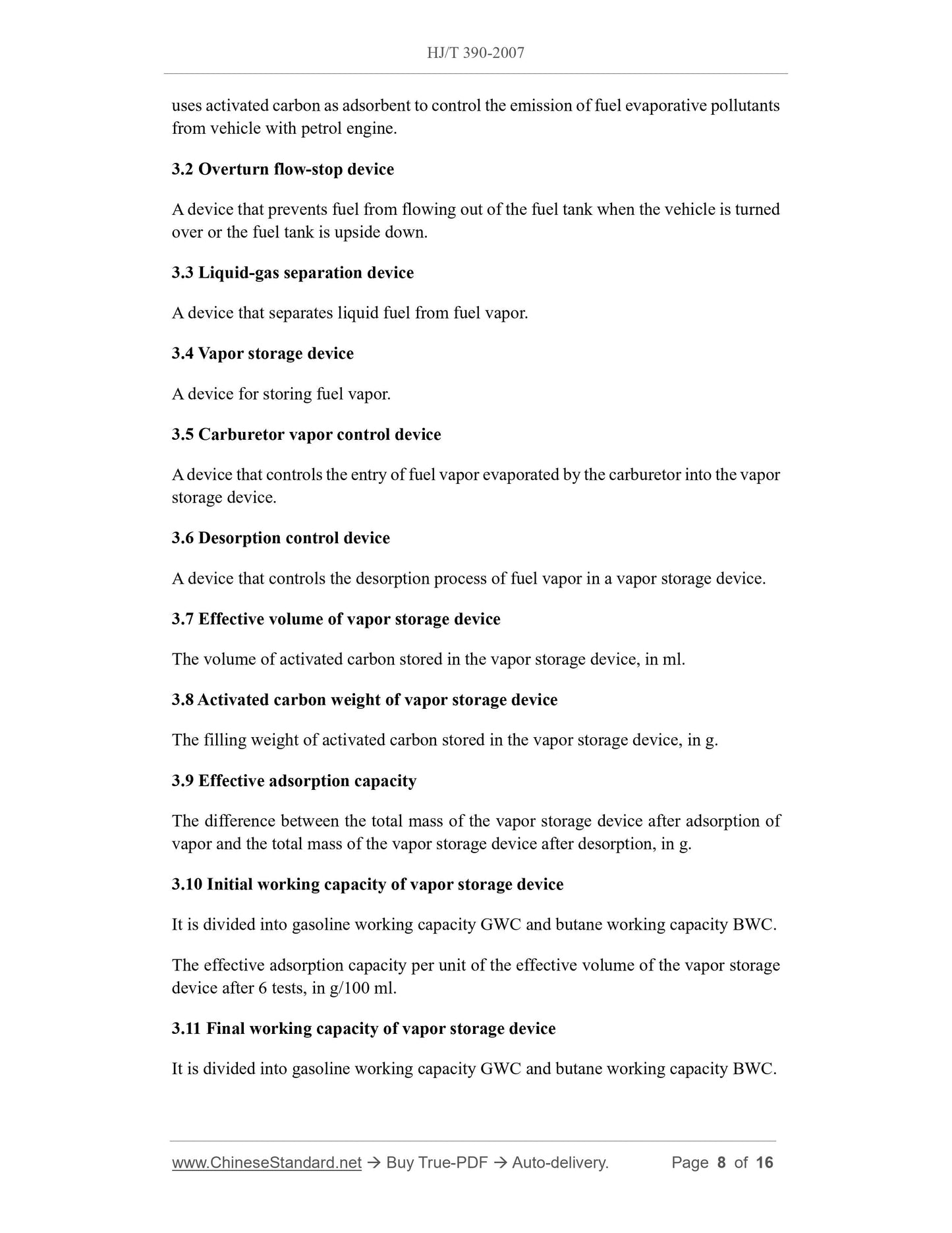
3.2 Overturn flow-stop device
A device that prevents fuel from flowing out of the fuel tank when the vehicle is turned over or the fuel tank is upside down.
3.3 Liquid-gas separation device
A device that separates liquid fuel from fuel vapor.
3.4 Vapor storage device
A device for storing fuel vapor.
3.5 Carburetor vapor control device
A device that controls the entry of fuel vapor evaporated by the carburetor into the vapor storage device.
3.6 Desorption control device
A device that controls the desorption process of fuel vapor in a vapor storage device. 3.7 Effective volume of vapor storage device
The volume of activated carbon stored in the vapor storage device, in ml. 3.8 Activated carbon weight of vapor storage device
The filling weight of activated carbon stored in the vapor storage device, in g. 3.9 Effective adsorption capacity
The difference between the total mass of the vapor storage device after adsorption of vapor and the total mass of the vapor storage device after desorption, in g. 3.10 Initial working capacity of vapor storage device
It is divided into gasoline working capacity GWC and butane working capacity BWC. The effective adsorption capacity per unit of the effective volume of the vapor storage device after 6 tests, in g/100 ml.
3.11 Final working capacity of vapor storage device
It is divided into gasoline working capacity GWC and butane working capacity BWC. 5.2.1 Control system ventilation resistance performance
Carry out the test according to 6.2.1. The pressure difference shall be less than or equal to 0.98 kPa.
5.2.2 Control system sealing performance
Carry out the test according to 6.2.2. There shall be no leakage at each connection. 5.2.3 Overturn flow-stop device performance
Carry out the test according to 6.2.3. When the device is in the normal position, under the pressure of 20.0 kPa, the stable gas flow shall be greater than 7.0 L/min; when the device is overturned at a position of 180°, under the pressure of 5.0 kPa, the stable gas flow shall be less than 0.05 L/min.
5.2.4 Desorption control device performance
Carry out the test in accordance with 6.2.4. The desorption control device shall meet the requirements of the enterprise standard.
5.2.5 Initial working capacity of vapor storage device
Carry out the test in accordance with 6.2.5. Initial working capacity of the vapor storage device: GWC shall be greater than or equal to 6.5 g/100 ml; or BWC shall be greater than or equal to 7.0 g/100 ml.
5.2.6 Final working capacity of vapor storage device
Carry out the test in accordance with 6.2.5. Final working capacity of the vapor storage device: GWC shall be greater than or equal to 5.2 g/100 ml; or BWC shall be greater than or equal to 5.6 g/100 ml.
5.2.7 Vibration resistance
Carry out the test in accordance with 6.2.6. The parts shall not have obvious deformation, loose installation and connection parts, cracks, ruptures and other defects; the activated carbon powder falling out of all outlets of the steam storage device shall not exceed 1 g, and shall meet the requirements of 5.2.1 and 5.2.2.
5.2.8 Weather resistance
Carry out the test in accordance with 6.2.7. The parts shall not have dimensional changes that affect the service performance, as well as defects such as obvious deformation, corrugation, loose installation and connection parts, cracks, ruptures, peeling, swelling, release and whitening, and shall comply with the requirements of 5.2.2.
5.3 Performance requirements after assembly
5.3.1 Sealing performance
Carry out the test in accordance with 6.3.1. The pressure drop shall not exceed 0.49 kPa. 5.3.2 Ventilation performance
Carry out the test in accordance with 6.3.2. The pressure shall fall below 0.98 kPa. 5.3.3 Fuel evaporative emission performance
Carry out the test in accordance with 6.3.3. The evaporative emission shall comply with the provisions of GB 18352.3-2005 and GB 14763-2005.
6 Test methods
6.1 Laboratory ambient temperature
The laboratory ambient temperature is 25 °C ± 5 °C.
6.2 Control system and component performance test method
6.2.1 Control system ventilation resistance performance
Air flows in from the adsorption port of the vapor storage device and flows out from the air vent of the vapor storage device, and the desorption port is blocked. When the flow rate is stable at 10 L/min, measure the pressure difference between the adsorption port and the air vent.
6.2.2 Control system sealing performance
Place the control system in clean water with a depth of not more than 100 mm; inlet compressed air with a pressure of 14.0 kPa and keep it for 30 s; check whether there are air bubbles at each connection. The generation of air bubbles is regarded as a leak. 6.2.3 Overturn flow-stop device performance
Connect the flowmeter in series with the overturn flow-stop device and place it vertically. When the device is in the normal position, inlet the compressed air with the pressure of 20.0 kPa from top to bottom; measure the stable gas flow. When the device is overturned at a position of 180°, inlet the compressed air with the pressure of 5.0 kPa from top to bottom; measure the stable gas flow.
6.2.4 Desorption control device performance
Connect the desorption control device to the vehicle, and connect a flow meter in series between the desorption control device and the engine. Measure stable gas flow under conditions required by corporate standards.
e) Use dry air at a temperature of (25 ± 5) °C to desorb the vapor storage device. The desorption flow rate is (25±1) L/min, and the amount of desorbed gas is 600 effective volumes of the vapor storage device (if the maximum desorption flow rate of the vapor storage device is less than (25±1) L/min, use the maximum desorption flow rate);
f) Weigh the vapor storage device;
g) Drain the gasoline in the vapor generating device as shown in Figure 2; h) Repeat steps b) to g) 150 times, wherein steps d) and f) from the 7th cycle to the 148th cycle can be omitted;
i) Calculate the average value of the difference in the mass of the vapor storage device measured in steps d) and f) in the 5th and 6th cycles;
j) The ratio of average value obtained in step i) to the effective volume of the vapor storage device is the initial working capacity of the device;
k) Calculate the average value of the difference in the mass of the vapor storage device measured in steps d) and f) in the 149th and 150th cycles;
l) The ratio of average value obtained in step k) to the effective volume of the vapor storage device is the final working capacity of the device.
6.2.5.2 Use butane for testing
a) Weigh the vapor storage device;
b) Use a mixture of 50% by volume of butane and 50% by volume of nitrogen; at a butane inflation rate of 2.5 g/min, absorb the vapor storage device under the condition of (25 ± 5°C) until the critical point;
c) Weigh the vapor storage device;
d) Use dry air at a temperature of (25 ± 5) °C to desorb the vapor storage device. The desorption flow rate is (25 ± 1) L/min, and the amount of desorbed gas is 600 effective volumes of the vapor storage device [if the maximum desorption flow rate of the vapor storage device is less than (25±1) L/min, use the maximum desorption flow rate];
e) Weigh the vapor storage device;
f) Repeat steps b) to e) 150 times, wherein steps c) and e) from the 7th cycle to the 148th cycle can be omitted;
g) Calculate the average value of the difference in the mass of the vapor storage device measured in steps c) and e) in the 5th and 6th cycles;

View full details