HJ 870-2017 English PDF (HJ870-2017)
Regular price
$125.00 USD
Regular price
Sale price
$125.00 USD
Unit price
/
per
Delivery: 3 seconds. Download true-PDF + Invoice.
Get QUOTATION in 1-minute: Click HJ 870-2017
Historical versions: HJ 870-2017
Preview True-PDF (Reload/Scroll if blank)
HJ 870-2017: Stationary source emission. Determination of carbon dioxide. Non-dispersive infrared absorption method
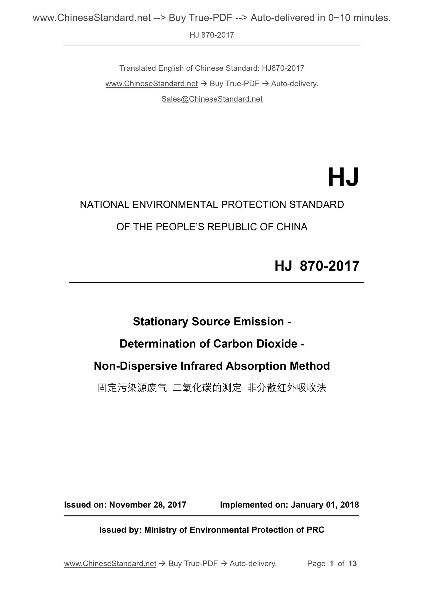
HJ 870-2017
HJ
NATIONAL ENVIRONMENTAL PROTECTION STANDARD
OF THE PEOPLE’S REPUBLIC OF CHINA
Stationary Source Emission -
Determination of Carbon Dioxide -
Non-Dispersive Infrared Absorption Method
ISSUED ON: NOVEMBER 28, 2017
IMPLEMENTED ON: JANUARY 01, 2018
Issued by: Ministry of Environmental Protection of PRC
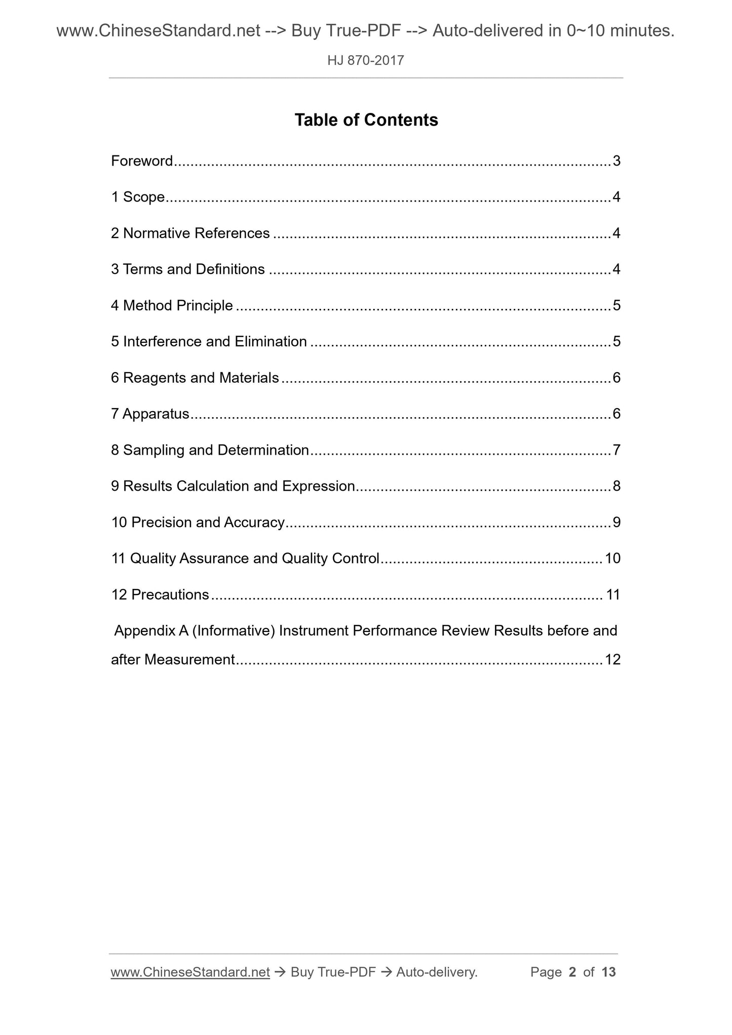
Table of Contents
Foreword ... 3
1 Scope ... 4
2 Normative References ... 4
3 Terms and Definitions ... 4
4 Method Principle ... 5
5 Interference and Elimination ... 5
6 Reagents and Materials ... 6
7 Apparatus ... 6
8 Sampling and Determination ... 7
9 Results Calculation and Expression... 8
10 Precision and Accuracy ... 9
11 Quality Assurance and Quality Control ... 10
12 Precautions ... 11
Appendix A (Informative) Instrument Performance Review Results before and
after Measurement ... 12
Stationary Source Emission -
Determination of Carbon Dioxide -
Non-Dispersive Infrared Absorption Method
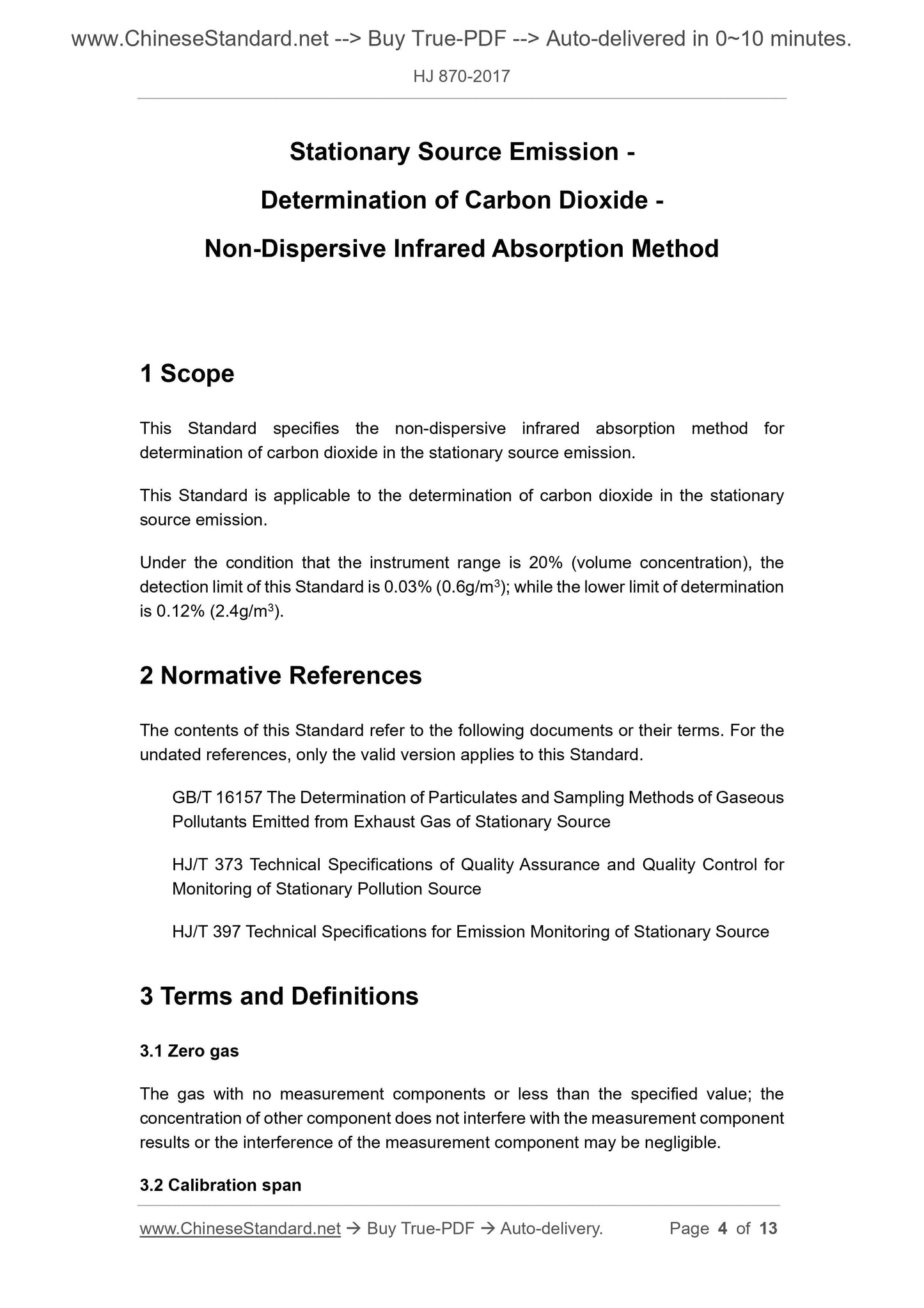
1 Scope
This Standard specifies the non-dispersive infrared absorption method for
determination of carbon dioxide in the stationary source emission.
This Standard is applicable to the determination of carbon dioxide in the stationary
source emission.
Under the condition that the instrument range is 20% (volume concentration), the
detection limit of this Standard is 0.03% (0.6g/m3); while the lower limit of determination
is 0.12% (2.4g/m3).
2 Normative References
The contents of this Standard refer to the following documents or their terms. For the
undated references, only the valid version applies to this Standard.
GB/T 16157 The Determination of Particulates and Sampling Methods of Gaseous
Pollutants Emitted from Exhaust Gas of Stationary Source
HJ/T 373 Technical Specifications of Quality Assurance and Quality Control for
Monitoring of Stationary Pollution Source
HJ/T 397 Technical Specifications for Emission Monitoring of Stationary Source
3 Terms and Definitions
3.1 Zero gas
The gas with no measurement components or less than the specified value; the
concentration of other component does not interfere with the measurement component
results or the interference of the measurement component may be negligible.
3.2 Calibration span
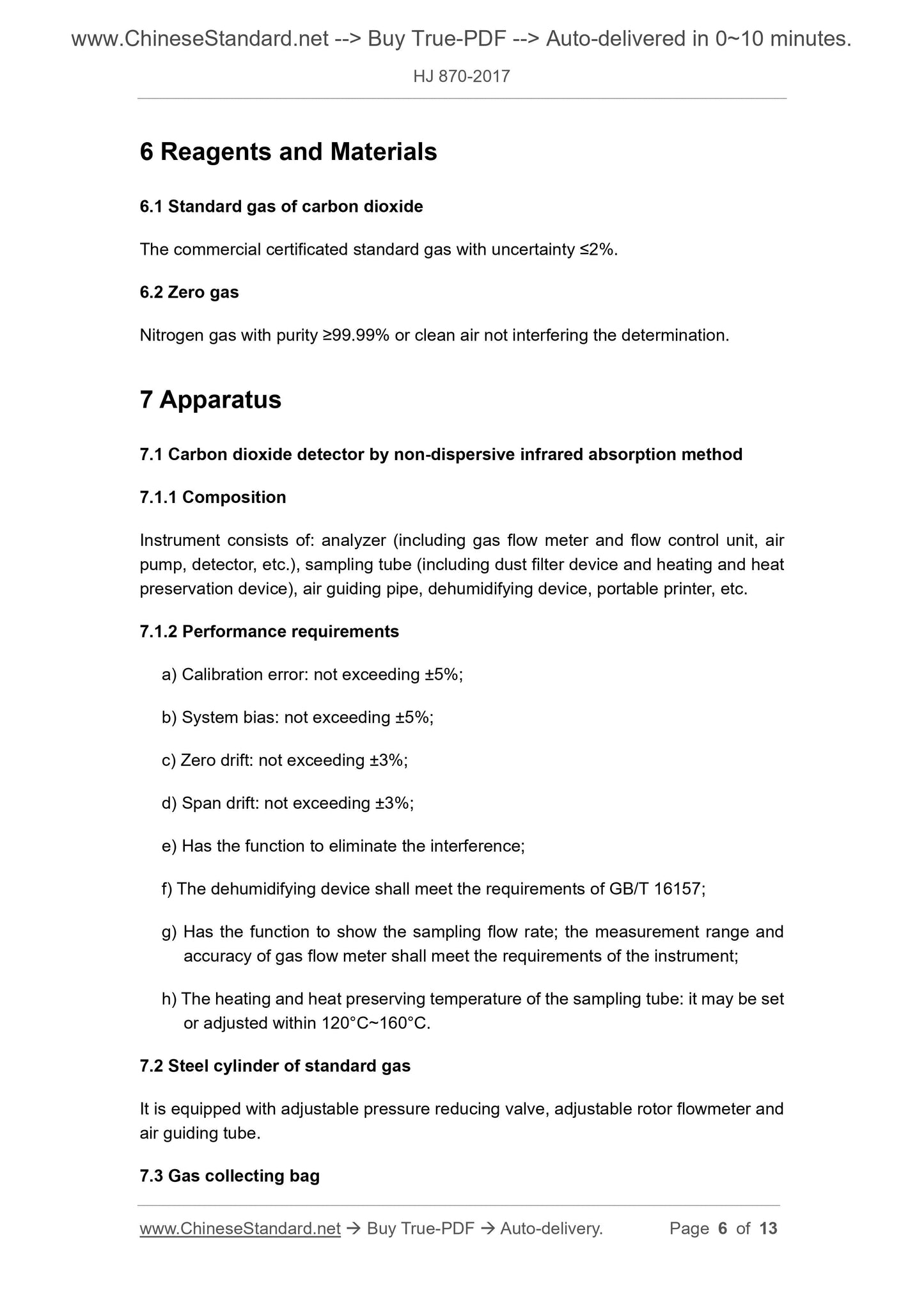
6 Reagents and Materials
6.1 Standard gas of carbon dioxide
The commercial certificated standard gas with uncertainty ≤2%.
6.2 Zero gas
Nitrogen gas with purity ≥99.99% or clean air not interfering the determination.
7 Apparatus
7.1 Carbon dioxide detector by non-dispersive infrared absorption method
7.1.1 Composition
Instrument consists of: analyzer (including gas flow meter and flow control unit, air
pump, detector, etc.), sampling tube (including dust filter device and heating and heat
preservation device), air guiding pipe, dehumidifying device, portable printer, etc.
7.1.2 Performance requirements
a) Calibration error: not exceeding ±5%;
b) System bias: not exceeding ±5%;
c) Zero drift: not exceeding ±3%;
d) Span drift: not exceeding ±3%;
e) Has the function to eliminate the interference;
f) The dehumidifying device shall meet the requirements of GB/T 16157;
g) Has the function to show the sampling flow rate; the measurement range and
accuracy of gas flow meter shall meet the requirements of the instrument;
h) The heating and heat preserving temperature of the sampling tube: it may be set
or adjusted within 120°C~160°C.
7.2 Steel cylinder of standard gas
It is equipped with adjustable pressure reducing valve, adjustable rotor flowmeter and
air guiding tube.
7.3 Gas collecting bag
8.5 Sample determination
8.5.1 Place the front end of the sampling tube of the instrument in the exhaust pipe;
block the sampling hole, so that it does not leak gas.
8.5.2 Start the air pump; conduct sampling determination according to the sampling
flow specified by the detector. After the detector is stable, save the measurement data
in minutes; take the average value of the measure data for at least continuous 5
minutes as the one measurement value.
8.5.3 After the end of one measurement, use the zero gas to clean the instrument
according to the instruction manual of the instrument.
8.5.4 After obtaining the measurement result, use zero gas to clean the instrument.
When the indication value returns to near zero point, turn off the power and finish the
measurement.
9 Results Calculation and Expression
9.1 Results calculation
9.1.1 Calculation of exhaust flow rate
According to the provisions of GB/T 16157, calculate the dry exhaust flow rate Qsn
(m3/h) under the standard state (273K, 101.325kPa).
9.1.2 Calculation of carbon dioxide concentration
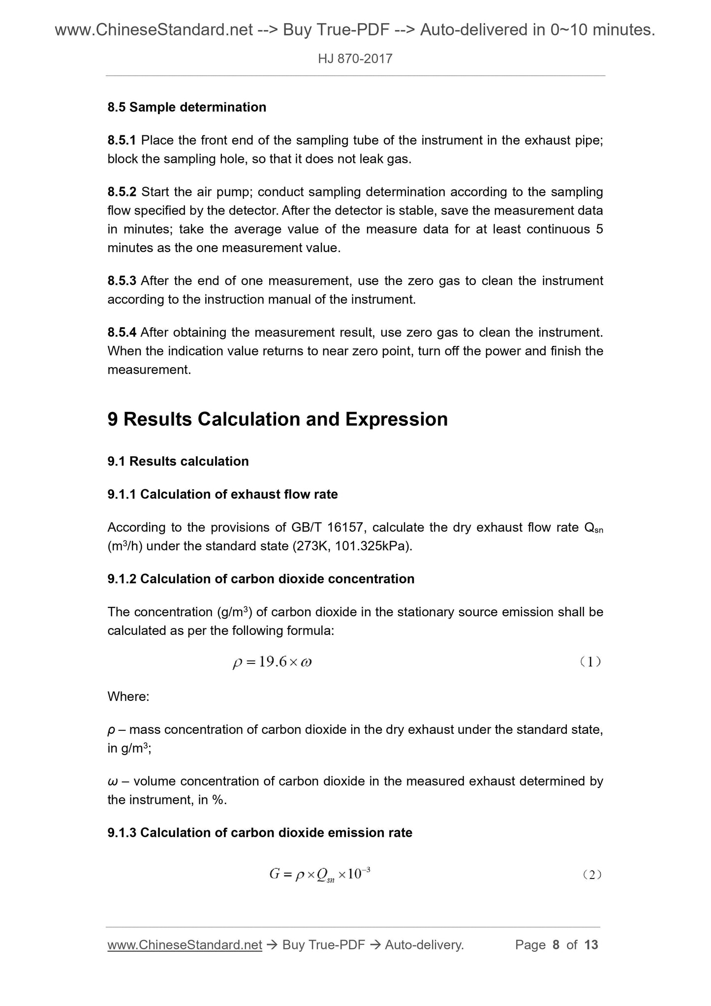
The concentration (g/m3) of carbon dioxide in the stationary source emission shall be
calculated as per the following formula:
Where:
ρ – mass concentration of carbon dioxide in the dry exhaust under the standard state,
in g/m3;
ω – volume concentration of carbon dioxide in the measured exhaust determined by
the instrument, in %.
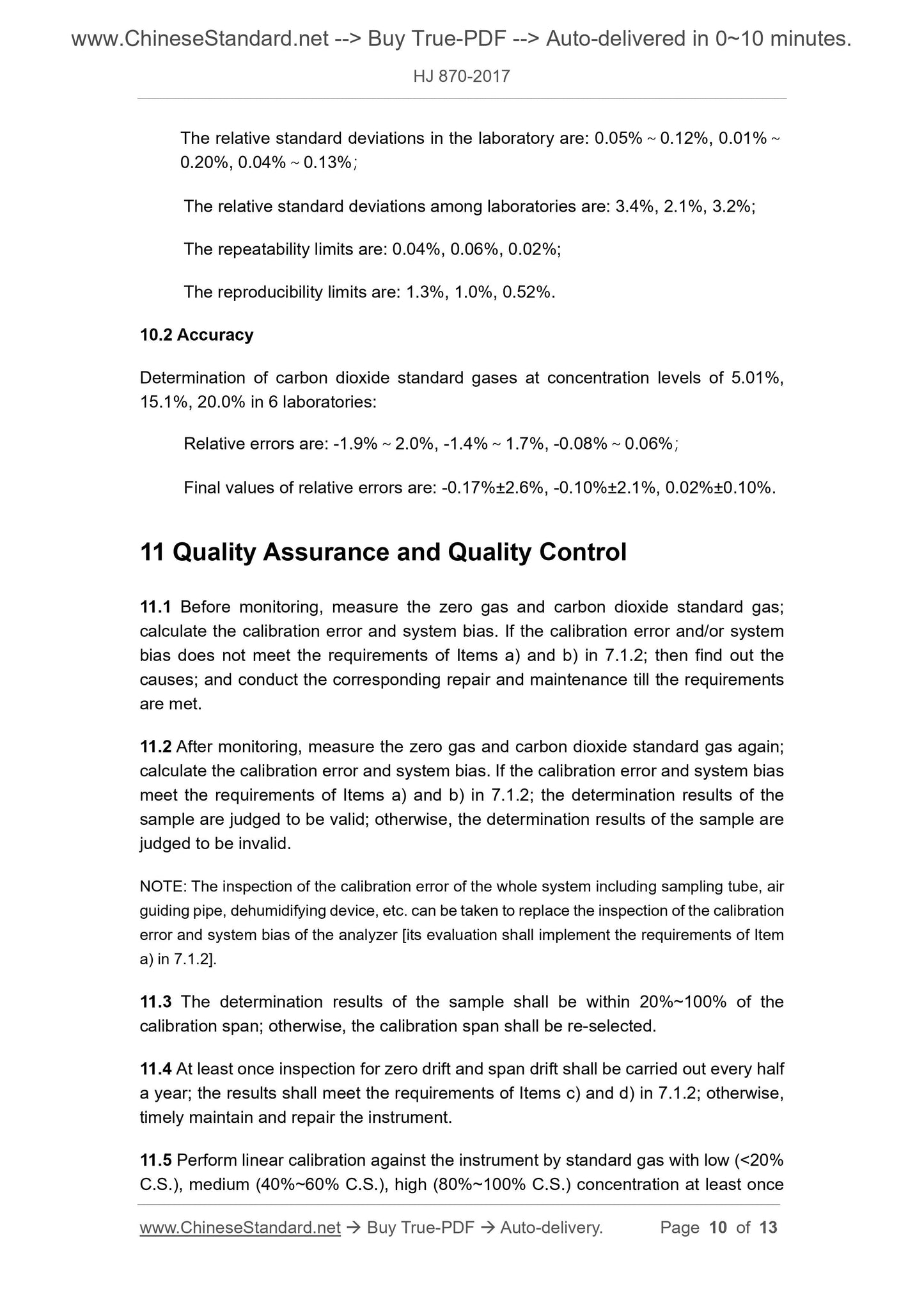
9.1.3 Calculation of carbon dioxide emission rate
The relative standard deviations in the laboratory are: 0.05%~0.12%, 0.01%~
0.20%, 0.04%~0.13%;
The relative standard deviations among laboratories are: 3.4%, 2.1%, 3.2%;
The repeatability limits are: 0.04%, 0.06%, 0.02%;
The reproducibility limits are: 1.3%, 1.0%, 0.52%.
10.2 Accuracy
Determination of carbon dioxide standard gases at concentration levels of 5.01%,
15.1%, 20.0% in 6 laboratories:
Relative errors are: -1.9%~2.0%, -1.4%~1.7%, -0.08%~0.06%;
Final values of relative errors are: -0.17%±2.6%, -0.10%±2.1%, 0.02%±0.10%.
11 Quality Assurance and Quality Control
11.1 Before monitoring, measure the zero gas and carbon dioxide standard gas;
calculate the calibration error and system bias. If the calibration error and/or system
bias does not meet the requirements of Items a) and b) in 7.1.2; then find out the
causes; and conduct the corresponding repair and maintenance till the requirements
are met.
11.2 After monitoring, measure the zero gas and carbon dioxide standard gas again;
calculate the calibration error and system bias. If the calibration error and system bias
meet the requirements of Items a) and b) in 7.1.2; the determination results of the
sample are judged to be valid; otherwise, the determination results of the sample are
judged to be invalid.
NOTE: The inspection of the calibration error of the whole system including sampling tube, air
guiding pipe, dehumidifying device, etc. can be taken to replace the inspection of the calibration
error and system bias of the analyzer [its evaluation shall implement the requirements of Item
a) in 7.1.2].
11.3 The determination results of the sample shall be within 20%~100% of the
calibration span; otherwise, the calibration span shall be re-selected.
11.4 At least once inspection for zero drift and span drift shall be carried out every half
a year; the results shall meet the requirements of Items c) and d) in 7.1.2; otherwise,
timely maintain and repair the instrument.
11.5 Perform linear calibration against the instrument by standard gas with low (< 20%
C.S.), medium (40%~60% C.S.), high (80%~100% C.S.) concentration at least once