1
/
of
7
www.ChineseStandard.us -- Field Test Asia Pte. Ltd.
HG/T 20513-2014 English PDF (HG/T20513-2014)
HG/T 20513-2014 English PDF (HG/T20513-2014)
Regular price
$620.00
Regular price
Sale price
$620.00
Unit price
/
per
Shipping calculated at checkout.
Couldn't load pickup availability
HG/T 20513-2014: Design code of instrument grounding
Delivery: 9 seconds. Download (and Email) true-PDF + Invoice.Get Quotation: Click HG/T 20513-2014 (Self-service in 1-minute)
Newer / historical versions: HG/T 20513-2014
Preview True-PDF
Scope
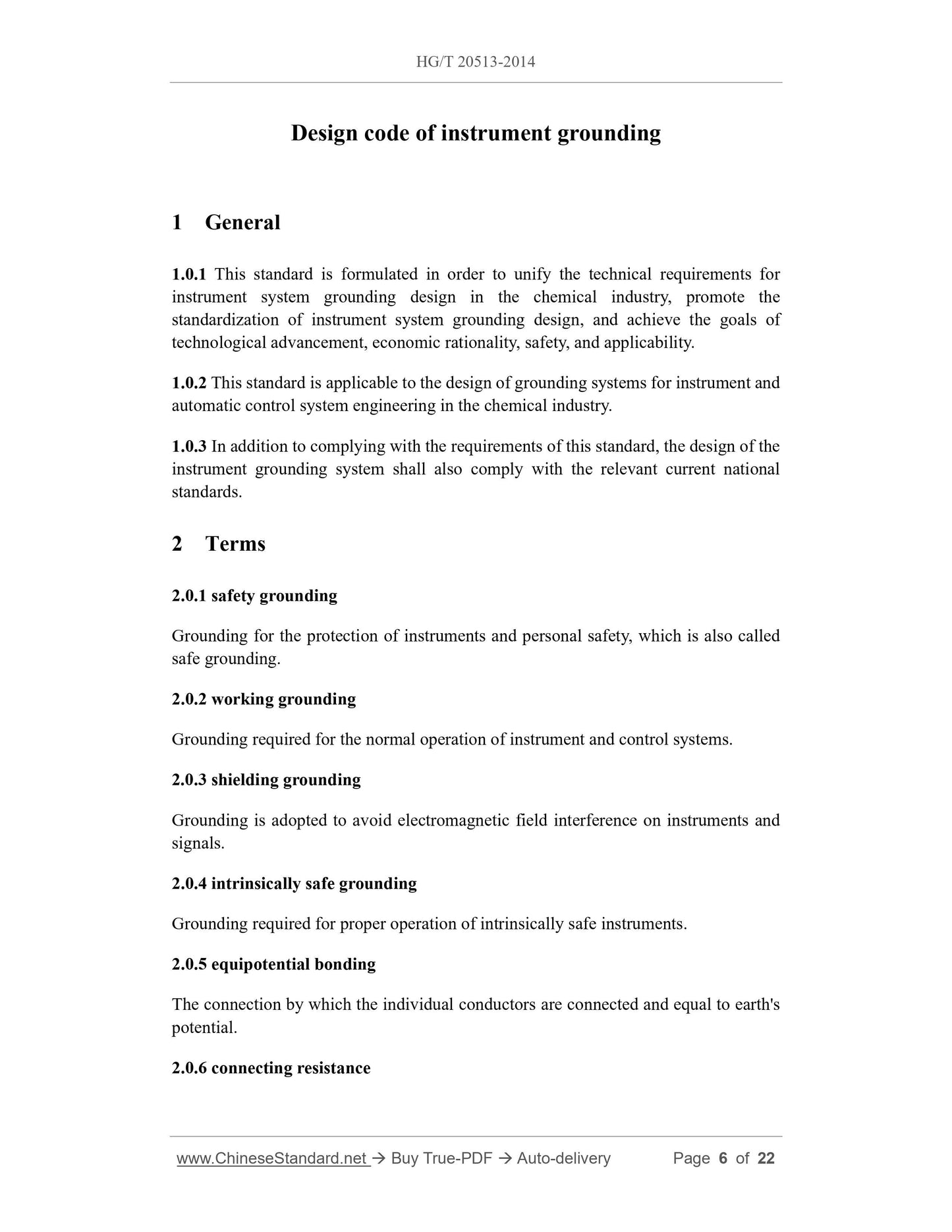
1.0.1 This standard is formulated in order to unify the technical requirements forinstrument system grounding design in the chemical industry, promote the
standardization of instrument system grounding design, and achieve the goals of
technological advancement, economic rationality, safety, and applicability.
1.0.2 This standard is applicable to the design of grounding systems for instrument and
automatic control system engineering in the chemical industry.
1.0.3 In addition to complying with the requirements of this standard, the design of the
instrument grounding system shall also comply with the relevant current national
standards.
Basic Data
| Standard ID | HG/T 20513-2014 (HG/T20513-2014) |
| Description (Translated English) | Design code of instrument grounding |
| Sector / Industry | Chemical Industry Standard (Recommended) |
| Classification of Chinese Standard | P72 |
| Classification of International Standard | 71.010 |
| Word Count Estimation | 28,211 |
| Date of Issue | 5/6/2014 |
| Date of Implementation | 10/1/2014 |
| Older Standard (superseded by this standard) | HG/T 20513-2000 |
| Regulation (derived from) | Ministry of Industry and Information Technology - Announcement 2014 No 32. |
| Issuing agency(ies) | Ministry of Industry and Information Technology |
| Summary | This standard specifies the instrumentation and control systems to protect ground; grounding; grounding system and grounding principles; grounding connection method; join the resistance, resistance to ground and ground resistance; grounding connection spe |
Share