Skip to product information
1 of 6

PayPal, credit cards. Download editable-PDF and invoice in 1 second!

GB/T 8358-2023 English PDF (GBT8358-2023)

GB/T 8358-2023 English PDF (GBT8358-2023)

Regular price $200.00 USD
Regular price Sale price $200.00 USD
Sale Sold out
Shipping calculated at checkout.
Delivery: 3 seconds. Download true-PDF + Invoice.
Get QUOTATION in 1-minute: Click GB/T 8358-2023
Historical versions: GB/T 8358-2023
Preview True-PDF (Reload/Scroll if blank)

GB/T 8358-2023: Steel wire ropes -- Determination of breaking force
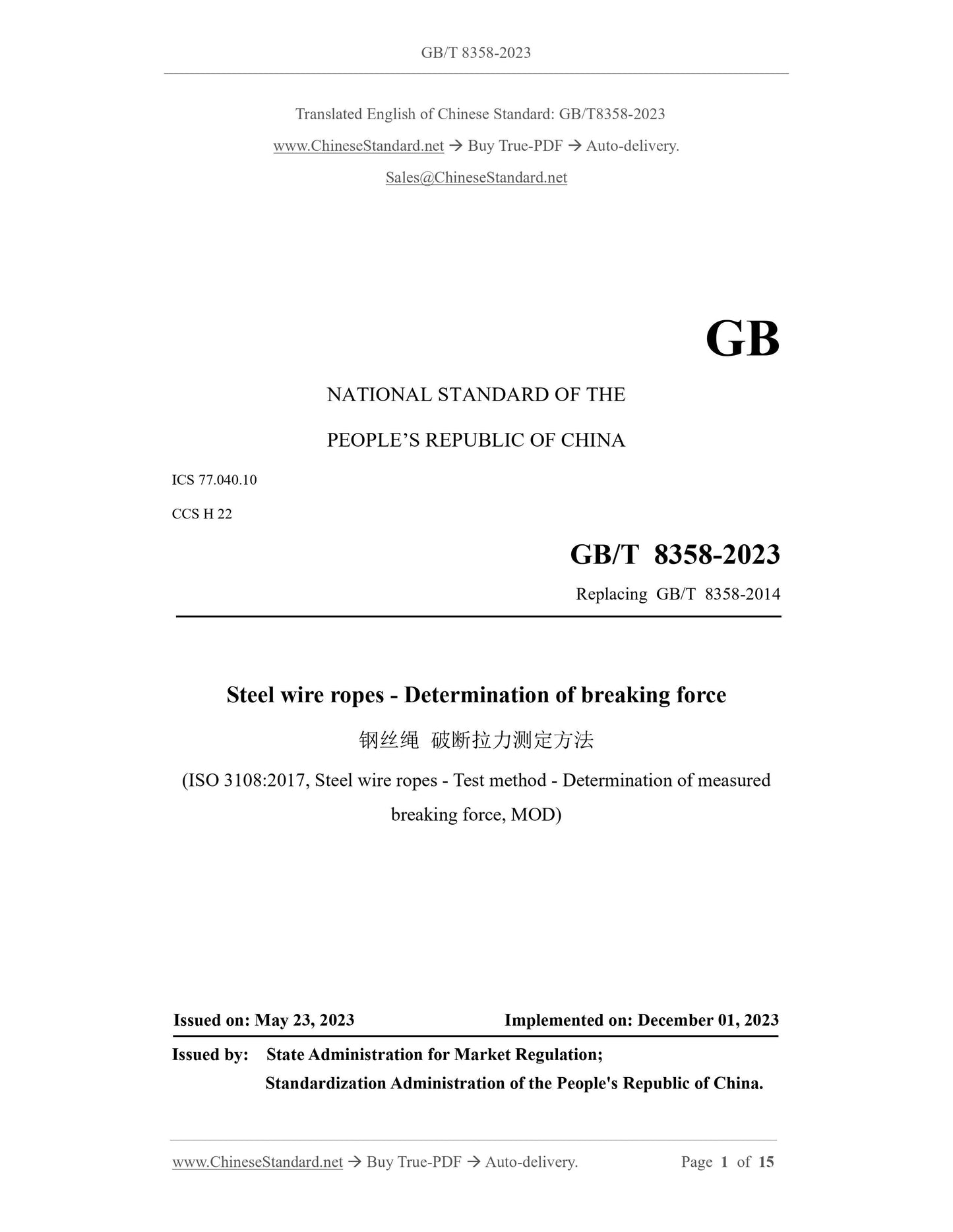
GB/T 8358-2023
GB
NATIONAL STANDARD OF THE
PEOPLE’S REPUBLIC OF CHINA
ICS 77.040.10
CCS H 22
Replacing GB/T 8358-2014
Steel wire ropes - Determination of breaking force
(ISO 3108:2017, Steel wire ropes - Test method - Determination of measured
breaking force, MOD)
ISSUED ON: MAY 23, 2023
IMPLEMENTED ON: DECEMBER 01, 2023
Issued by: State Administration for Market Regulation;
Standardization Administration of the People's Republic of China.
Table of Contents
Foreword ... 3
1 Scope ... 6
2 Normative references ... 6
3 Terms and definitions ... 6
4 Principle ... 8
5 Specimen preparation ... 8
6 Test equipment ... 11
7 Test procedures ... 11
8 Test report ... 12
Annex A (informative) Method of grouting material pouring ... 13
Bibliography ... 15
Steel wire ropes - Determination of breaking force
1 Scope
This document specifies the principles, specimen preparation, test equipment, test
procedures, and test reports for the method to determine the breaking tensile force of
steel wire ropes.
This document is applicable to the determination of breaking force of various wire rope
products.
2 Normative references
The following referenced documents are indispensable for the application of this
document. For dated references, only the edition cited applies. For undated references,
the latest edition of the referenced document (including any amendments) applies.
GB/T 8706, Steel wire ropes -- Vocabulary, designation and classification (GB/T
8706-2017, ISO 17893:2004, MOD)
GB/T 16825.1, Metallic materials -- Calibration and verification of static uniaxial
testing machines -- Part 1: Tension/compression testing machines -- Calibration and
verification of the force-measuring system (GB/T 16825.1-2008, ISO 7500-1:2004,
IDT)
GB/T 30588, Terminations for steel wire ropes -- Molten metal socketing
YB/T 4615, Steel rope end resin socket
JJG 139, Verification regulation of Tension, Compression and Universal Testing
Machines
JJG 475, Verification Regulation of Electronic Universal Testing Machine
JJG 1063, Verification Regulation of Electro-hydraulic Servo Universal Testing
Machines
3 Terms and definitions
For the purposes of this document, the terms and definitions defined in GB/T 8706 as
well as the followings apply.
A specimen installation method is to clamp the specimen directly into the appropriate
jaws of the tensile testing machine for tensile testing.
3.9 method of wrapping
A specimen installation method that is to directly wrap the specimen in the rope groove
of the winding test wheel for tensile testing.
4 Principle
Apply tensile force to the wire rope specimen. Stretch until the wire rope breaks.
Determine the breaking tension of the wire rope, or stretch it to the specified tension
value.
5 Specimen preparation
5.1 General requirements
5.1.1 The wire rope specimen can be intercepted by grinding wheel cutting, pressure
cutting or shear cutting. The specimen taken shall avoid the molten part at the end of
the wire rope.
5.1.2 In order to prevent the wire rope from loosening and the geometric position of the
strands and wires from changing, sufficient loosening or clamping length shall be
reserved at both ends before intercepting the specimen. Tie firmly with low carbon steel
wire.
5.1.3 For unused wire ropes, test specimens shall be taken from the wire ropes that are
not damaged during visual inspection. The intercepted wire rope specimen shall be
straight. There shall be no bending or damage.
5.1.4 For used wire ropes, test specimens shall be taken from the wire ropes confirmed
by the relevant parties.
5.1.5 The minimum effective test section length (that is, the distance between the two
chucks) shall comply with the requirements in Table 1.
NOTE: For thick-diameter wire ropes, the minimum test section length is generally 6 times the wire
rope pitch.
5.1.6 The total length of the specimen is equal to the length of the test section plus the
clamping length at both ends of the specimen.
1 - Jaw seat;
2 - Clamping block;
3 - Specimen;
4 - Packing;
d - Nominal diameter of wire rope;
L - Minimum effective test section length.
Figure 2 -- Schematic diagram of specimen using method of direct gripping
5.5 Method of wrapping
5.5.1 The winding test wheel shall be selected to match the diameter of the wire rope.
The ratio of the diameter of the winding test wheel to the diameter of the wire rope shall
not be less than 16.
5.5.2 The diameter of the rope groove around the test wheel shall be controlled within
the range of 1.06 to 1.10 times the nominal diameter of the wire rope.
5.5.3 The method of wrapping is suitable for wire ropes with a diameter not larger than
20 mm.
6 Test equipment
6.1 This test can be performed on any tensile testing machine that meets the
requirements of this document.
6.2 The force measuring system of the testing machine shall comply with the
requirements of GB/T 16825.1. Calibrate in accordance with JJG 139, JJG 475 or JJG
1063. Its accuracy shall be grade 1 or better.
6.3 The testing machine shall be equipped with safety protection devices to prevent
wires from flying out and injuring people during the test.
7 Test procedures
7.1 Unless otherwise specified, the test is generally conducted at room temperature
within the range of 10℃~35℃. For tests with strict temperature requirements, the test
temperature shall be 23℃±5℃.
7.2 Mount the specimen on the tensile testing machine. Ensure that the axis of the
specimen coincides with the axis of the chuck of the testing machine.
7.3 For tensile specimens produced by method of alloy poured socketing or method of
resin pouring, when testing with a vertical tensile testing machine, first place the
specimen in the upper and lower jaw seats. Let the specimen in the lower jaw seat hang
Annex A
(informative)
Method of grouting material pouring
A.1 Cement-based grouting material
Cement-based grouting materials are made of raw materials such as cement, aggregates,
admixtures and mineral admixtures, which are measured and mixed in proportions in
professional chemical plants. Add water or mix the supporting components according
to the specified proportion at the place of use. Use it for bolt anchoring, structural
reinforcement, prestressed tunnels, etc.
The grouting material used shall comply with the requirements of GB/T 50488.
A.2 Method of grouting material pouring
A.2.1 The mold used for pouring shall be easy to disassemble. The inner surface in
contact with the grouting material shall be smooth and clean.
A.2.2 The bundling, end breaking, and surface cleaning of the specimens shall comply
with the requirements of 5.2.4.
A.2.3 Place the cleaned broom head into the mold and adjust it. Pour the mixed grouting
material into the mold. Use a thin steel rod to pound continuously to remove the air
from the pouring body until it is filled. Then place the poured specimen at room
temperature for 3h to 4 h before demoulding. Figure 1 is a schematic diagram of the
sample prepared using this method.
A.3 Maintenance
A.3.1 After demoulding, the specimens are placed in a high-temperature steam curing
box for steam curing. The heating rate shall not be greater than 12℃/h. After the
temperature is raised to 80°C, the constant temperature (80°C±5°C) is maintained for
more than 48 h until the compressive strength of the specimen cured under the same
View full details