1
/
of
5
www.ChineseStandard.us -- Field Test Asia Pte. Ltd.
GB/T 7736-2008 English PDF (GB/T7736-2008)
Regular price
$70.00
Regular price
Sale price
$70.00
Unit price
/
per
Shipping calculated at checkout.
Couldn't load pickup availability
GB/T 7736-2008: Ultrasonic inspecting method for macro-structure and imperfection of steel
Delivery: 9 seconds. Download (& Email) true-PDF + Invoice.
Get Quotation: Click GB/T 7736-2008 (Self-service in 1-minute)
Historical versions (Master-website): GB/T 7736-2008
Preview True-PDF (Reload/Scroll-down if blank)
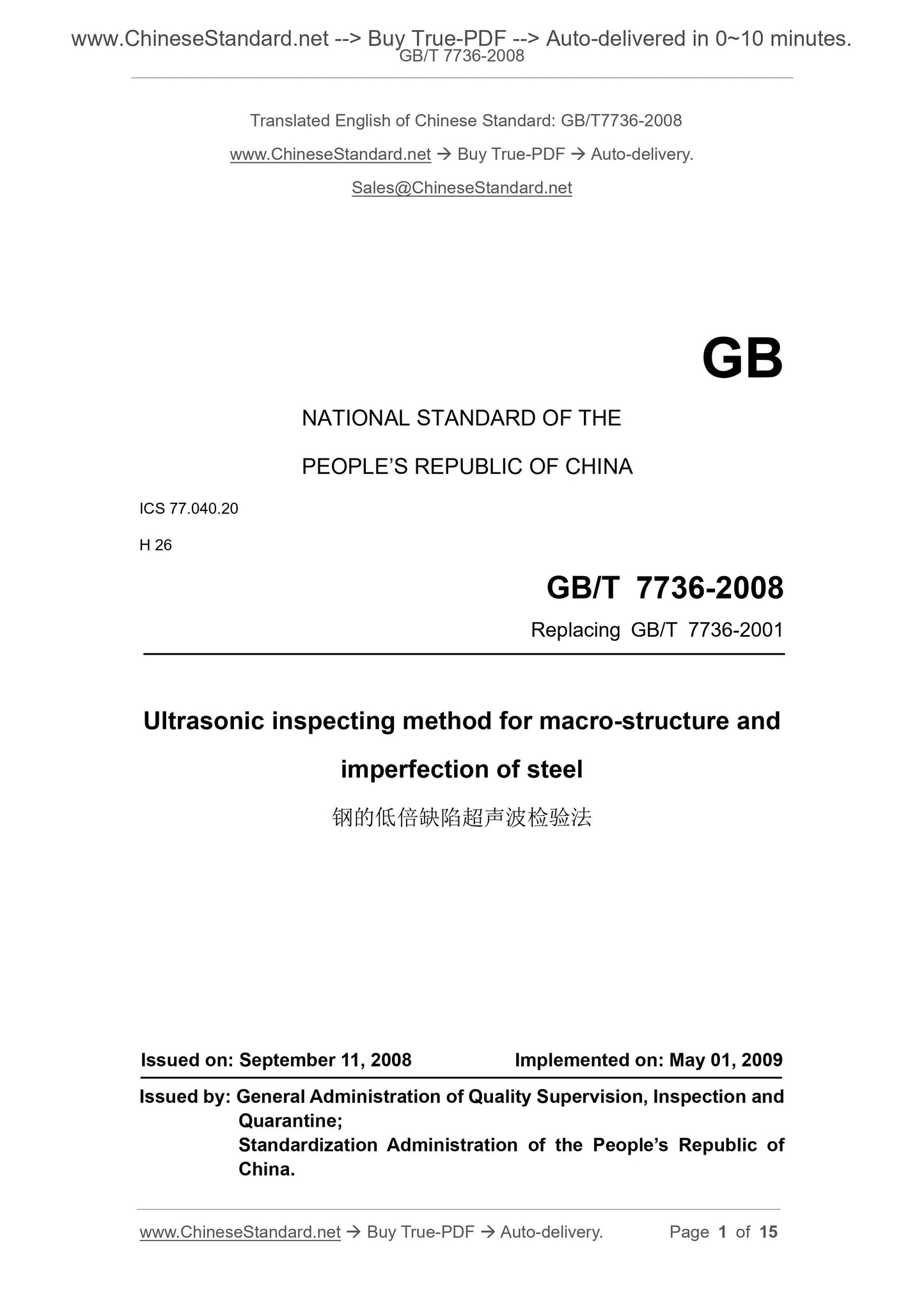
GB/T 7736-2008
NATIONAL STANDARD OF THE
PEOPLE’S REPUBLIC OF CHINA
ICS 77.040.20
H 26
Replacing GB/T 7736-2001
Ultrasonic inspecting method for macro-structure and
imperfection of steel
ISSUED ON: SEPTEMBER 11, 2008
IMPLEMENTED ON: MAY 01, 2009
Issued by: General Administration of Quality Supervision, Inspection and
Quarantine;
Standardization Administration of the People’s Republic of
China.
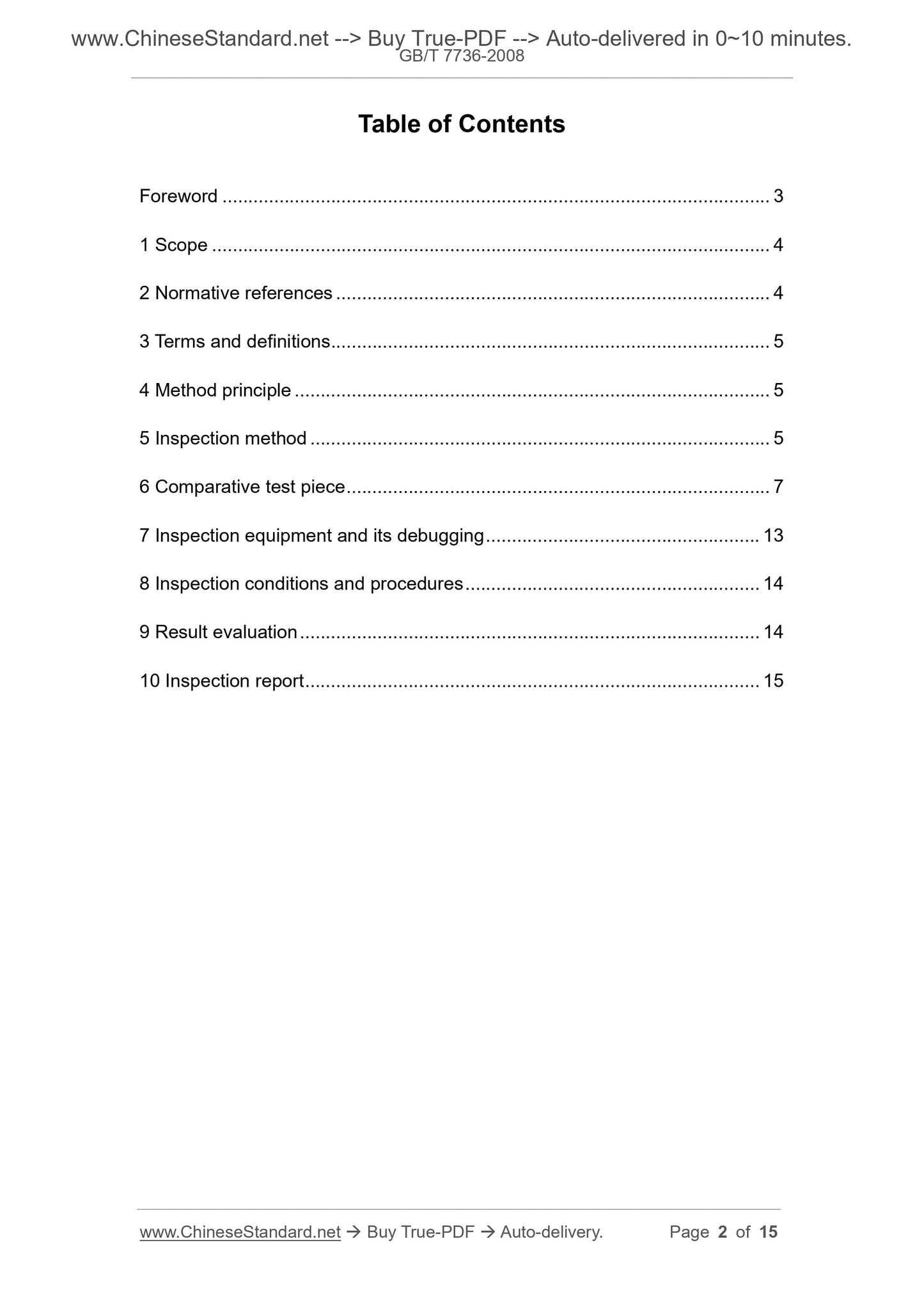
Table of Contents
Foreword ... 3
1 Scope ... 4
2 Normative references ... 4
3 Terms and definitions ... 5
4 Method principle ... 5
5 Inspection method ... 5
6 Comparative test piece ... 7
7 Inspection equipment and its debugging ... 13
8 Inspection conditions and procedures ... 14
9 Result evaluation ... 14
10 Inspection report ... 15
Ultrasonic inspecting method for macro-structure and
imperfection of steel
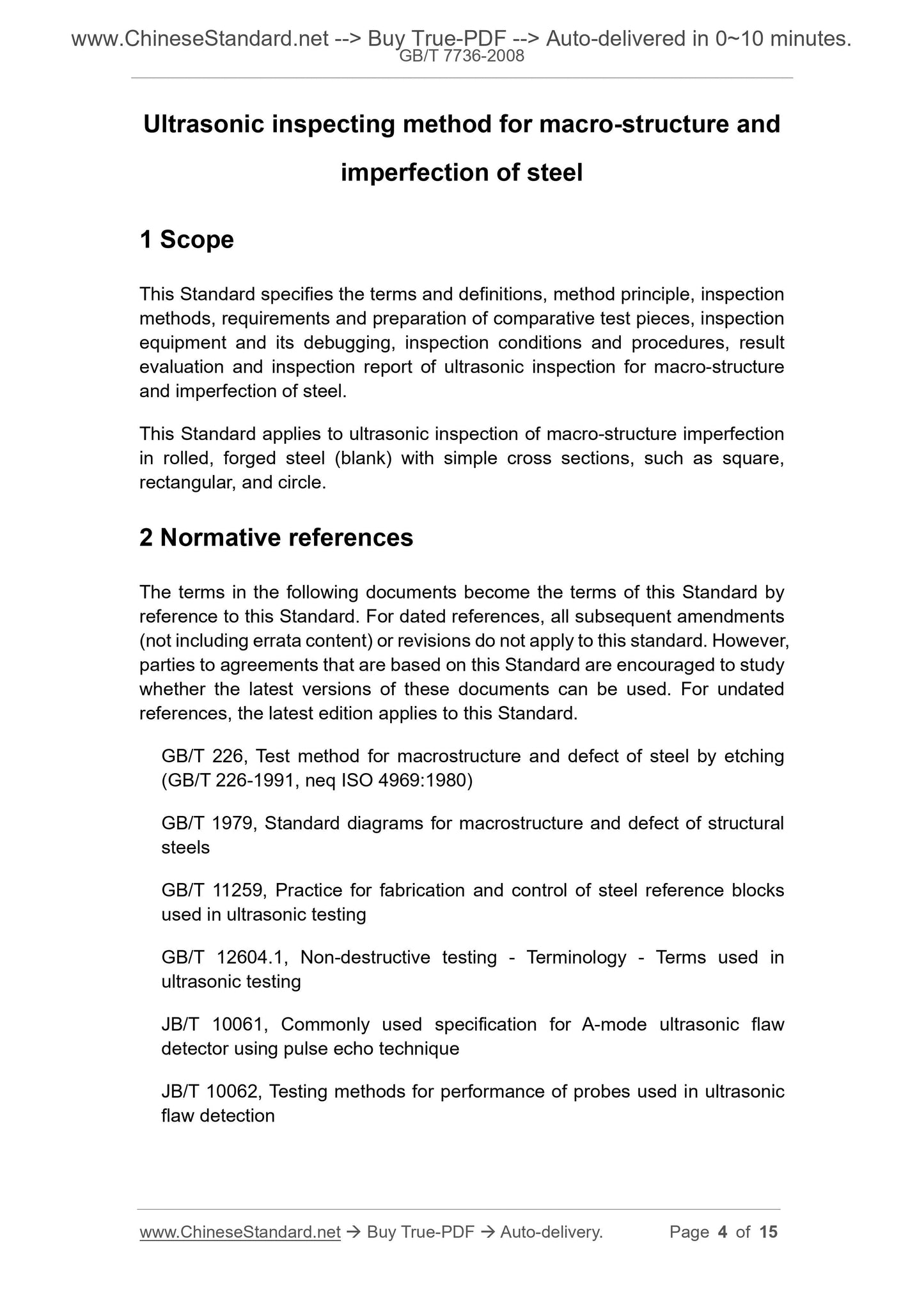
1 Scope
This Standard specifies the terms and definitions, method principle, inspection
methods, requirements and preparation of comparative test pieces, inspection
equipment and its debugging, inspection conditions and procedures, result
evaluation and inspection report of ultrasonic inspection for macro-structure
and imperfection of steel.
This Standard applies to ultrasonic inspection of macro-structure imperfection
in rolled, forged steel (blank) with simple cross sections, such as square,
rectangular, and circle.
2 Normative references
The terms in the following documents become the terms of this Standard by
reference to this Standard. For dated references, all subsequent amendments
(not including errata content) or revisions do not apply to this standard. However,
parties to agreements that are based on this Standard are encouraged to study
whether the latest versions of these documents can be used. For undated
references, the latest edition applies to this Standard.
GB/T 226, Test method for macrostructure and defect of steel by etching
(GB/T 226-1991, neq ISO 4969:1980)
GB/T 1979, Standard diagrams for macrostructure and defect of structural
steels
GB/T 11259, Practice for fabrication and control of steel reference blocks
used in ultrasonic testing
GB/T 12604.1, Non-destructive testing - Terminology - Terms used in
ultrasonic testing
JB/T 10061, Commonly used specification for A-mode ultrasonic flaw
detector using pulse echo technique
JB/T 10062, Testing methods for performance of probes used in ultrasonic
flaw detection
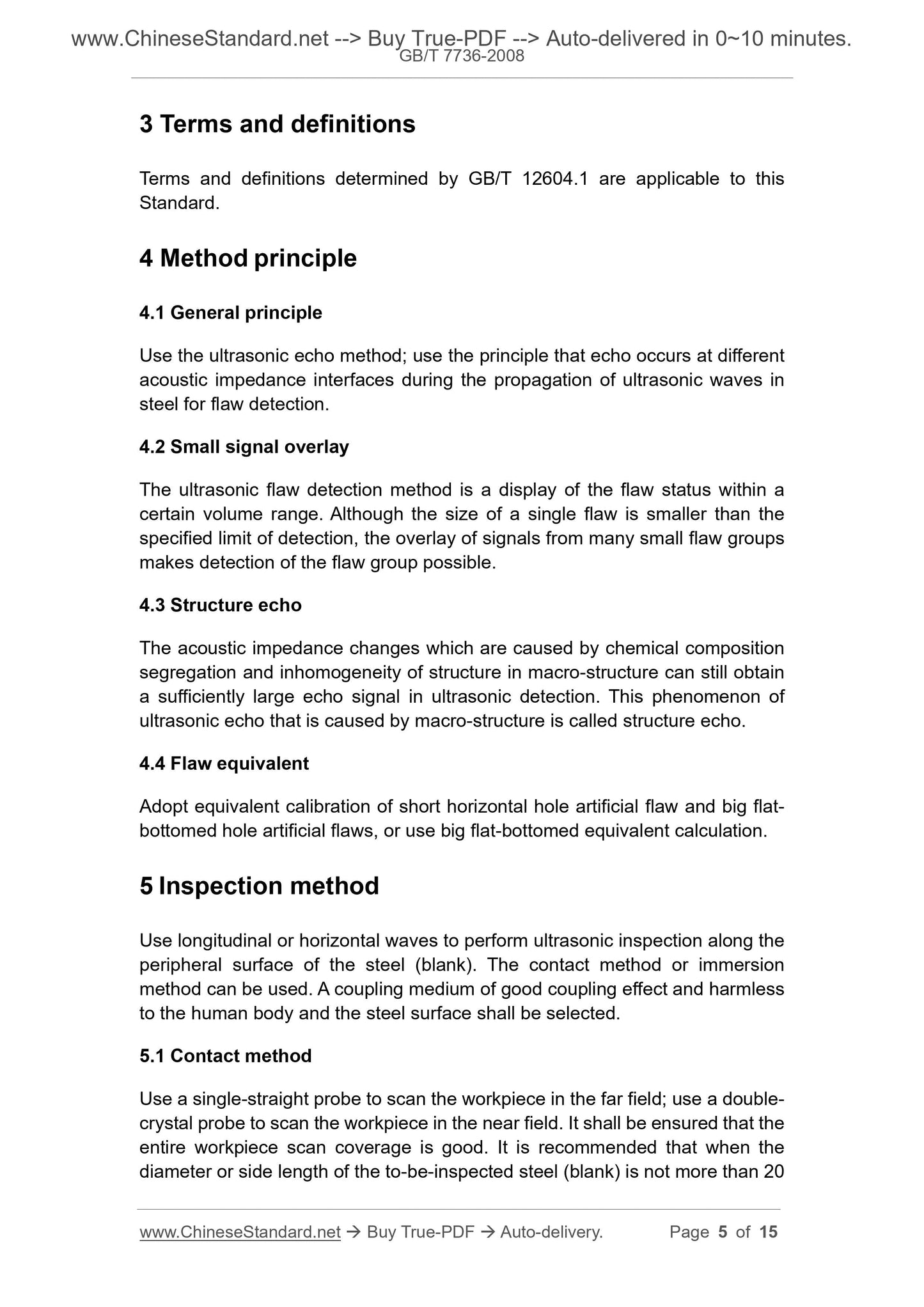
3 Terms and definitions
Terms and definitions determined by GB/T 12604.1 are applicable to this
Standard.
4 Method principle
4.1 General principle
Use the ultrasonic echo method; use the principle that echo occurs at different
acoustic impedance interfaces during the propagation of ultrasonic waves in
steel for flaw detection.
4.2 Small signal overlay
The ultrasonic flaw detection method is a display of the flaw status within a
certain volume range. Although the size of a single flaw is smaller than the
specified limit of detection, the overlay of signals from many small flaw groups
makes detection of the flaw group possible.
4.3 Structure echo
The acoustic impedance changes which are caused by chemical composition
segregation and inhomogeneity of structure in macro-structure can still obtain
a sufficiently large echo signal in ultrasonic detection. This phenomenon of
ultrasonic echo that is caused by macro-structure is called structure echo.
4.4 Flaw equivalent
Adopt equivalent calibration of short horizontal hole artificial flaw and big flat-
bottomed hole artificial flaws, or use big flat-bottomed equivalent calculation.
5 Inspection method
Use longitudinal or horizontal waves to perform ultrasonic inspection along the
peripheral surface of the steel (blank). The contact method or immersion
method can be used. A coupling medium of good coupling effect and harmless
to the human body and the steel surface shall be selected.
5.1 Contact method
Use a single-straight probe to scan the workpiece in the far field; use a double-
crystal probe to scan the workpiece in the near field. It shall be ensured that the
entire workpiece scan coverage is good. It is recommended that when the
diameter or side length of the to-be-inspected steel (blank) is not more than 20
7 Inspection equipment and its debugging
7.1 Inspection equipment
7.1.1 The inspection equipment can be distinguished by the immersion method
and the contact method. It is mainly composed of ultrasonic flaw detectors,
probes, comparative samples, mechanical transmission devices and water
tanks. Its comprehensive sensitivity shall reliably detect the artificial flaws which
are specified in this Standard.
7.1.2 The flaw detector is a device that uses echo technique; the probe is a
straight probe or a double-crystal probe; its electrical performance, combined
performance and test method shall comply with the relevant provisions of JB/T
10061 and JB/T 10062.
7.1.3 In principle, the contact method flaw detection can choose straight probes
or double-crystal probes of different frequencies and specifications according
to the product specifications and requirements.
7.1.4 The immersion method can choose water-immersion probe or focus probe
according to product specifications.
7.2 Equipment debugging
7.2.1 Each time when the flaw detection equipment is re-used or the
specifications are replaced, the specified comparative test piece shall be used
for static and dynamic debugging.
7.2.2 The static debugging mainly adjusts the artificial flaw wave amplitude, the
alarm gate position and amplitude; when setting the alarm sensitivity, it shall be
debugged according to the minimum amplitude of the flaw. If the equivalent
calculation method is used, first adjust the initial sensitivity of the instrument,
that is, adjust the first bottom echo height to 50% to 80% of the full scale of the
phosphor screen in the intact part of the tested sample, as the reference of the
evaluated echo signal. Then, according to the requirements of the tested
sample, calculate the gain value that is needed to be increased according to
Formula (2), to meet the debugging requirements of the specified sensitivity;
then, perform the inspection.
7.2.3 The dynamic debugging mainly adjusts the appropriate scanning speed
to ensure good reproducibility of the manual flaw detection limit.
7.2.4 The scanning speed of the manual operation of the contact method shall
not be greater than 3 m/min.
Share