Skip to product information
1 of 10

PayPal, credit cards. Download editable-PDF and invoice in 1 second!

GB/T 7409.2-2020 English PDF (GBT7409.2-2020)

GB/T 7409.2-2020 English PDF (GBT7409.2-2020)

Regular price $595.00 USD
Regular price Sale price $595.00 USD
Sale Sold out
Shipping calculated at checkout.
Delivery: 3 seconds. Download true-PDF + Invoice.
Get QUOTATION in 1-minute: Click GB/T 7409.2-2020
Historical versions: GB/T 7409.2-2020
Preview True-PDF (Reload/Scroll if blank)

GB/T 7409.2-2020: Excitation systems for synchronous machines--Part 2: Models for power system studies
GB/T 7409.2-2020
GB
NATIONAL STANDARD OF THE
PEOPLE’S REPUBLIC OF CHINA
ICS 29.160.20
K 21
Replacing GB/T 7409.2-2008
Excitation Systems for Synchronous Machines - Part 2:
Models for Power System Studies
ISSUED ON: JUNE 2, 2020
IMPLEMENTED ON: DECEMBER 1, 2020
Issued by: State Administration for Market Regulation;
Standardization Administration of the People’s Republic of China.
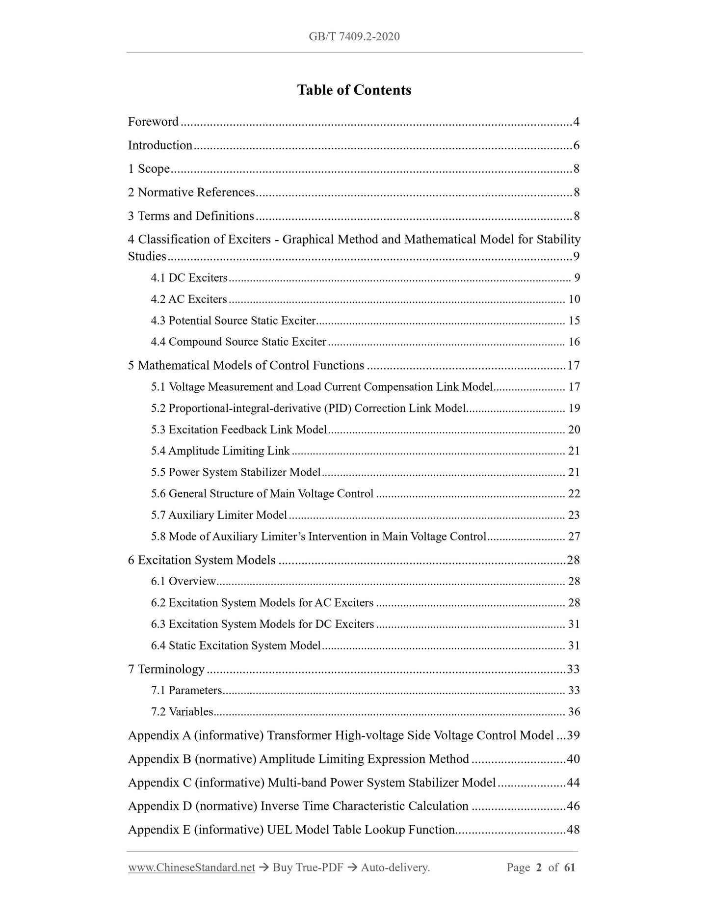
Table of Contents
Foreword ... 4
Introduction ... 6
1 Scope ... 8
2 Normative References ... 8
3 Terms and Definitions ... 8
4 Classification of Exciters - Graphical Method and Mathematical Model for Stability
Studies ... 9
4.1 DC Exciters ... 9
4.2 AC Exciters ... 10
4.3 Potential Source Static Exciter ... 15
4.4 Compound Source Static Exciter ... 16
5 Mathematical Models of Control Functions ... 17
5.1 Voltage Measurement and Load Current Compensation Link Model ... 17
5.2 Proportional-integral-derivative (PID) Correction Link Model ... 19
5.3 Excitation Feedback Link Model ... 20
5.4 Amplitude Limiting Link ... 21
5.5 Power System Stabilizer Model ... 21
5.6 General Structure of Main Voltage Control ... 22
5.7 Auxiliary Limiter Model ... 23
5.8 Mode of Auxiliary Limiter’s Intervention in Main Voltage Control ... 27
6 Excitation System Models ... 28
6.1 Overview ... 28
6.2 Excitation System Models for AC Exciters ... 28
6.3 Excitation System Models for DC Exciters ... 31
6.4 Static Excitation System Model ... 31
7 Terminology ... 33
7.1 Parameters ... 33
7.2 Variables ... 36
Appendix A (informative) Transformer High-voltage Side Voltage Control Model ... 39
Appendix B (normative) Amplitude Limiting Expression Method ... 40
Appendix C (informative) Multi-band Power System Stabilizer Model ... 44
Appendix D (normative) Inverse Time Characteristic Calculation ... 46
Appendix E (informative) UEL Model Table Lookup Function... 48
Appendix F (informative) Integral Reset Representation ... 49
Appendix G (normative) Saturation Function ... 50
Appendix H (normative) Rectifier Regulation Characteristics ... 51
Appendix I (informative) Estimation of Over Excitation Limiter (OEL) Reference
Value ... 53
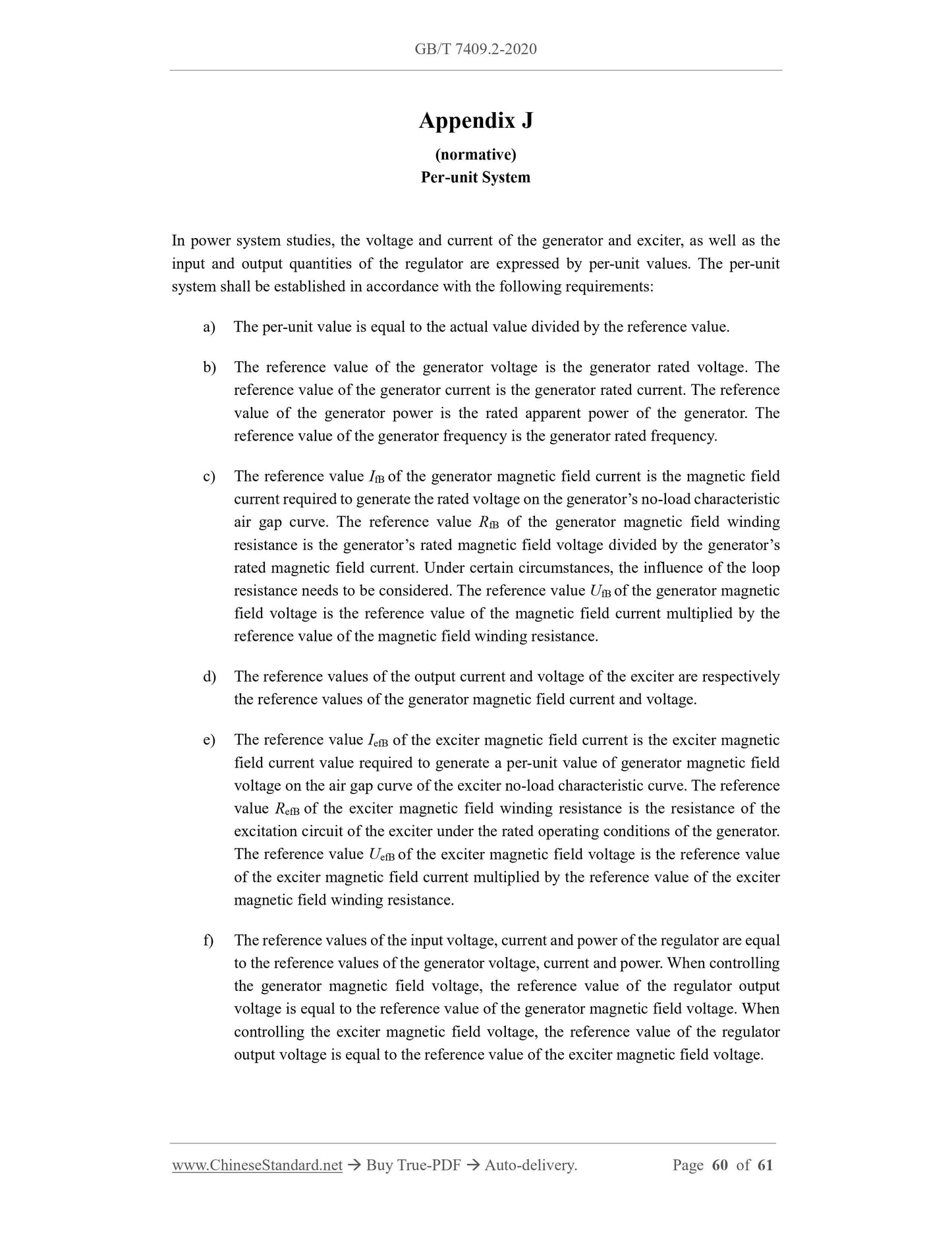
Appendix J (normative) Per-unit System ... 60
Bibliography ... 61
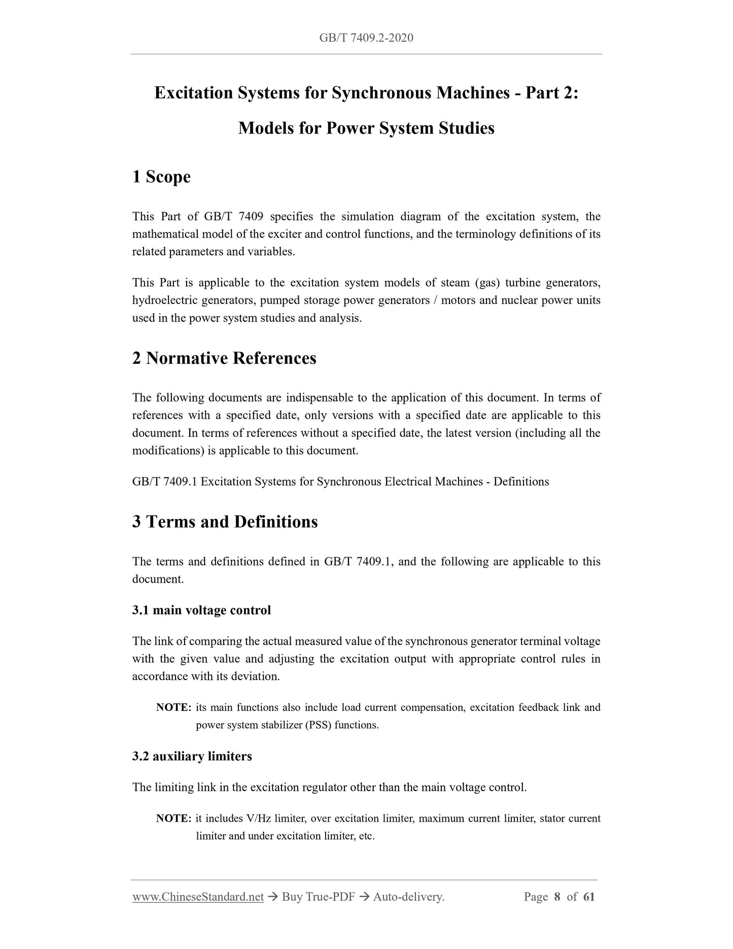
Excitation Systems for Synchronous Machines - Part 2:
Models for Power System Studies
1 Scope
This Part of GB/T 7409 specifies the simulation diagram of the excitation system, the
mathematical model of the exciter and control functions, and the terminology definitions of its
related parameters and variables.
This Part is applicable to the excitation system models of steam (gas) turbine generators,
hydroelectric generators, pumped storage power generators / motors and nuclear power units
used in the power system studies and analysis.
2 Normative References
The following documents are indispensable to the application of this document. In terms of
references with a specified date, only versions with a specified date are applicable to this
document. In terms of references without a specified date, the latest version (including all the
modifications) is applicable to this document.
GB/T 7409.1 Excitation Systems for Synchronous Electrical Machines - Definitions
3 Terms and Definitions
The terms and definitions defined in GB/T 7409.1, and the following are applicable to this
document.
3.1 main voltage control
The link of comparing the actual measured value of the synchronous generator terminal voltage
with the given value and adjusting the excitation output with appropriate control rules in
accordance with its deviation.
NOTE: its main functions also include load current compensation, excitation feedback link and
power system stabilizer (PSS) functions.
3.2 auxiliary limiters
The limiting link in the excitation regulator other than the main voltage control.
NOTE: it includes V/Hz limiter, over excitation limiter, maximum current limiter, stator current
limiter and under excitation limiter, etc.
3.3 maximum current limiter
Under any operating conditions, the output current of the excitation system is instantaneously
limited to not exceed the specified maximum value.
3.4 volts per hertz limiter; VEL
An additional unit or function in a voltage regulator that prevents the voltage-to-frequency ratio
of a synchronous machine or its connected transformer from exceeding an allowable range.
3.5 over excitation limiter; OEL
An additional unit or function in a voltage regulator that limits the output current of the
excitation system to an allowable value.
3.6 stator current limiter; SCL
An additional unit or function in a voltage regulator that limits the stator current within an
allowable value by adjusting the reactive component of the stator current of the synchronous
generator during over excitation or under excitation.
3.7 under excitation limiter; UEL
An additional unit or function in a voltage regulator that limits the reactive power of the
synchronous generator to no less than a specified value under different active loads.
4 Classification of Exciters - Graphical Method and
Mathematical Model for Stability Studies
4.1 DC Exciters
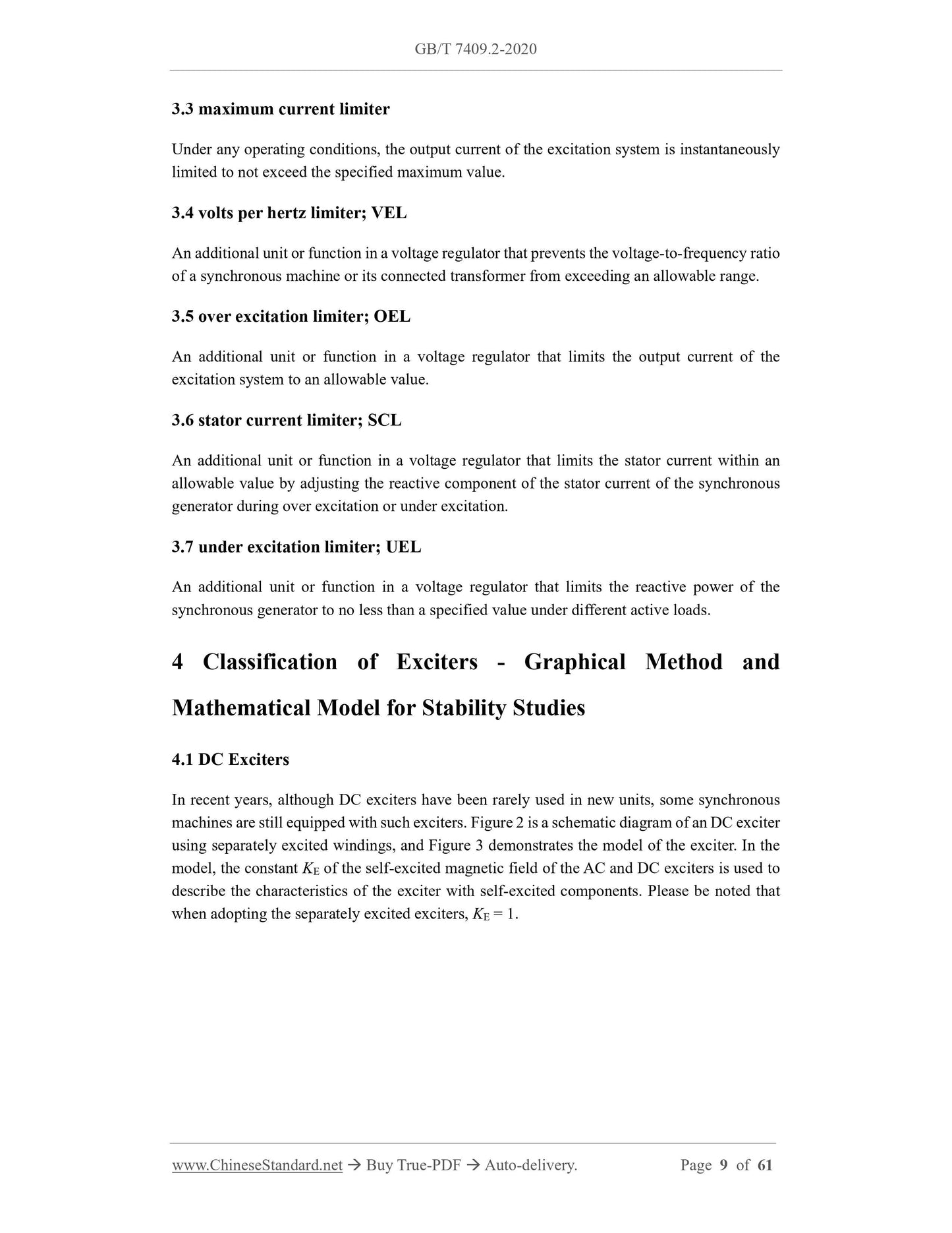
In recent years, although DC exciters have been rarely used in new units, some synchronous
machines are still equipped with such exciters. Figure 2 is a schematic diagram of an DC exciter
using separately excited windings, and Figure 3 demonstrates the model of the exciter. In the
model, the constant KE of the self-excited magnetic field of the AC and DC exciters is used to
describe the characteristics of the exciter with self-excited components. Please be noted that
when adopting the separately excited exciters, KE = 1.
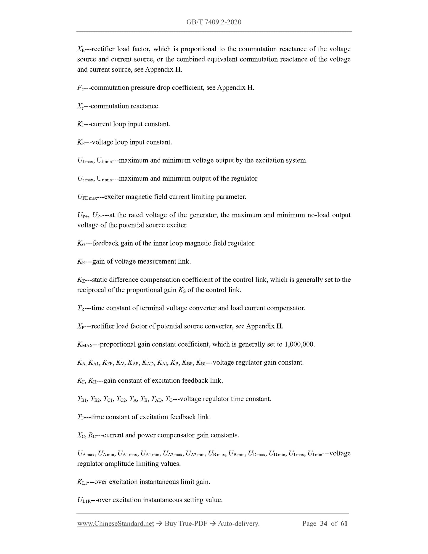
XE---rectifier load factor, which is proportional to the commutation reactance of the voltage
source and current source, or the combined equivalent commutation reactance of the voltage
and current source, see Appendix H.
Fe---commutation pressure drop coefficient, see Appendix H.
X---commutation reactance.
KI---current loop input constant.
KP---voltage loop input constant.
Uf max, Uf min---maximum and minimum voltage output by the excitation system.
Ur max, Ur min---maximum and minimum output of the regulator
UFE max---exciter magnetic field current limiting parameter.
UP+, UP---at the rated voltage of the generator, the maximum and minimum no-load output
voltage of the potential source exciter.
KG---feedback gain of the inner loop magnetic field regulator.
KR---gain of voltage measurement link.
KZ---static difference compensation coefficient of the control link, which is generally set to the
reciprocal of the proportional gain KS of the control link.
TR---time constant of terminal voltage converter and load current compensator.
XP---rectifier load factor of potential source converter, see Appendix H.
KMAX---proportional gain constant coefficient, which is generally set to 1,000,000.
KA, KA1, KFF, KV, KAP, KAD, KAI, KB, KBP, KBI---voltage regulator gain constant.
KF, KH---gain constant of excitation feedback link.
TB1, TB2, TC1, TC2, TA, TB, TAD, TG---voltage regulator time constant.
TF---time constant of excitation feedback link.
XC, RC---current and power compensator gain constants.
UA max, UA min, UA1 max, UA1 min, UA2 max, UA2 min, UB max, UB min, UD max, UD min, UI max, UI min---voltage
regulator amplitude limiting values.
KL1---over excitation instantaneous limit gain.
UL1R---over excitation instantaneous setting value. <...
View full details