1
/
of
12
www.ChineseStandard.us -- Field Test Asia Pte. Ltd.
GB/T 7345-2008 English PDF (GB/T7345-2008)
Regular price
$890.00
Regular price
Sale price
$890.00
Unit price
/
per
Shipping calculated at checkout.
Couldn't load pickup availability
GB/T 7345-2008: General requirements for electrical machine for automatic control system
Delivery: 9 seconds. Download (& Email) true-PDF + Invoice.
Get Quotation: Click GB/T 7345-2008 (Self-service in 1-minute)
Historical versions (Master-website): GB/T 7345-2008
Preview True-PDF (Reload/Scroll-down if blank)
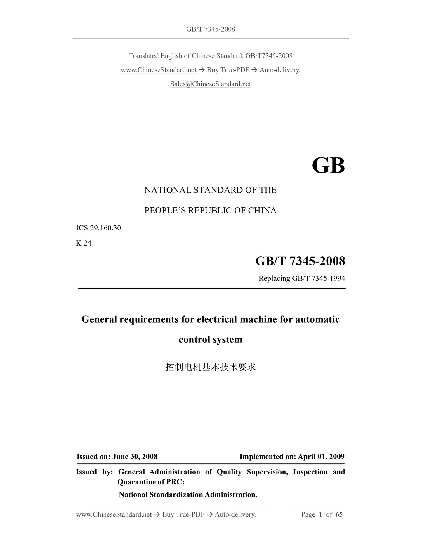
GB/T 7345-2008
GB
NATIONAL STANDARD OF THE
PEOPLE’S REPUBLIC OF CHINA
ICS 29.160.30
K 24
Replacing GB/T 7345-1994
General requirements for electrical machine for automatic
control system
ISSUED ON: JUNE 30, 2008
IMPLEMENTED ON: APRIL 01, 2009
Issued by: General Administration of Quality Supervision, Inspection and
Quarantine of PRC;
National Standardization Administration.
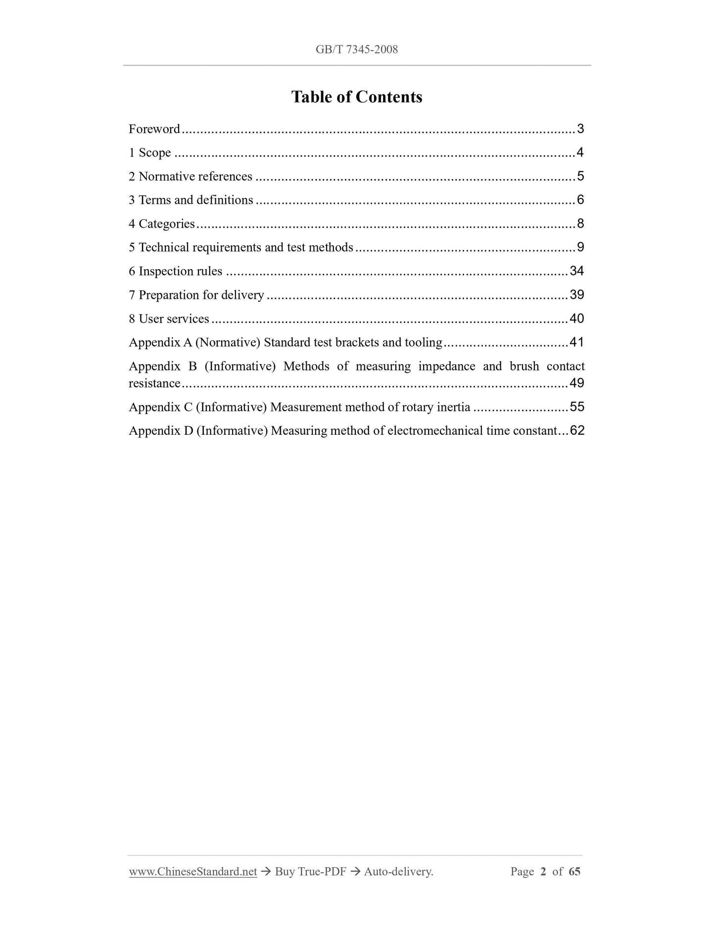
Table of Contents
Foreword ... 3
1 Scope ... 4
2 Normative references ... 5
3 Terms and definitions ... 6
4 Categories ... 8
5 Technical requirements and test methods ... 9
6 Inspection rules ... 34
7 Preparation for delivery ... 39
8 User services ... 40
Appendix A (Normative) Standard test brackets and tooling ... 41
Appendix B (Informative) Methods of measuring impedance and brush contact
resistance ... 49
Appendix C (Informative) Measurement method of rotary inertia ... 55
Appendix D (Informative) Measuring method of electromechanical time constant ... 62
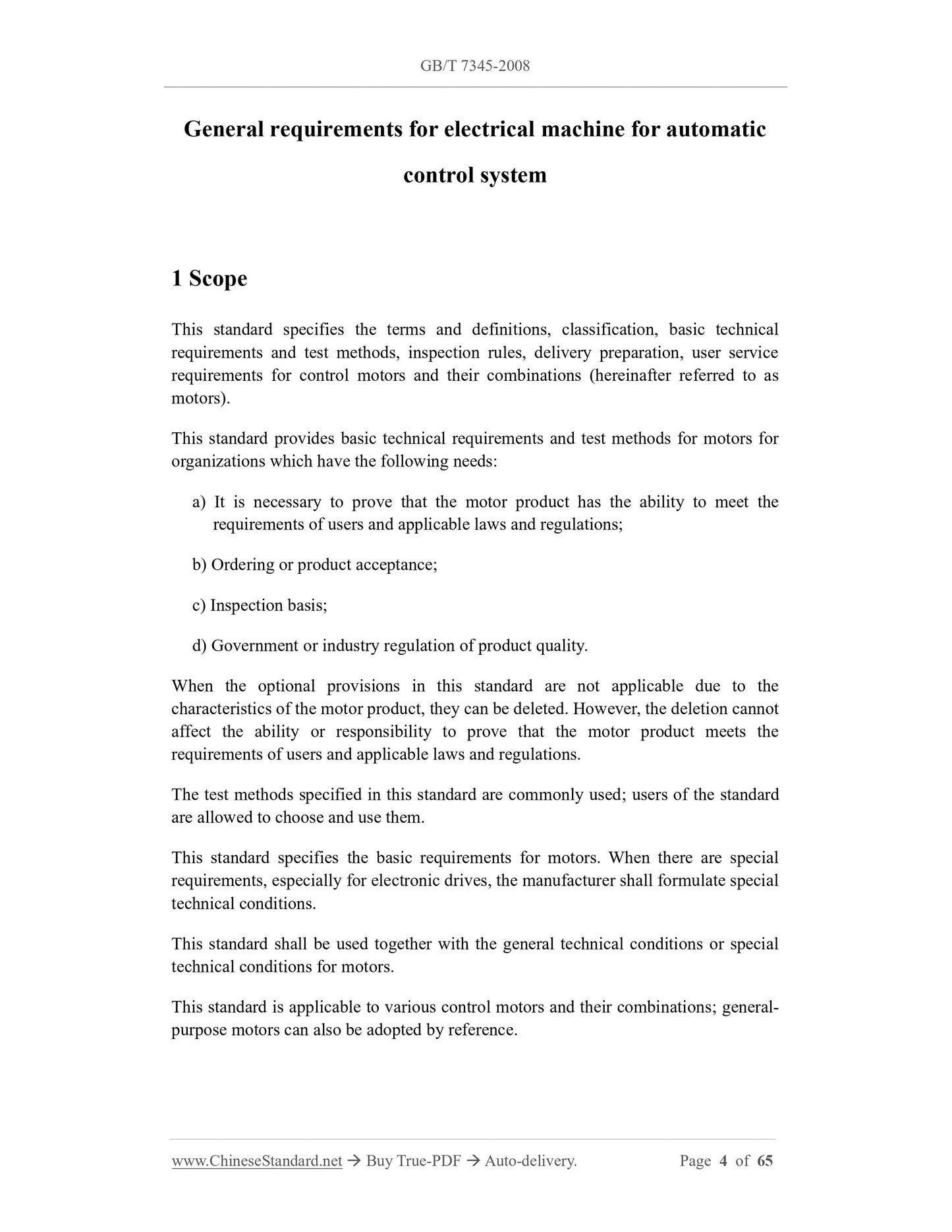
General requirements for electrical machine for automatic
control system
1 Scope
This standard specifies the terms and definitions, classification, basic technical
requirements and test methods, inspection rules, delivery preparation, user service
requirements for control motors and their combinations (hereinafter referred to as
motors).
This standard provides basic technical requirements and test methods for motors for
organizations which have the following needs:
a) It is necessary to prove that the motor product has the ability to meet the
requirements of users and applicable laws and regulations;
b) Ordering or product acceptance;
c) Inspection basis;
d) Government or industry regulation of product quality.
When the optional provisions in this standard are not applicable due to the
characteristics of the motor product, they can be deleted. However, the deletion cannot
affect the ability or responsibility to prove that the motor product meets the
requirements of users and applicable laws and regulations.
The test methods specified in this standard are commonly used; users of the standard
are allowed to choose and use them.
This standard specifies the basic requirements for motors. When there are special
requirements, especially for electronic drives, the manufacturer shall formulate special
technical conditions.
This standard shall be used together with the general technical conditions or special
technical conditions for motors.
This standard is applicable to various control motors and their combinations; general-
purpose motors can also be adopted by reference.
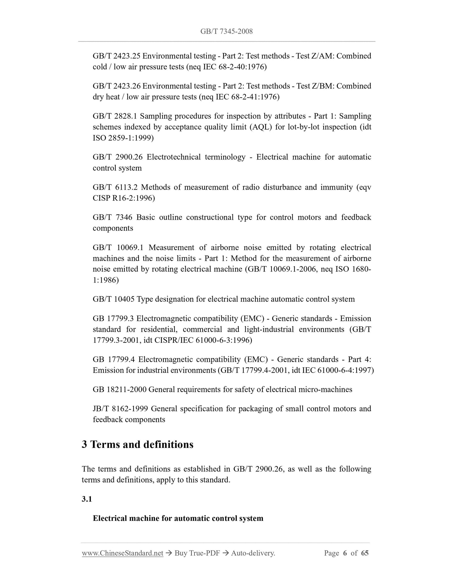
GB/T 2423.25 Environmental testing - Part 2: Test methods - Test Z/AM: Combined
cold / low air pressure tests (neq IEC 68-2-40:1976)
GB/T 2423.26 Environmental testing - Part 2: Test methods - Test Z/BM: Combined
dry heat / low air pressure tests (neq IEC 68-2-41:1976)
GB/T 2828.1 Sampling procedures for inspection by attributes - Part 1: Sampling
schemes indexed by acceptance quality limit (AQL) for lot-by-lot inspection (idt
ISO 2859-1:1999)
GB/T 2900.26 Electrotechnical terminology - Electrical machine for automatic
control system
GB/T 6113.2 Methods of measurement of radio disturbance and immunity (eqv
CISP R16-2:1996)
GB/T 7346 Basic outline constructional type for control motors and feedback
components
GB/T 10069.1 Measurement of airborne noise emitted by rotating electrical
machines and the noise limits - Part 1: Method for the measurement of airborne
noise emitted by rotating electrical machine (GB/T 10069.1-2006, neq ISO 1680-
1:1986)
GB/T 10405 Type designation for electrical machine automatic control system
GB 17799.3 Electromagnetic compatibility (EMC) - Generic standards - Emission
standard for residential, commercial and light-industrial environments (GB/T
17799.3-2001, idt CISPR/IEC 61000-6-3:1996)
GB 17799.4 Electromagnetic compatibility (EMC) - Generic standards - Part 4:
Emission for industrial environments (GB/T 17799.4-2001, idt IEC 61000-6-4:1997)
GB 18211-2000 General requirements for safety of electrical micro-machines
JB/T 8162-1999 General specification for packaging of small control motors and
feedback components
3 Terms and definitions
The terms and definitions as established in GB/T 2900.26, as well as the following
terms and definitions, apply to this standard.
3.1
Electrical machine for automatic control system
5.3.2 Test methods
5.3.2.1 Lead wire
Put the lead-out end of the motor's lead wire downward. Apply the force specified in
5.3.1.2 vertically downward on the terminal. When applying force, the conductor core
and insulation layer shall be evenly stressed. The force shall be applied in all directions
for 5 s ~ 10 s.
For the cable outlet from the rear end of the motor along the motor axis, first make the
motor shaft extend vertically upward; rotate the motor 90° to bring the shaft into a
horizontal position; rotate the casing 360° clockwise and counterclockwise around the
axis.
For the outlet along the radial direction of the motor, first place the motor horizontally
with the lead wire downward; rotate the motor vertically 90° to make the shaft extend
vertically upward; rotate the casing around the axis of the outlet hole 360° clockwise
and counterclockwise.
After the test, it shall meet the requirements of 5.3.1.2.
5.3.2.2 Threaded terminals
Fix the motor. Apply the pressure and tension specified in 5.3.1.3 along the axial
direction of the threaded terminal. Then apply torque to the end of the threaded terminal
circumferentially. The torque is gradually and evenly applied (without any impact); it
is maintained for 5 s ~ 10 s after reaching the torque value specified in 5.3.1.3. After
the test, it shall meet the requirements of 5.3.1.3.
5.3.2.3 Wiring lugs (terminal)
Fix the motor. Apply a tensile force to its end along the axial direction of the lug
(terminal). The tensile force shall be gradually and evenly applied (without any impact);
it shall be maintained for 5 s ~ 10 s after reaching the tensile force value specified in
5.3.1.4. After the test, it shall meet the requirements of 5.3.1.4.
5.4 Appearance and installation dimensions
5.4.1 Technical requirements
The manufacturer shall stipulate the appearance and installation dimensions of the
motor. The appearance and installation dimensions shall comply with the general
technical conditions or special technical conditions of the motor. Unless otherwise
specified, the manufacturer shall deliver the appearance and installation dimensions
drawings when delivering the motor.
Note: Appearance and installation dimensions include dimensional tolerances.
5.4.2 Test methods
Select the type of measuring tool and accuracy level, according to the shape and
installation dimensions of the motor. Place the motor under normal temperature
conditions and make measurements one by one, after it reaches a stable non-operating
temperature. The results shall meet the requirements of 5.4.1.
Note: Instant measurement at room temperature is allowed, as long as the measurement
accuracy is not affected.
5.5 Radial clearance
5.5.1 Technical requirements
The radial clearance of the motor shaft is related to the machining accuracy of the motor
bearing chamber, the bearing radial clearance, the radial stress of the shaft extension.
When required, the manufacturer shall specify the radial clearance size and radial force
of the motor shaft. The radial clearance shall comply with the general technical
conditions or special technical conditions of the motor.
5.5.2 Test methods
Install the motor firmly and horizontally axially. Place the measuring head of a dial
indicator on the shaft extension surface, as close to the bearing position as possible;
apply the force specified in the general technical conditions or special technical
conditions, on the shaft in the direction perpendicular to the axial direction. First in one
direction and then in the opposite direction, observe the difference between the two
readings of the dial indicator, which is the measured value of radial clearance; its size
shall meet the requirements of 5.5.1.
Note: The position of applying force shall be close to the position of the measuring head of the
dial indicator. The line connecting the measuring point on the meter head and the force
application point shall be parallel to the motor axis.
5.6 Axial clearance
5.6.1 Technical requirements
The axial clearance of the motor is related to the axial dimensional matching accuracy
of the motor, the elasticity of the axial washer, and the axial force. When required, the
manufacturer shall specify the axial clearance and axial force of the motor shaft. The
axial clearance shall comply with the general technical conditions or special technical
conditions of the motor.
5.6.2 Test methods
Install the motor firmly and horizontally axially. It can place the measuring head of a
This requirement only applies to motors with stop mounting. The verticality of the
installation mating end face is related to the machining accuracy of the motor
installation stop mating end face and the assembly quality of the stator and rotor. When
required, the manufacturer shall specify the verticality of the installation end face. The
verticality of the installation mating end face shall comply with the general technical
conditions or special technical conditions of the motor.
5.9.2 Test methods
To fix the motor rotor, it can place the measuring head of a dial indicator on the stator
installation mating end face. Rotate the motor stator. Measure the runout of three circles
evenly on the end face. Take the maximum value, which is the verticality of the
installation mating end face. Its size shall comply with the requirements of 5.9.1.
5.10 Friction torque
5.10.1 Technical requirements
5.10.1.1 Overview
Friction torque is one of the parameters that measures the rotational flexibility of the
motor. It includes static friction torque and excitation static friction torque.
5.10.1.2 Static friction torque
Static friction torque is the frictional resistance torque, that needs to be overcome when
the rotor starts to rotate at any position, when the motor is not energized and the
armature winding is open circuit. When required, the manufacturer shall specify the
static friction torque. The static friction torque shall comply with the general technical
conditions or special technical conditions of the motor.
5.10.1.3 Excitation static friction torque
The excitation static friction torque is the resistance torque, that needs to be overcome
to make the rotor start to rotate, at any position under specified excitation conditions.
When required, the manufacturer shall specify the excitation static friction torque. The
excitation static friction torque shall comply with the general technical conditions or
special technical conditions of the motor.
5.10.2 Test methods
5.10.2.1 Static friction torque
According to the frame size of the motor, select the corresponding disc size, as shown
in Figure A.5 in Appendix A. According to the specified static friction torque value,
select the friction torque test weight with the corresponding specifications shown in
Figure A.6 in Appendix A.
Rigidly fix the disc on the motor shaft extension. The selected test weight is firmly
suspended at a fixed position on the disc.
The motor casing rotates in two opposite directions, at a constant speed of 4 r/min ~ 6
r/min, with at least three revolutions in each direction. During the rotation process in
each direction, if the disc does not rotate more than one revolution, the static friction
torque meets the requirements of 5.10.1.2.
Other equivalent methods of measurement are allowed.
5.10.2.2 Excitation static friction torque
Excite the motor according to the specified excitation conditions. Check the excitation
static friction torque, according to the method of 5.10.2.1. The excitation static friction
torque shall meet the requirements of 5.10.1.3.
Other equivalent methods of measurement are allowed.
5.11 No-load starting voltage
5.11.1 Technical requirements
No-load starting voltage is one of the indicators to measure the sensitivity of the motor.
When required, the manufacturer shall specify the no-load starting voltage value. The
no-load starting voltage shall comply with the general technical conditions or special
technical conditions of the motor.
5.11.2 Test methods
Before the test, fix the motor stator and let the motor run without load for 3 ~ 5 minutes.
During the test, at any starting position of the motor rotor, the control voltage (or
armature voltage) is gradually increased from zero evenly and slowly, until the rotor
begins to rotate continuously. Read the control voltage (or armature voltage) value at
this time. For motors with electrical excitation requirements, apply rated excitation
voltage to the excitation winding. Each rotation direction is randomly performed three
times, a total of six times in both directions. Take the maximum value of the six control
voltages (or armature voltage), which is the no-load starting voltage. Its value shall
comply with the requirements of 5.11.1.
5.12 Control characteristics
5.12.1 Technical requirements
Control characteristics are the unique ability to control a motor. It includes rated
parameters, control range, accuracy, response capabilities, etc. The manufacturer shall
stipulate the technical indicators of its control characteristics, according to the purpose
of the motor. The technical indicators shall meet the requirements of users and
5.15.1 Technical requirements
Impedance is a unique technical parameter of an AC motor. It reflects the matching
ability of the motor and its connected electrical equipment. When required, the
manufacturer shall specify the motor impedance.
5.15.2 Test methods
Install the motor on the standard test bracket. Run it to a stable operating temperature,
according to the specified test frequency and voltage. Then use t...
Share