GB/T 7251.6-2015 English PDF (GBT7251.6-2015)
Regular price
$145.00 USD
Regular price
Sale price
$145.00 USD
Unit price
/
per
Delivery: 3 seconds. Download true-PDF + Invoice.
Get QUOTATION in 1-minute: Click GB/T 7251.6-2015
Historical versions: GB/T 7251.6-2015
Preview True-PDF (Reload/Scroll if blank)
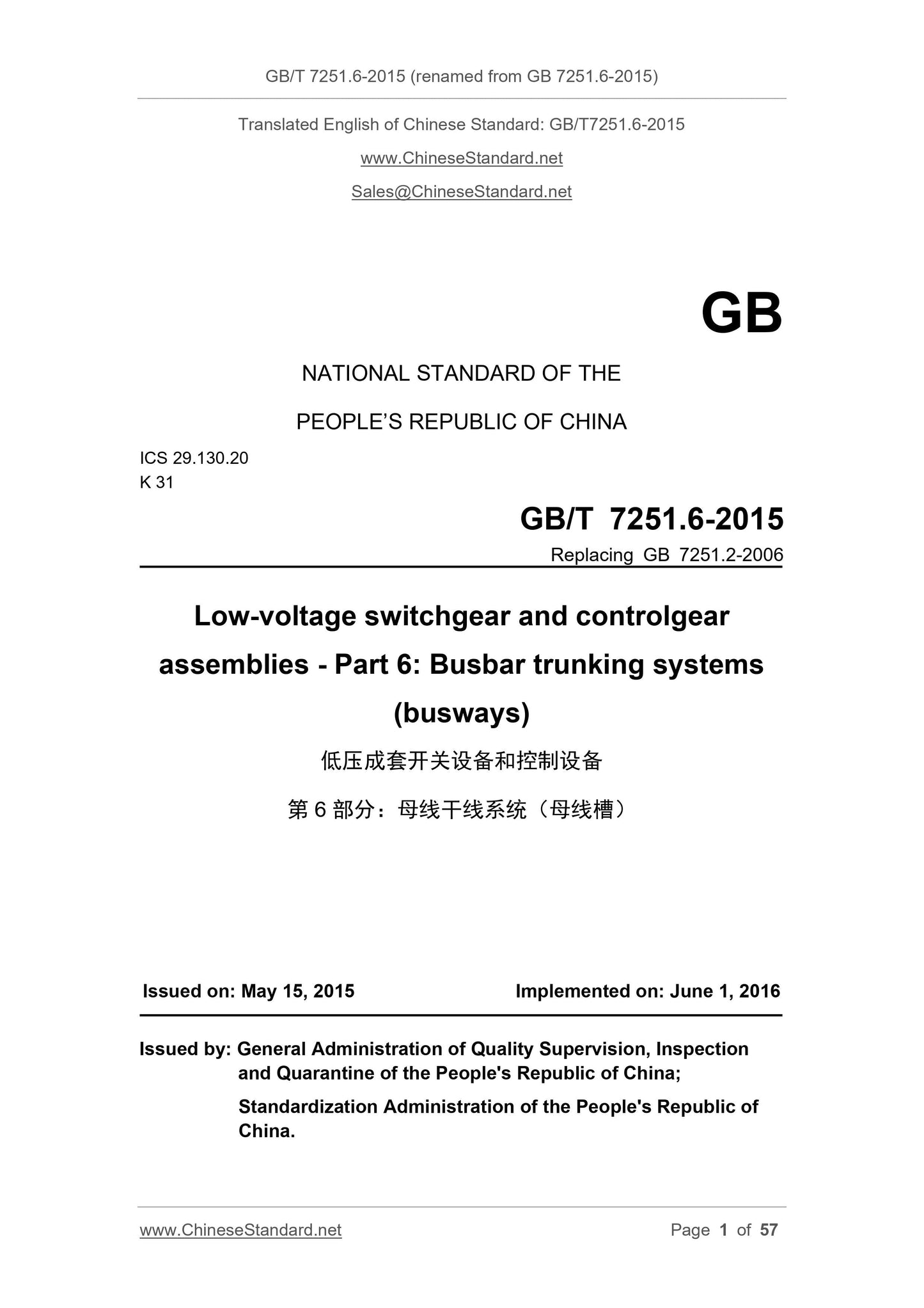
GB/T 7251.6-2015: Low-voltage switchgear and controlgear assemblies -- Part 6: Busbar trunking systems (busways)
GB/T 7251.6-2015 (renamed from GB 7251.6-2015)
GB
NATIONAL STANDARD OF THE
PEOPLE’S REPUBLIC OF CHINA
ICS 29.130.20
K 31
GB/T 7251.6-2015
Replacing GB 7251.2-2006
Low-voltage switchgear and controlgear
assemblies - Part 6: Busbar trunking systems
(busways)
ISSUED ON: MAY 15, 2015
IMPLEMENTED ON: JUNE 1, 2016
Issued by: General Administration of Quality Supervision, Inspection
and Quarantine of the People's Republic of China;
Standardization Administration of the People's Republic of
China.
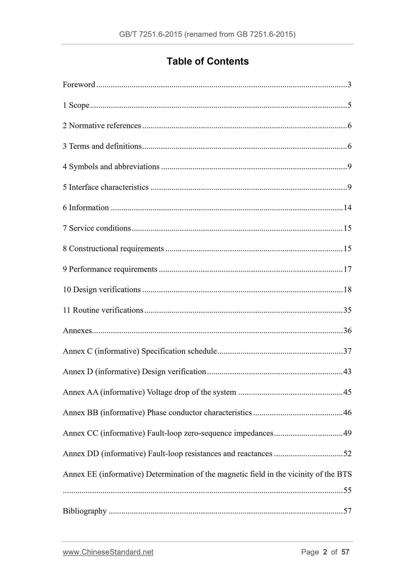
Table of Contents
Foreword ... 3
1 Scope ... 5
2 Normative references ... 6
3 Terms and definitions ... 6
4 Symbols and abbreviations ... 9
5 Interface characteristics ... 9
6 Information ... 14
7 Service conditions ... 15
8 Constructional requirements ... 15
9 Performance requirements ... 17
10 Design verifications ... 18
11 Routine verifications ... 35
Annexes... 36
Annex C (informative) Specification schedule ... 37
Annex D (informative) Design verification ... 43
Annex AA (informative) Voltage drop of the system ... 45
Annex BB (informative) Phase conductor characteristics ... 46
Annex CC (informative) Fault-loop zero-sequence impedances ... 49
Annex DD (informative) Fault-loop resistances and reactances ... 52
Annex EE (informative) Determination of the magnetic field in the vicinity of the BTS
... 55
Bibliography ... 57
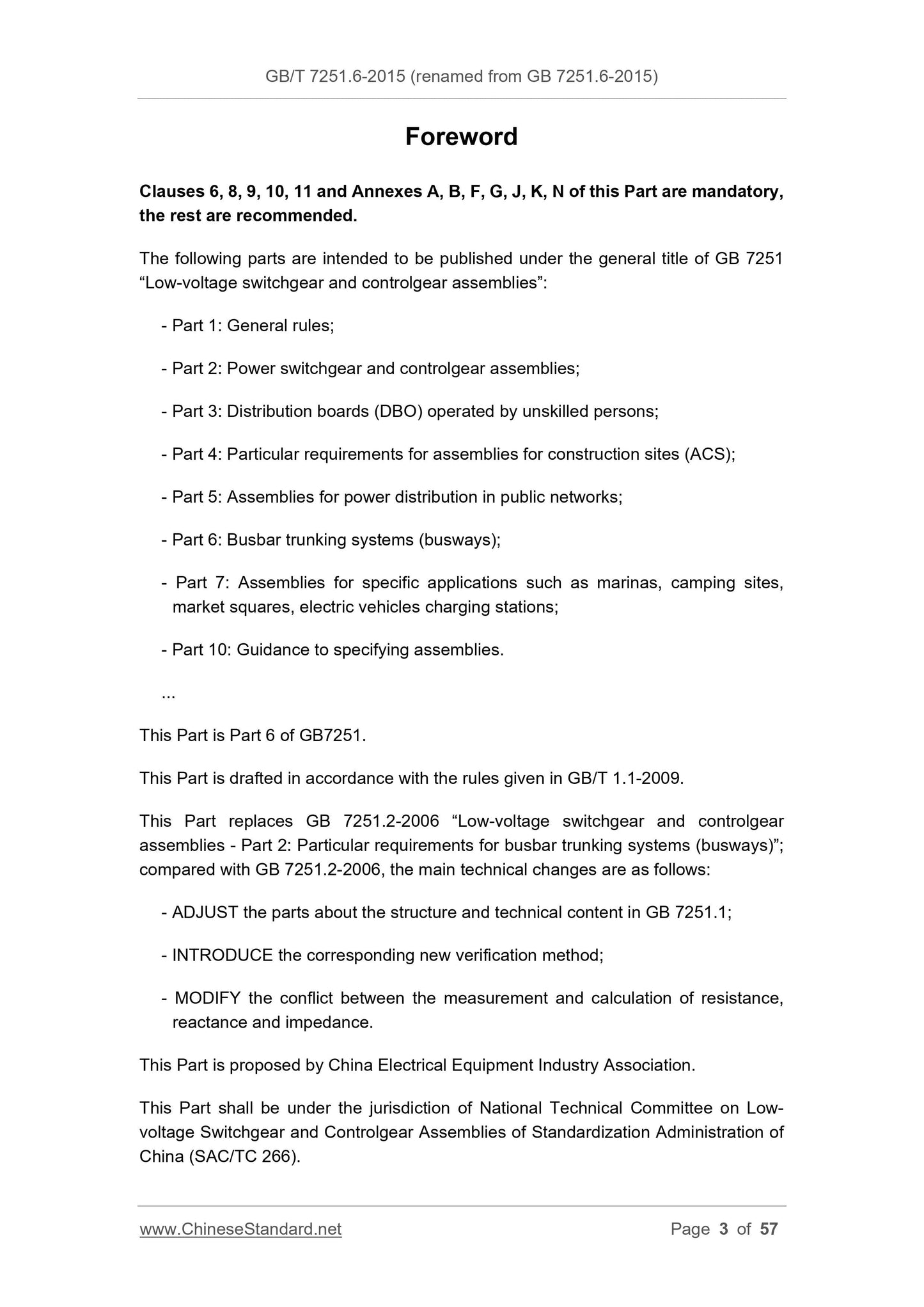
Foreword
Clauses 6, 8, 9, 10, 11 and Annexes A, B, F, G, J, K, N of this Part are mandatory,
the rest are recommended.
The following parts are intended to be published under the general title of GB 7251
“Low-voltage switchgear and controlgear assemblies”:
- Part 1: General rules;
- Part 2: Power switchgear and controlgear assemblies;
- Part 3: Distribution boards (DBO) operated by unskilled persons;
- Part 4: Particular requirements for assemblies for construction sites (ACS);
- Part 5: Assemblies for power distribution in public networks;
- Part 6: Busbar trunking systems (busways);
- Part 7: Assemblies for specific applications such as marinas, camping sites,
market squares, electric vehicles charging stations;
- Part 10: Guidance to specifying assemblies.
...
This Part is Part 6 of GB7251.
This Part is drafted in accordance with the rules given in GB/T 1.1-2009.
This Part replaces GB 7251.2-2006 “Low-voltage switchgear and controlgear
assemblies - Part 2: Particular requirements for busbar trunking systems (busways)”;
compared with GB 7251.2-2006, the main technical changes are as follows:
- ADJUST the parts about the structure and technical content in GB 7251.1;
- INTRODUCE the corresponding new verification method;
- MODIFY the conflict between the measurement and calculation of resistance,
reactance and impedance.
This Part is proposed by China Electrical Equipment Industry Association.
This Part shall be under the jurisdiction of National Technical Committee on Low-
voltage Switchgear and Controlgear Assemblies of Standardization Administration of
China (SAC/TC 266).
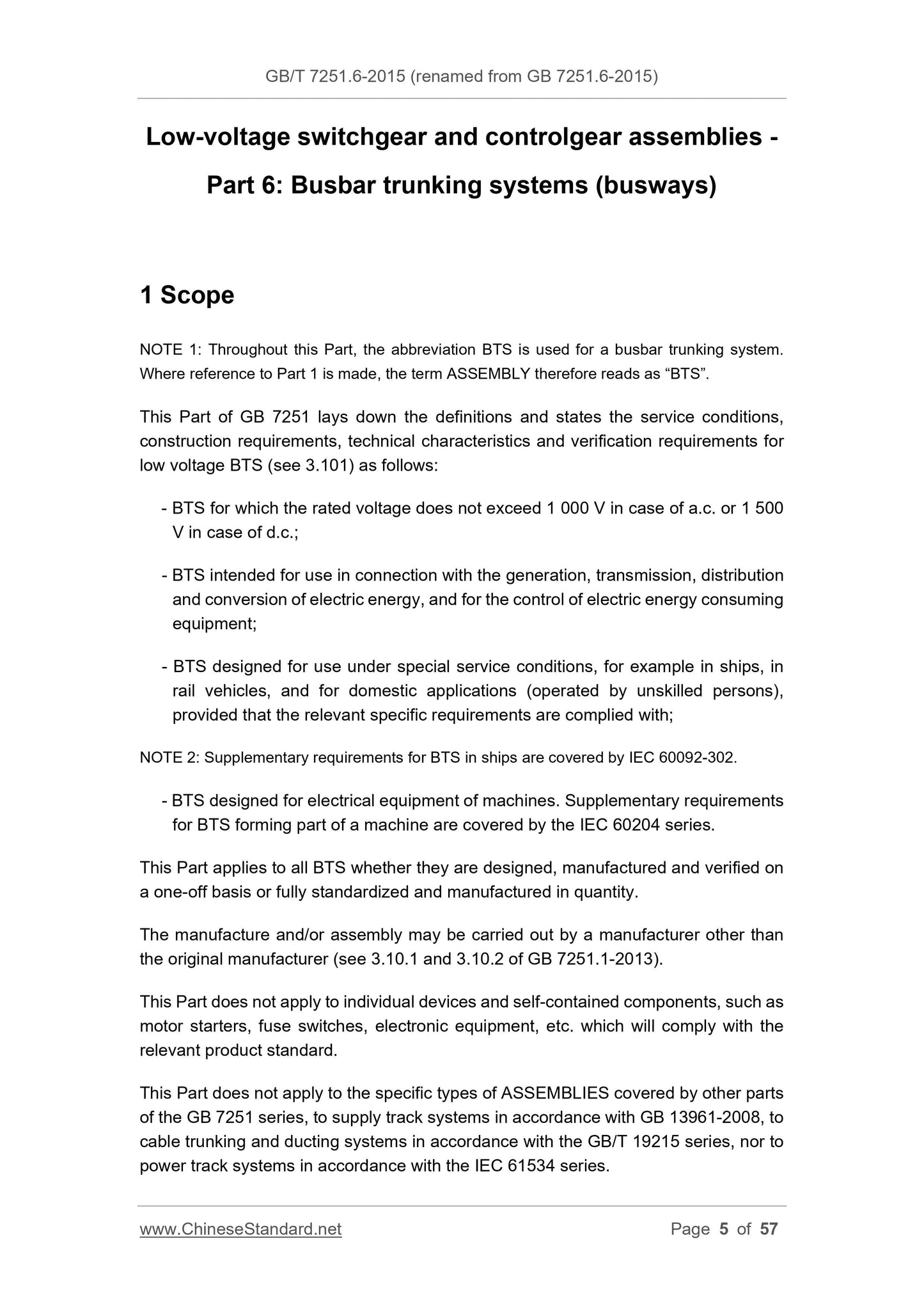
Low-voltage switchgear and controlgear assemblies -
Part 6: Busbar trunking systems (busways)
1 Scope
NOTE 1: Throughout this Part, the abbreviation BTS is used for a busbar trunking system.
Where reference to Part 1 is made, the term ASSEMBLY therefore reads as “BTS”.
This Part of GB 7251 lays down the definitions and states the service conditions,
construction requirements, technical characteristics and verification requirements for
low voltage BTS (see 3.101) as follows:
- BTS for which the rated voltage does not exceed 1 000 V in case of a.c. or 1 500
V in case of d.c.;
- BTS intended for use in connection with the generation, transmission, distribution
and conversion of electric energy, and for the control of electric energy consuming
equipment;
- BTS designed for use under special service conditions, for example in ships, in
rail vehicles, and for domestic applications (operated by unskilled persons),
provided that the relevant specific requirements are complied with;
NOTE 2: Supplementary requirements for BTS in ships are covered by IEC 60092-302.
- BTS designed for electrical equipment of machines. Supplementary requirements
for BTS forming part of a machine are covered by the IEC 60204 series.
This Part applies to all BTS whether they are designed, manufactured and verified on
a one-off basis or fully standardized and manufactured in quantity.
The manufacture and/or assembly may be carried out by a manufacturer other than
the original manufacturer (see 3.10.1 and 3.10.2 of GB 7251.1-2013).
This Part does not apply to individual devices and self-contained components, such as
motor starters, fuse switches, electronic equipment, etc. which will comply with the
relevant product standard.
This Part does not apply to the specific types of ASSEMBLIES covered by other parts
of the GB 7251 series, to supply track systems in accordance with GB 13961-2008, to
cable trunking and ducting systems in accordance with the GB/T 19215 series, nor to
power track systems in accordance with the IEC 61534 series.
10.2.101.3 Resistance of the enclosure to crushing
A straight BTU shall be subjected to a crushing force, successively at four or more
points, including one point between adjacent insulators, if any.
The BTU shall be supported horizontally on a flat surface and the force shall be applied
through a rigid plate equal to the width of the BTU and 120 mm long.
The crushing force shall at least be equal to 4 times the weight of 1 m length, for BTS
stated for normal mechanical loads; a mass of 90 kg shall be added for BTS stated for
heavy mechanical loads.
The duration of the test shall be at least 5 min per point.
10.2.101.4 Results to be obtained
During and after the tests according to 10.2.101.1 to 10.2.101.3, there shall be neither
break, nor permanent deformation of the enclosure which would compromise the
degree of protection, reduce the clearances and creepage distances to values lower
than those specified in 8.3, or impair the correct insertion of incoming and outgoing
units.
The protective circuit shall remain functional and the test samples shall withstand the
dielectric test according to 10.9.2 of GB 7251.1-2013.
10.2.102 Thermal cycling test
10.2.102.1 General
Plug-in tap-off units shall be submitted to a thermal cycling test.
10.2.102.2 Test sample
If the same design of the plug assembly is used for a range of tap-off units of different
rated currents or of different protective devices, a test on one combination of a BTU
and a tap-off unit is considered to be representative of the range. The design of the
plug assembly includes the physical characteristics and the material and surface finish
(e.g. plating), if applicable.
A tap-off unit incorporating fuses shall be fitted with the maximum size of fuses
specified by the original manufacturer. A tap-off unit incorporating a circuit-breaker
shall be fitted with a circuit-breaker of the maximum rating specified by the original
manufacturer.
The tap-off unit shall be arranged and loaded as in 10.10.2.3.6.