Skip to product information
1 of 7

PayPal, credit cards. Download editable-PDF & invoice in 1 second!

GB/T 7233.1-2023 English PDF (GBT7233.1-2023)

GB/T 7233.1-2023 English PDF (GBT7233.1-2023)

Regular price $500.00 USD
Regular price Sale price $500.00 USD
Sale Sold out
Shipping calculated at checkout.
Delivery: 3 seconds. Download true-PDF + Invoice.
Get Quotation: Click GB/T 7233.1-2023 (Self-service in 1-minute)
Historical versions (Master-website): GB/T 7233.1-2023
Preview True-PDF (Reload/Scroll-down if blank)

GB/T 7233.1-2023: Steel castings -- Ultrasonic testing -- Part 1: Steel castings for general purposes
GB/T 7233.1-2023 English name.Steel castings -- Ultrasonic testing -- Part 1.Steel castings for general purposes
National Standards of People's Republic of China
Replace GB/T 7233.1-2009
Ultrasonic testing of steel castings
Part 1.Steel castings for general purposes
State Administration for Market Regulation
Released by the National Standardization Management Committee
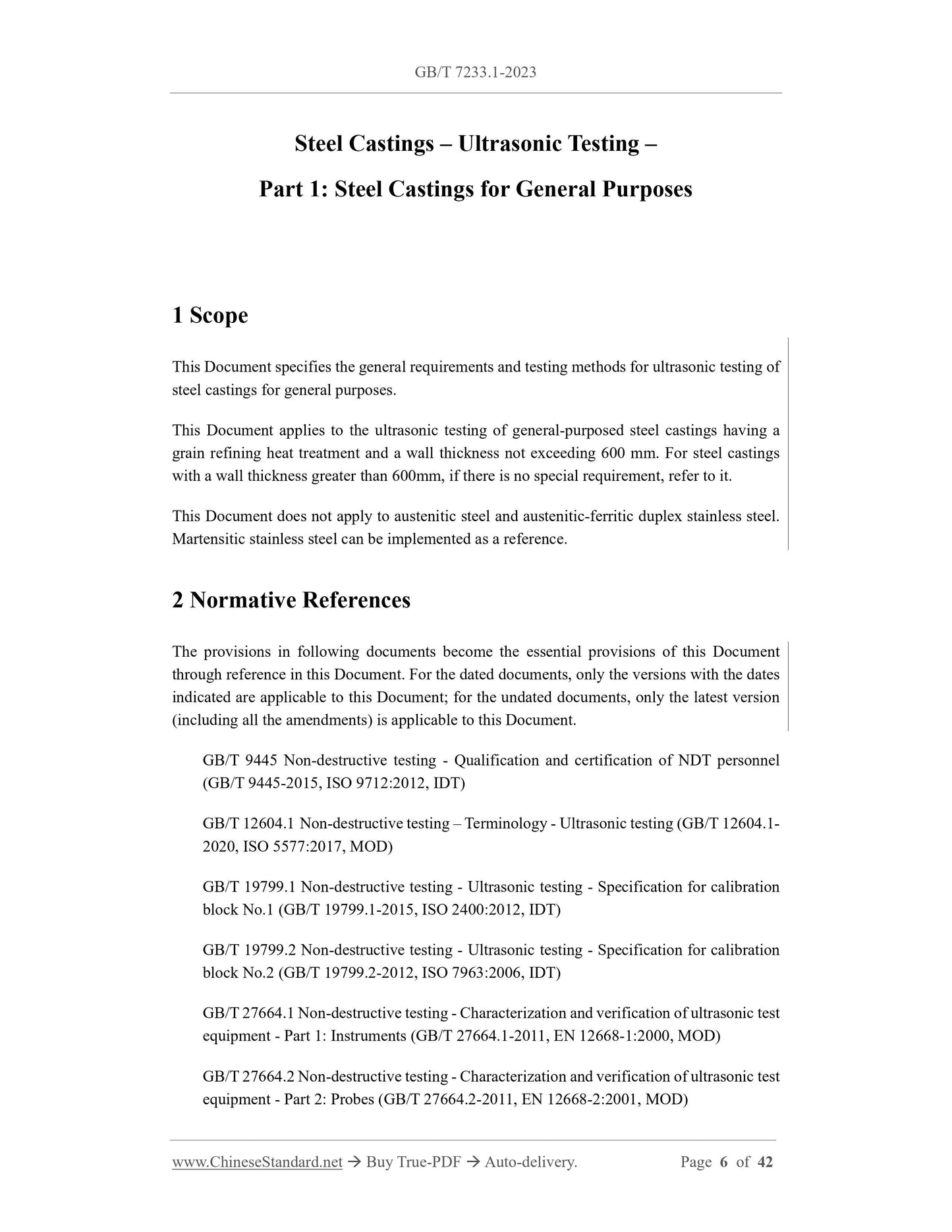
1 Scope
This document specifies the general requirements and testing methods for ultrasonic testing of steel castings for general purposes.
This document applies to the ultrasonic testing of general purpose steel castings that have been heat treated for grain refinement and have a wall thickness not exceeding 600 mm. for the wall
For steel castings with a thickness greater than 600mm, if there is no special requirement, it can be implemented by reference.
This document does not apply to austenitic steel and austenitic-ferritic duplex stainless steel. Martensitic stainless steel can be implemented as a reference.
2 Normative references
The contents of the following documents constitute the essential provisions of this document through normative references in the text. Among them, dated references
For documents, only the version corresponding to the date is applicable to this document; for undated reference documents, the latest version (including all amendments) is applicable to
this document.
GB/T 9445 Qualification and certification of non-destructive testing personnel (GB/T 9445-2015, ISO 9712.2012, IDT)
GB/T 12604.1 Non-destructive testing terminology Ultrasonic testing (GB/T 12064.1-2020, ISO 5577.2017, MOD)
GB/T 19799.1 Nondestructive Testing Ultrasonic Testing No. 1 Calibration Test Block (GB/T 19799.1-2015, ISO 2400.2012,
IDT)
GB/T 19799.2 Nondestructive Testing Ultrasonic Testing No. 2 Calibration Test Block (GB/T 19799.2-2012, ISO 7963.2006,
IDT)
GB/T 27664.1 Performance and inspection of ultrasonic testing equipment for non-destructive testing Part 1.Instruments (GB/T 27664.1-2011,
EN12668-1.2000, MOD)
GB/T 27664.2 Performance and inspection of ultrasonic testing equipment for non-destructive testing Part 2.Probes (GB/T 27664.2-2011,
EN12668-2.2001, MOD)
GB/T 27664.3 Performance and inspection of ultrasonic testing equipment for non-destructive testing - Part 3.Combined equipment (GB/T 27664.3-
2012, EN12668-3.2000, MOD)
GB/T 39239 Characterization and quantification of discontinuities in ultrasonic nondestructive testing (GB/T 39239-2020, ISO 16827.
2012, MOD)
GB/T 39240 General Rules for Nondestructive Testing Ultrasonic Testing (GB/T 39240-2020, ISO 16810.2012, MOD)
GB/T 39242 Ultrasonic testing sensitivity and range setting for non-destructive testing (GB/T 39242-2020, ISO 16811.2012,
MOD)
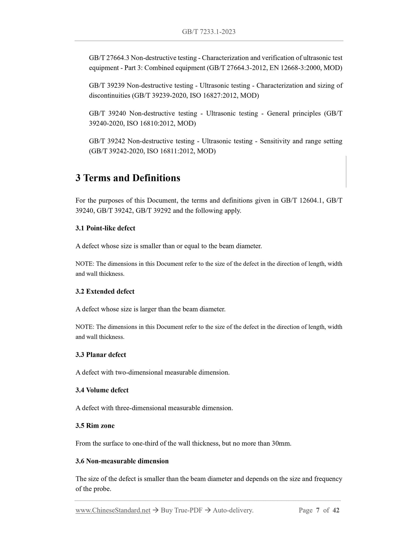
3 Terms and Definitions
GB/T 12604.1, GB/T 39240, GB/T 39242, GB/T 39239 and the following terms and definitions apply to this
document.
4 General requirements
4.1 Ordering information
The buyer should provide the following information when ordering.
a) The area, quantity or proportion of ultrasonic testing of steel castings;
b) The quality grade of each inspection area of the steel casting;
c) Testing process requirements;
d) For additional requirements on the testing process, see 5.5.1.
4.2 Detection range
The most appropriate testing method shall be used to detect all inspected areas of the steel casting (if the shape of the steel casting allows).
4.3 Maximum limits allowed for defects
4.3.1 General principles
A single defect in the inner layer extending to the outer layer shall be assessed as the outer layer defect.
4.3.2 Allowable limits for planar defects whose orientation is mainly perpendicular to the detection surface
4.3.2.1 Figure 1 shows the allowable limits for planar defects.
4.3.2.2 Level 1 should not have defects exceeding ϕ3mmFBH flat-bottomed holes.
4.3.2.3 For defects with a length greater than 10 mm, the maximum size of the defect in the wall thickness direction shall not exceed 10% of the wall thickness. small length
For defects less than 10 mm, the wall thickness direction cannot exceed 25% of the wall thickness.
4.3.2.4 In the direction perpendicular to the test surface or in the transverse direction, the defects whose maximum spacing is not greater than 10mm shall be evaluated as a single defect.
4.3.2.5 For defects whose length is greater than 3mm and whose dimension in the wall thickness direction cannot be measured, the non-measurable dimension shall be identified as 3mm, and the defect shall be
The sink area is calculated according to formula (1).
4.3.3 Permissible limits for volume-type defects
Table 1 gives the allowable limits for volume-type defects, and there should be no defects exceeding any of the specified limits.
4.3.4 The maximum limit of defects allowed by radiographic testing as a supplement to ultrasonic testing
Unless otherwise agreed at the time of ordering, when it is determined that the defect is located in the inner layer after the joint radiographic and ultrasonic inspection is completed, the defect is allowed to be reduced by one grade.
Level, such as radiographic detection level 3 instead of level 2.
4.4 Personnel Qualifications
Ultrasonic testing personnel should obtain corresponding qualification certificates in accordance with GB/T 9445, and can also obtain corresponding qualification certificates in accordance with the provisions of other equivalent accreditation standards.
qualification certificate.
4.5 Wall thickness division
According to the size of steel castings to be assembled (finishing), it is divided into inner layer and outer layer, and the wall thickness division is shown in Figure 2.
a) Flat casting b) Curved casting
4.6 Quality level
If the purchaser has different quality grade requirements for different areas of steel castings, it shall be clearly indicated on the drawing and shall include.
a) all dimensions necessary to accurately locate the inspection area;
b) Preparation of welded areas and special outer layer thicknesses.
Class 1 applies only to prepared weld areas and special outer layers.
Unless otherwise agreed when ordering, the repaired welding area shall be accepted at the same level as the base metal.
5 detection method
5.1 General principles
It should comply with the testing principles stipulated in GB/T 39239, GB/T 39240, GB/T 39242.
5.2 Materials
5.2.1 The ultrasonic detectability of the material is evaluated by comparing the echo height of the reference reflector (usually the first bottom wave) and the noise signal. comment
The price should select a representative area of the steel casting, which represents the surface roughness and maximum thickness range of the workpiece, and should be flat on the upper and lower sides.
OK. According to the reference echo height in Table 2, it should be at least 6dB higher than the noise signal.
5.2.2 At the evaluated maximum thickness, if the echo signal of the smallest detectable flat-bottomed hole or equivalent horizontal hole is less than 6dB higher than the noise signal,
Acoustic detectability does not meet the requirements. In this case, when the signal-to-noise ratio is at least 6dB, the detectable flat-bottomed or transverse hole diameter should be
Indicated in the test report and agreed by both the supplier and the buyer.
5.2.3 The evaluation of the diameter of the flat-bottomed hole can adopt the distance gain size method (DGS) or use the same material and heat treatment condition.
The flat-bottomed hole test block of the state and wall thickness, the diameter of the flat-bottomed hole of the test block can be determined by Table 2 or the equivalent diameter of the horizontal hole.
Formula (2) is used for the diameter conversion of flat-bottomed holes and horizontal holes.
5.3 Equipment and couplant
5.3.1 Instruments and equipment
Ultrasonic instruments should meet the requirements of GB/T 27664.1, and should have the following characteristics.
a) The longitudinal wave and transverse wave in the steel can be continuously selected and adjusted at least within the range of 10mm~2000mm;
b) It should have a continuously adjustable gain above 80dB, the minimum gain step is not greater than 2dB, and the accuracy is ±1dB;
c) The time base linearity error should not be greater than 2%, and the vertical linearity error should not be greater than 5%;
d) reflection method or direct method mode;
e) For single-element and dual-element probes using pulse-echo technology, the nominal frequency is at least applicable to 1MHz~5MHz.
5.3.2 Probes
5.3.2.1 The probe should meet the requirements of GB/T 27664.2, GB/T 27664.3 and meet the following requirements.
a) The nominal frequency should be within the range of 1MHz~5MHz;
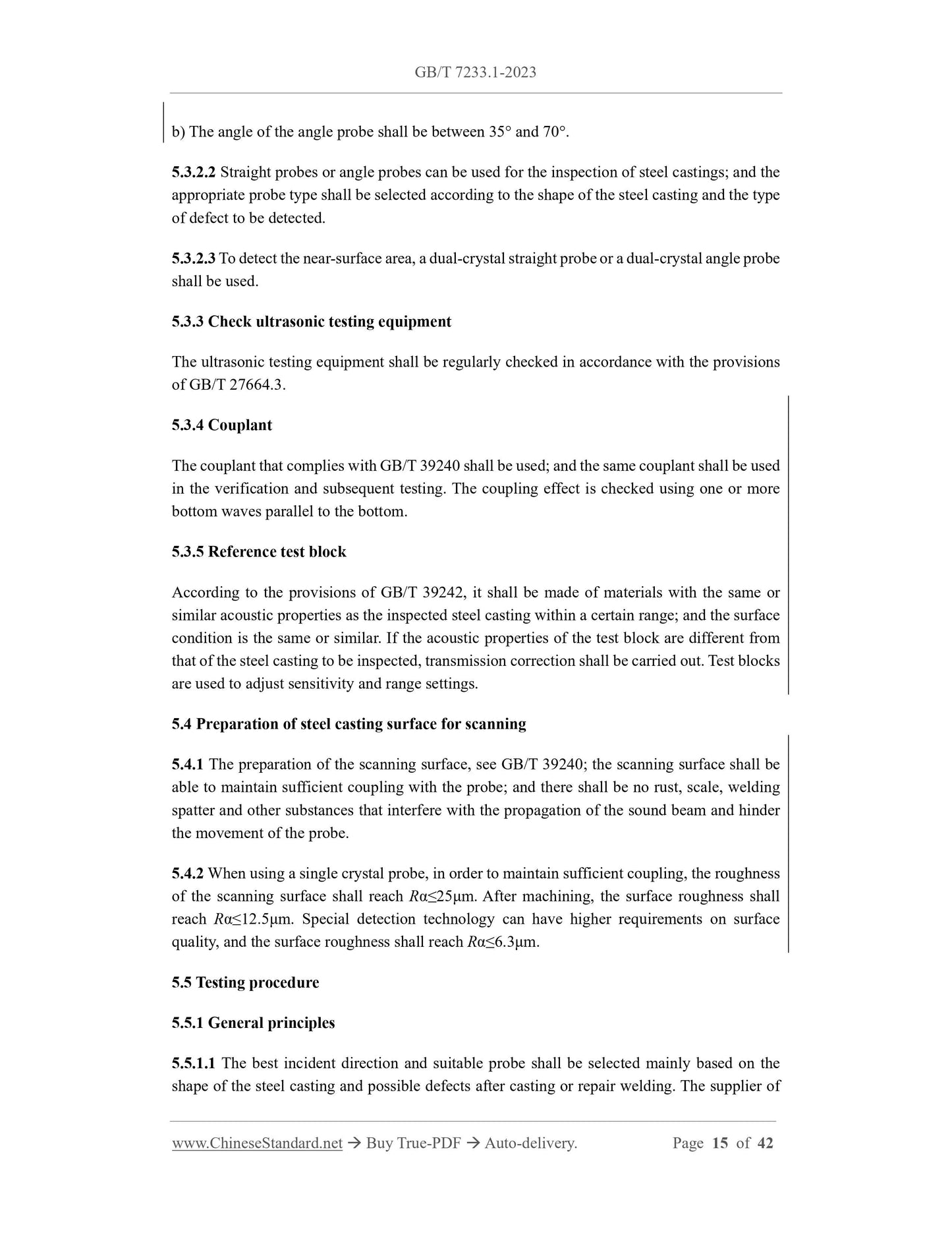
b) The angle of the angled probe should be between 35° and 70°.
5.3.2.2 Straight probes or angled probes can be used for the inspection of steel castings, and the suitable probe type should be based on the shape of the steel casting and the type of defect to be detected
select.
5.3.2.3 To detect the near-surface area, a dual-crystal straight probe or a dual-crystal oblique probe should be used.
5.3.3 Check ultrasonic testing equipment
The ultrasonic testing equipment shall be regularly checked in accordance with the provisions of GB/T 27664.3.
5.3.4 Couplant
The couplant conforming to GB/T 39240 shall be used, and the same couplant shall be used in the verification and subsequent testing. coupling effect
Check with one or more bottom waves parallel to the bottom.
5.3.5 Reference test block
According to the provisions of GB/T 39242, it should be made of materials with the same or similar acoustic properties as the steel castings to be inspected within a specific range, and
And the surface state is the same or similar. If the acoustic properties of the test block are different from those of the steel casting to be inspected, transmission correction shall be carried out. The test block is used to adjust the sensitivity
degree and range settings.
5.4 Preparation of steel casting surface for scanning
5.4.1 The preparation of the scanning surface, see GB/T 39240, the scanning surface should be able to maintain sufficient coupling with the probe, and there should be no rust, scale, welding
Splash and other substances that interfere with the propagation of the sound beam and hinder the movement of the probe.
5.4.2 When using a single crystal probe, in order to maintain sufficient coupling, the roughness of the scanning surface should reach Ra≤25μm. The surface roughness after machining should be
Reach Ra≤12.5μm. Special detection technology can have higher requirements on surface quality, and the surface roughness should reach Ra≤6.3μm.
5.5 Testing procedure
5.5.1 General principles
5.5.1.1 The best incident direction and suitable probe should be selected mainly based on the shape of the steel casting and possible defects after casting or repair welding.
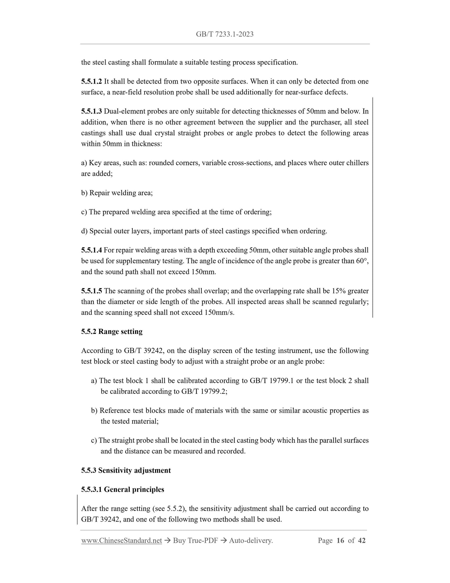
The supplier of steel castings shall formulate appropriate inspection process specifications.
5.5.1.2 It should be detected from two opposite surfaces. When it can only be detected from one surface, a near-surface resolution probe should be used additionally for near-surface defects.
5.5.1.3 Dual-element probes are only suitable for detecting thicknesses of 50mm and below. In addition, when there is no other agreement between the supplier and the buyer, all steel castings shall be
Use a dual crystal straight probe or an angled probe to detect the following areas within 50mm in thickness.
a) Key areas, such as. rounded corners, variable cross-sections, and places where outer chillers are added;
b) repair welding area;
c) The preparation welding area specified at the time of ordering;
d) Special outer layers, important parts of steel castings specified when ordering.
5.5.1.4 For repair welding areas with a depth exceeding 50mm, other suitable angle probes shall be used for supplementary testing. The angle of incidence of the oblique probe is greater than 60°,
The sound path should not exceed 150mm.
5.5.1.5 The scans of the probes should overlap, and the overlap rate should be 15% greater than the diameter or side length of the probes. All inspected areas should be scanned regularly.
The inspection speed should not exceed 150mm/s.
5.5.2 Range setting
According to GB/T 39242, on the display screen of the testing instrument, use the following test block or steel casting body to adjust with a straight probe or an angled probe.
a) The test block 1 shall be calibrated according to GB/T 19799.1 or the test block 2 shall be calibrated according to GB/T 19799.2;
b) Reference test blocks made of materials with the same or similar acoustic properties as the tested material;
c) The straight probe should have parallel surfaces and the distance can be measured and recorded.
5.5.3 Sensitivity adjustment
5.5.3.1 General principles
After the range setting (see 5.5.2), the sensitivity adjustment shall be carried out according to GB/T 39242, and one of the following two methods shall be adopted.
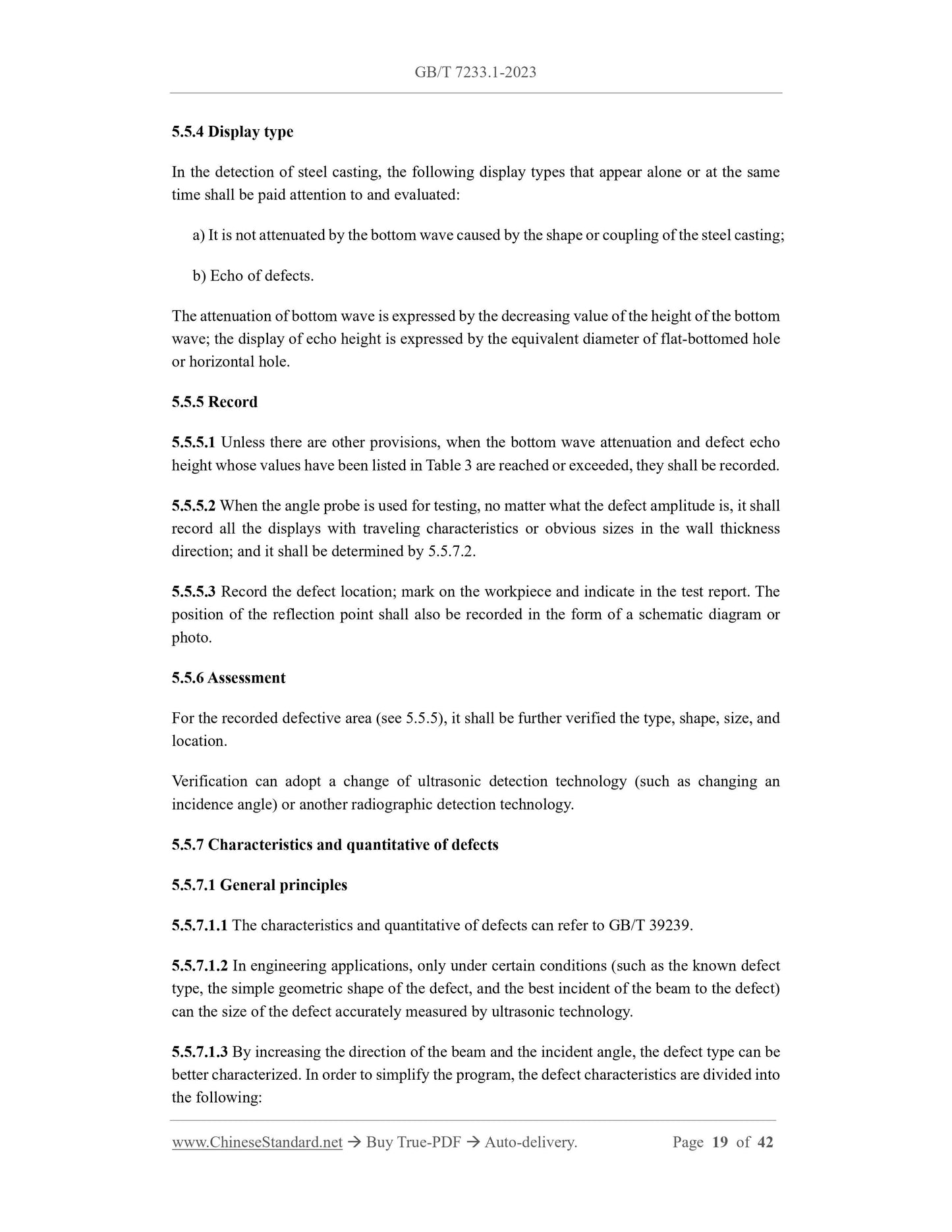
a) Distance amplitude curve method (DAC)
The distance-amplitude curve method is established using the echo heights of a series of identical reflectors (flat-bottomed or horizontal holes) with different sound paths.
b) Distance Gain Size Method (DGS)
The distance gain size method is to use a series of theoretically calculated sound path, instrument gain, flat-bottomed hole diameter perpendicular to the axis of the sound beam
relationship established.
5.5.3.2 Transmission Correction
The transmission correction shall be determined according to GB/T 39242.
When using a reference block, a transmission correction should be made. The transmission correction is related to the roughness of the coupling surface and the roughness of the corresponding surface. if
The corresponding surface is a machined surface or the surface roughness Ra≤12.5μm, which can meet the measurement of transmission correction.
5.5.3.3 Detection of defects
5.5.3.3.1 The gain should be increased appropriately, up to the noise signal visible on the display screen (scanning sensitivity).
5.5.3.3.2 For the diameter of the flat-bottomed hole given in Table 2, within the thickness range to be tested, the echo height should be at least 40% of the screen height.
5.5.3.3.3 During the inspection process, if it is suspe...
View full details