Skip to product information
1 of 9

PayPal, credit cards. Download editable-PDF and invoice in 1 second!

GB/T 6113.104-2016 English PDF (GBT6113.104-2016)

GB/T 6113.104-2016 English PDF (GBT6113.104-2016)

Regular price $610.00 USD
Regular price Sale price $610.00 USD
Sale Sold out
Shipping calculated at checkout.
Delivery: 3 seconds. Download true-PDF + Invoice.Newer version: (Replacing this standard) GB/T 6113.104-2021
Get QUOTATION in 1-minute: Click GB/T 6113.104-2016
Historical versions: GB/T 6113.104-2016
Preview True-PDF (Reload/Scroll if blank)

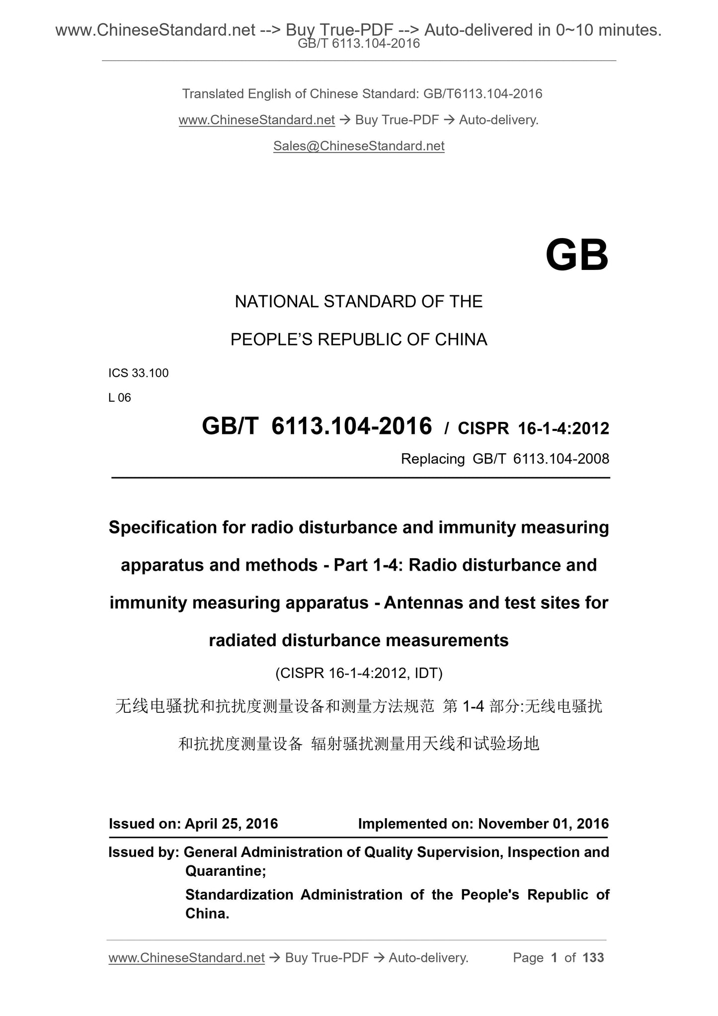
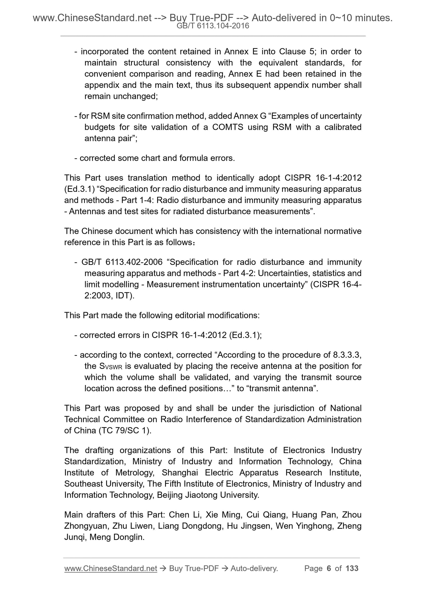
GB/T 6113.104-2016: Specification for radio disturbance and immunity measuring apparatus and methods -- Part 1-4: Radio disturbance and immunity measuring apparatus -- Antennas and test sites for radiated disturbance measurements
GB/T 6113.104-2016
Specification for radio disturbance and immunity measuring apparatus and methods--Part 1-4. Radio disturbance and immunity measuring apparatus--Antennas and test sites for radiated disturbance measurements
ICS 33.100
L06
National Standards of People's Republic of China
Replace GB/T 6113.104-2008
Radio disturbance and immunity measurement equipment and measurements
Method Specification Part 1-4. Radio
Harassment and immunity measurement equipment radiation harassment
Measuring antenna and test site
methods-Part 1-4.Radiodisturbanceandimmunitymeasuringapparatus-
(CISPR16-1-4..2012, IDT)
2016-04-25 released.2016-11-01 implementation
General Administration of Quality Supervision, Inspection and Quarantine of the People's Republic of China
China National Standardization Administration issued
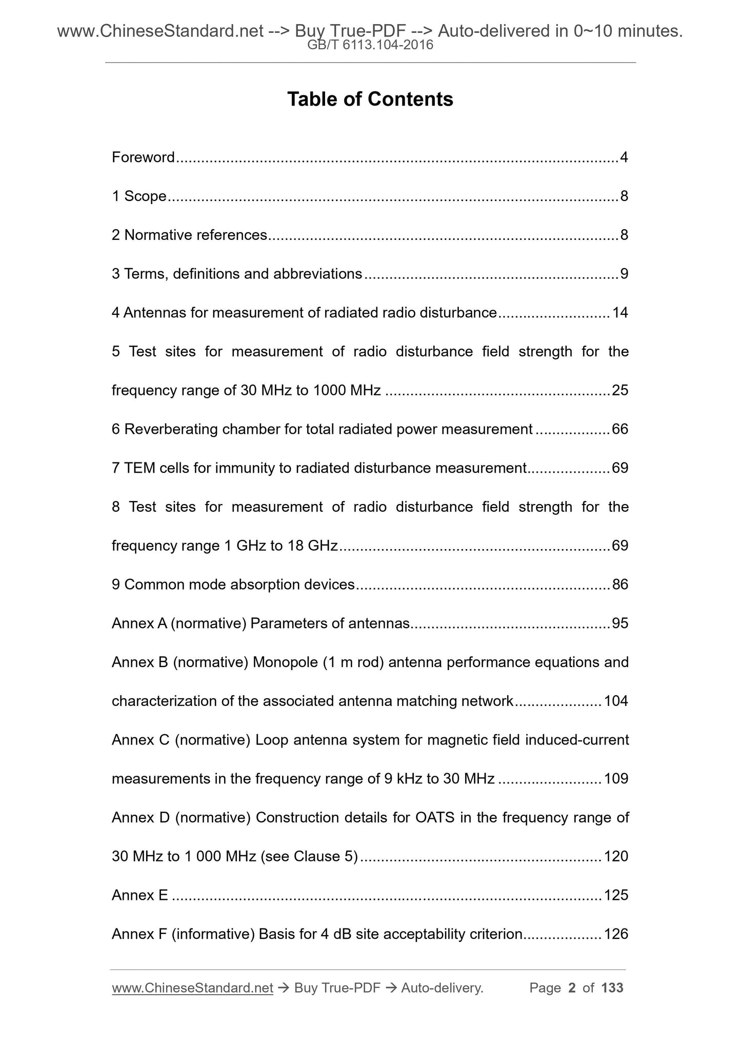
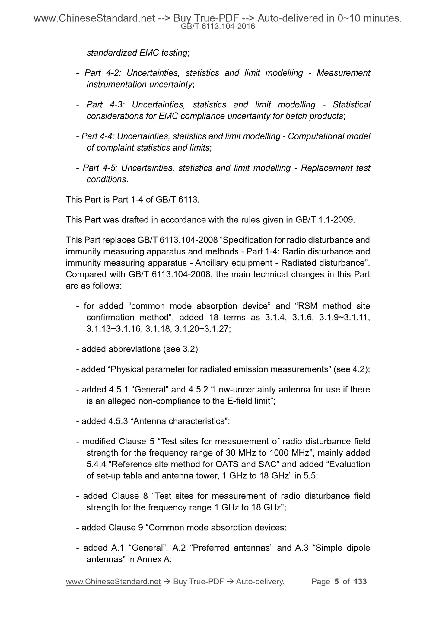
Content
Foreword V
1 range 1
2 Normative references 1
3 Terms, definitions and abbreviations 1
3.1 Terms and Definitions 2
3.2 Abbreviations 5
4 Radio radiation disturbance measurement antenna 5
4.1 Overview 5
4.2 Physical parameters of radiation emission measurements 5
4.3 Frequency range 9kHz~150kHz 6
4.3.1 Overview 6
4.3.2 Magnetic field antenna 6
4.3.3 Shielding of loop antennas 6
4.4 Frequency range 150kHz~30MHz 6
4.4.1 Electric field antenna 6
4.4.2 Magnetic field antenna 6
4.4.3 Symmetry/cross-polarization performance of the antenna 6
4.5 Frequency range 30MHz~1000MHz 7
4.5.1 Overview 7
4.5.2 Use of an antenna with low uncertainty when there is a suspicious condition that does not meet the electric field limit 7
4.5.3 Antenna Characteristics 7
4.5.4 Symmetry of the antenna 9
4.5.5 Antenna cross-polarization performance 10
4.6 Frequency range 1GHz~18GHz 10
4.7 Special Antenna Configuration - Loop Antenna System 10
5 Test site for radio disturbance field strength measurement, 30MHz~1000MHz 11
5.1 Overview 11
5.2 Open test site 11
5.2.1 Overview 11
5.2.2 Climate protection cover 11
5.2.3 Barrier-free area 11
5.2.4 RF environment around the test site 13
5.2.5 Grounding plate 13
5.3 Applicability of other types of test sites 13
5.3.1 Other test sites with grounded plates 13
5.3.2 Test site (FAR) without grounding plate 13
5.4 Test site confirmation 14
5.4.1 Overview 14
5.4.2 Test site validation method overview 14
5.4.3 Site confirmation of OATS and SAC Principles and theoretical values of the NSA method 14
5.4.4 Reference Site Method for OATS and SAC Site Validation 21
5.4.5 Confirming OATS 25 using the NSA method
5.4.6 Confirmation of OATS or SAC with climate protection cover 28
5.4.7 Site confirmation of FAR 30
5.5 Assessment of the impact of the test bench and antenna tower 37
5.5.1 Overview 37
5.5.2 Assessment procedures for the impact of test tables and antenna towers 37
6 Reverberation chamber 39 for total radiant power measurement
6.1 Overview 39
6.2 Cavity 39
6.2.1 Dimensions and Shapes 39
6.2.2 Doors, wall openings and mounting brackets 40
6.2.3 Stirrer 40
6.2.4 Test of agitator efficiency 41
6.2.5 Coupling attenuation 41
7 TEM cell 42 for radiation disturbance immunity measurement
8 Test site for radio disturbance field strength measurement, 1GHz~18GHz 42
8.1 Overview 42
8.2 Reference test site 42
8.3 Confirmation of the test site 42
8.3.1 Overview 42
8.3.2 Acceptance criteria for site confirmation 43
8.3.3 Site Confirmation Method---SVSWR Assessment 43
8.4 Replaceable test site 53
9 common mode absorption device 53
9.1 Overview 53
9.2 S-parameter measurement of CMAD 54
9.3 CMAD test fixture 54
9.4 TRL calibration method 54
9.5 Specification for Clamp Ferrite CMAD 56
9.6 CMAD performance (decrease) verification using spectrum analyzer and tracking generator 57
Appendix A (Normative) Antenna Parameters 59
Appendix B (Normative) The characteristic equation of a monopole antenna (1m rod antenna) and the characteristics of the associated antenna matching network 65
Appendix C (Normative) Loop antenna system for measuring magnetic field induced currents in the frequency range from 9 kHz to 30 MHz 69
Appendix D (Normative) Detailed structure of the OATS ground, frequency range 30MHz~1000MHz (Chapter 5) 78
Appendix E 81
Appendix F (informative) Basis for 4dB Site Acceptance Guidelines 82
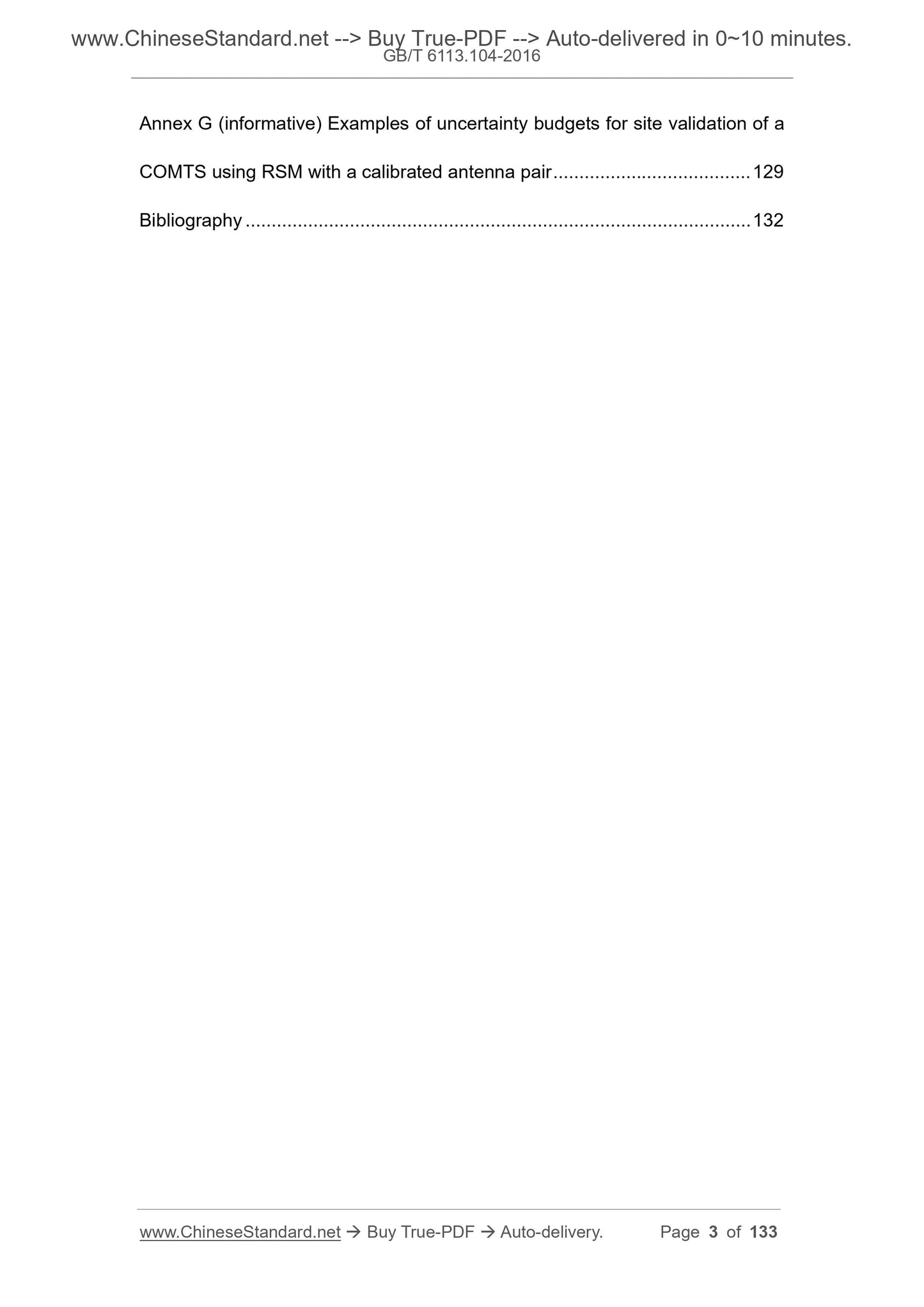
Appendix G (informative) Example of uncertainty budget for the confirmation of the COMTS site by the RSM method 84
Reference 87
Fig.1 Direct wave and ground reflected wave of EUT radiation on the 3m test site (the angle φ from the visual axis of the antenna is half of the lobe width)
Schematic 8 of reaching the LPDA antenna
Figure 2 Schematic diagram of the barrier-free area of the test site equipped with a turntable (see 5.2.3) 12
Figure 3 Schematic diagram of the test site without a turntable and the barrier-free area when the EUT is stationary (see 5.2.3) 12
Fig. 4 Schematic diagram of measurement arrangement of horizontally polarized field attenuation
Figure 5 Schematic diagram of the measurement arrangement of the vertical polarization field attenuation 16
Figure 6 Location of test points at 3m test distance 23
Figure 7 Location of test point pairs for all test distances 24
Figure 8 Example of test point pair selection when the test distance is 10m
Figure 9 Example of studying antenna tower impact AAPR 25
Figure 10 Typical Polarization Locations in OATS or SAC with Climate Protection Covers for Vertical Polarization Confirmation Measurements 29
Figure 11 Horizontal Polarization Confirmation Typical antenna position in OATS or SAC with climate protection cover when measuring 29
Figure 12 Vertical Polarization Confirmation Typical antenna position in OATS or SAC with climate protection cover
(for smaller EUTs) 30
Figure 13 Horizontal Polarization Confirmation Typical antenna position in OATS or SAC with climate protection cover
(for smaller EUTs) 30
Figure 14 Schematic diagram of the measurement position specified by the FAR site confirmation 32
Figure 15 An example of the measurement position and antenna tilt placement specified by the FAR site validation procedure 33
Figure 16 Typical layout of quasi-free space site reference measurements Figure 35
Figure 17 Theoretical values of free-space NSA as a function of frequency for different measured distances [see equation (18)] 37
Figure 18 Schematic diagram of the position of the antenna on the rectangular test table relative to the edge of the test table (top view) 39
Figure 19 Location of the antenna on the test bench (side view) 39
Figure 20 Typical blade agitator example 40
Figure 21 Coupling attenuation with frequency of the reverberation chamber shown in Figure 20 as a function of frequency 41
Figure 22 Example 44 of the E-plane radiation pattern of the transmitting antenna
Figure 23 Radiation pattern of the transmitting antenna H plane 45
Figure 24 SVSWR measurement position point horizontal distribution Figure 46
Figure 25 SVSWR test location point (height requirement) 48
Figure 26 Requirements for conditional test locations 52
Figure 27 Definition of the reference plane in the test fixture 55
Figure 28 Four configurations of TRL calibration 56
Figure 29 Limit value of S11 amplitude measured according to 9.1~9.3
Figure 30 Example of the structure of a 50Ω adapter in the vertical flange of the test fixture 58
Figure 31 Example of a matching network with a balun or transformer 58
Figure 32 Example of a matching adapter with a resistive matching network 58
Figure A...
View full details