GB/T 6113.102-2018 English PDF (GBT6113.102-2018)
Regular price
$940.00 USD
Regular price
Sale price
$940.00 USD
Unit price
/
per
Delivery: 3 seconds. Download true-PDF + Invoice.
Get QUOTATION in 1-minute: Click GB/T 6113.102-2018
Historical versions: GB/T 6113.102-2018
Preview True-PDF (Reload/Scroll if blank)
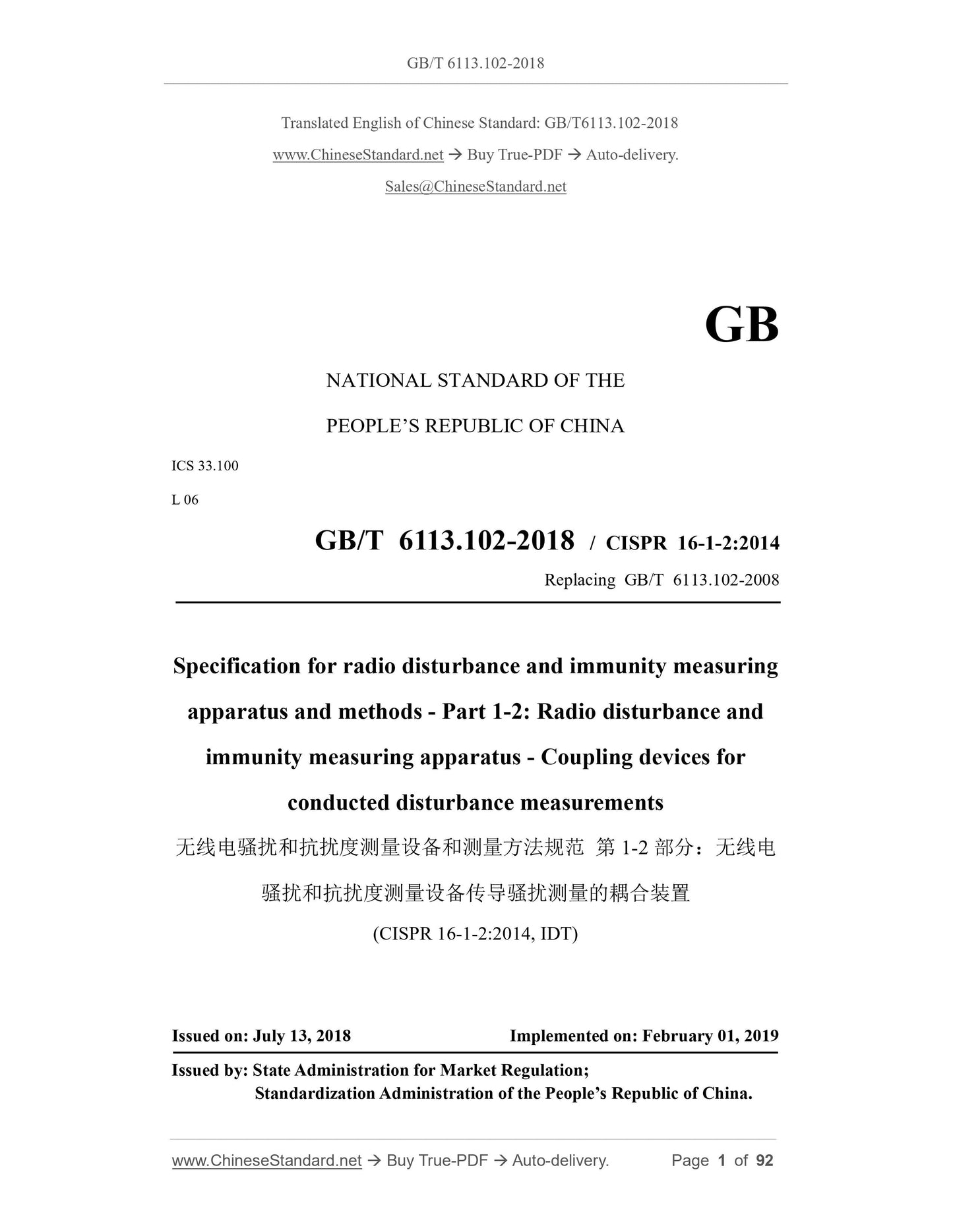
GB/T 6113.102-2018: Specification for radio disturbance and immunity measuring apparatus and methods -- Part 1-2: Radio disturbance and immunity measuring apparatus -- Coupling devices for conducted disturbance measurements
GB/T 6113.102-2018
GB
NATIONAL STANDARD OF THE
PEOPLE’S REPUBLIC OF CHINA
ICS 33.100
L 06
GB/T 6113.102-2018 / CISPR 16-1-2:2014
Replacing GB/T 6113.102-2008
Specification for radio disturbance and immunity measuring
apparatus and methods - Part 1-2: Radio disturbance and
immunity measuring apparatus - Coupling devices for
conducted disturbance measurements
(CISPR 16-1-2:2014, IDT)
ISSUED ON: JULY 13, 2018
IMPLEMENTED ON: FEBRUARY 01, 2019
Issued by: State Administration for Market Regulation;
Standardization Administration of the People’s Republic of China.
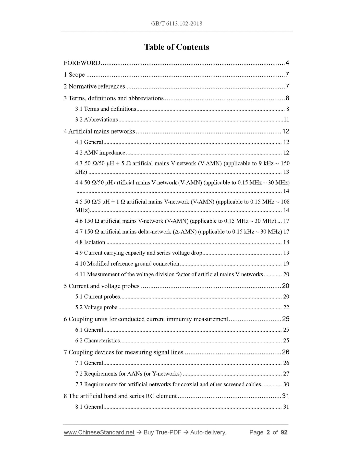
Table of Contents
FOREWORD ... 4
1 Scope ... 7
2 Normative references ... 7
3 Terms, definitions and abbreviations ... 8
3.1 Terms and definitions ... 8
3.2 Abbreviations ... 11
4 Artificial mains networks ... 12
4.1 General ... 12
4.2 AMN impedance ... 12
4.3 50 Ω/50 μH + 5 Ω artificial mains V-network (V-AMN) (applicable to 9 kHz ~ 150
kHz) ... 13
4.4 50 Ω/50 μH artificial mains V-network (V-AMN) (applicable to 0.15 MHz ~ 30 MHz)
... 14
4.5 50 Ω/5 μH + 1 Ω artificial mains V-network (V-AMN) (applicable to 0.15 MHz ~ 108
MHz) ... 14
4.6 150 Ω artificial mains V-network (V-AMN) (applicable to 0.15 MHz ~ 30 MHz) ... 17
4.7 150 Ω artificial mains delta-network (Δ-AMN) (applicable to 0.15 kHz ~ 30 MHz) 17
4.8 Isolation ... 18
4.9 Current carrying capacity and series voltage drop ... 19
4.10 Modified reference ground connection ... 19
4.11 Measurement of the voltage division factor of artificial mains V-networks ... 20
5 Current and voltage probes ... 20
5.1 Current probes ... 20
5.2 Voltage probe ... 22
6 Coupling units for conducted current immunity measurement ... 25
6.1 General ... 25
6.2 Characteristics ... 25
7 Coupling devices for measuring signal lines ... 26
7.1 General ... 26
7.2 Requirements for AANs (or Y-networks) ... 27
7.3 Requirements for artificial networks for coaxial and other screened cables... 30
8 The artificial hand and series RC element ... 31
8.1 General ... 31
8.2 Construction of the artificial hand and RC element ... 31
8.3 The use of the artificial hand... 32
9 CDNE for measurement of disturbance voltage in frequency range 30 MHz ~ 300
MHz ... 35
9.1 Instrumentation ... 35
9.2 Technical requirements for the CDNE-X ... 36
9.3 Technical requirement for the RGP ... 41
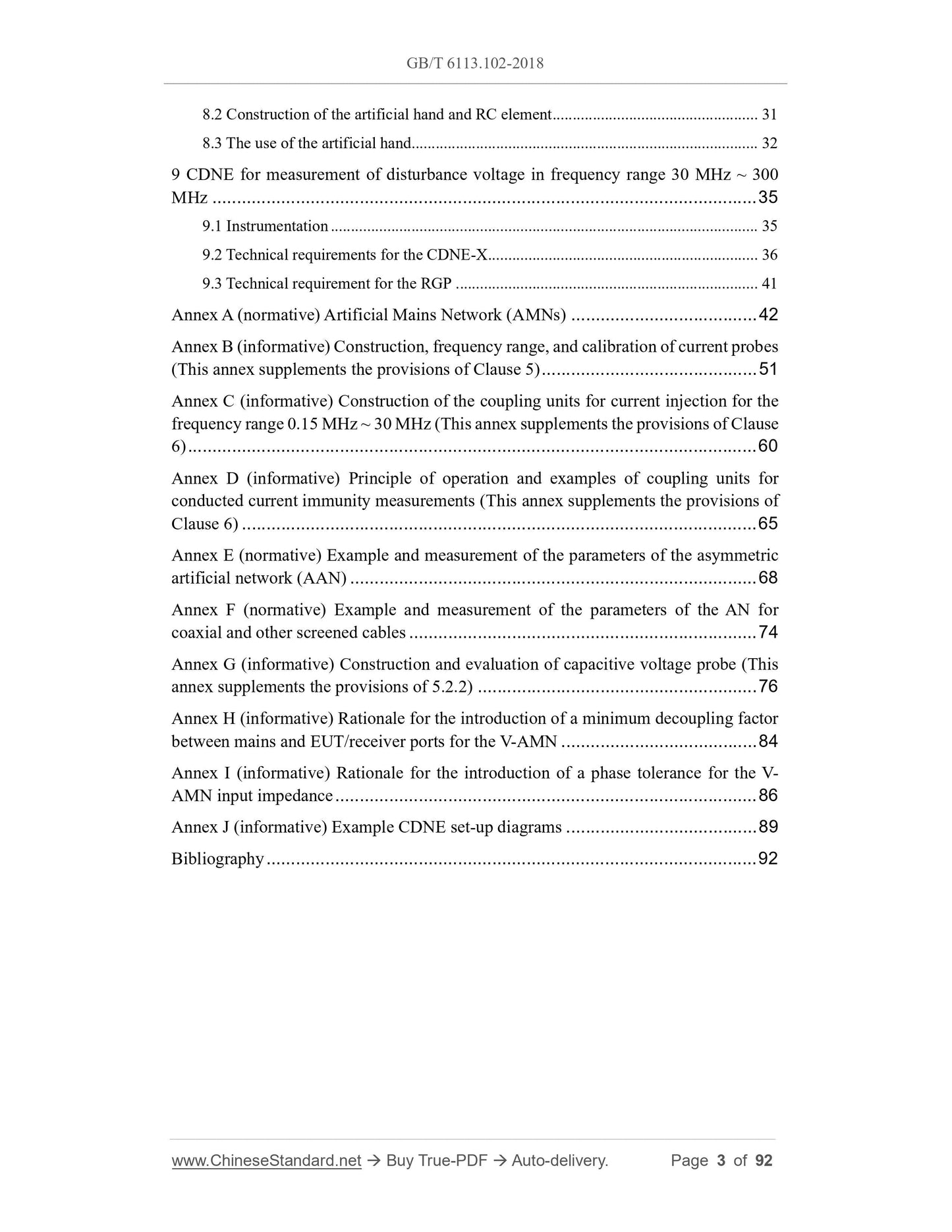
Annex A (normative) Artificial Mains Network (AMNs) ... 42
Annex B (informative) Construction, frequency range, and calibration of current probes
(This annex supplements the provisions of Clause 5) ... 51
Annex C (informative) Construction of the coupling units for current injection for the
frequency range 0.15 MHz ~ 30 MHz (This annex supplements the provisions of Clause
6) ... 60
Annex D (informative) Principle of operation and examples of coupling units for
conducted current immunity measurements (This annex supplements the provisions of
Clause 6) ... 65
Annex E (normative) Example and measurement of the parameters of the asymmetric
artificial network (AAN) ... 68
Annex F (normative) Example and measurement of the parameters of the AN for
coaxial and other screened cables ... 74
Annex G (informative) Construction and evaluation of capacitive voltage probe (This
annex supplements the provisions of 5.2.2) ... 76
Annex H (informative) Rationale for the introduction of a minimum decoupling factor
between mains and EUT/receiver ports for the V-AMN ... 84
Annex I (informative) Rationale for the introduction of a phase tolerance for the V-
AMN input impedance ... 86
Annex J (informative) Example CDNE set-up diagrams ... 89
Bibliography ... 92
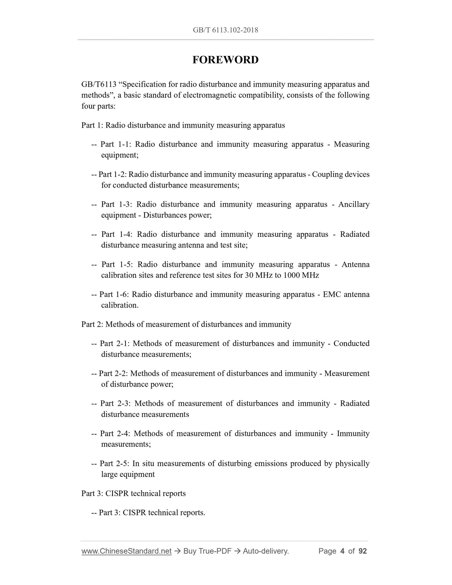
FOREWORD
GB/T6113 “Specification for radio disturbance and immunity measuring apparatus and
methods”, a basic standard of electromagnetic compatibility, consists of the following
four parts:
Part 1: Radio disturbance and immunity measuring apparatus
-- Part 1-1: Radio disturbance and immunity measuring apparatus - Measuring
equipment;
-- Part 1-2: Radio disturbance and immunity measuring apparatus - Coupling devices
for conducted disturbance measurements;
-- Part 1-3: Radio disturbance and immunity measuring apparatus - Ancillary
equipment - Disturbances power;
-- Part 1-4: Radio disturbance and immunity measuring apparatus - Radiated
disturbance measuring antenna and test site;
-- Part 1-5: Radio disturbance and immunity measuring apparatus - Antenna
calibration sites and reference test sites for 30 MHz to 1000 MHz
-- Part 1-6: Radio disturbance and immunity measuring apparatus - EMC antenna
calibration.
Part 2: Methods of measurement of disturbances and immunity
-- Part 2-1: Methods of measurement of disturbances and immunity - Conducted
disturbance measurements;
-- Part 2-2: Methods of measurement of disturbances and immunity - Measurement
of disturbance power;
-- Part 2-3: Methods of measurement of disturbances and immunity - Radiated
disturbance measurements
-- Part 2-4: Methods of measurement of disturbances and immunity - Immunity
measurements;
-- Part 2-5: In situ measurements of disturbing emissions produced by physically
large equipment
Part 3: CISPR technical reports
-- Part 3: CISPR technical reports.
Part 4: Uncertainties, statistics and limit modelling
-- Part 4-1: Uncertainties, statistics and limit modelling - Uncertainties in
standardized EMC tests;
-- Part 4-2: Uncertainties, statistics and limit modelling - Measurement
instrumentation uncertainty;
-- Part 4-3: Uncertainties, statistics and limit modelling - Statistical considerations
in the determination of EMC compliance of mass-produced products;
-- Part 4-4: Uncertainties, statistics and limit modelling - Statistics of complaints and
a model for the calculation of limits;
-- Part 4-5: Uncertainties, statistics and limit modelling - Conditions for the use of
alternative test methods.
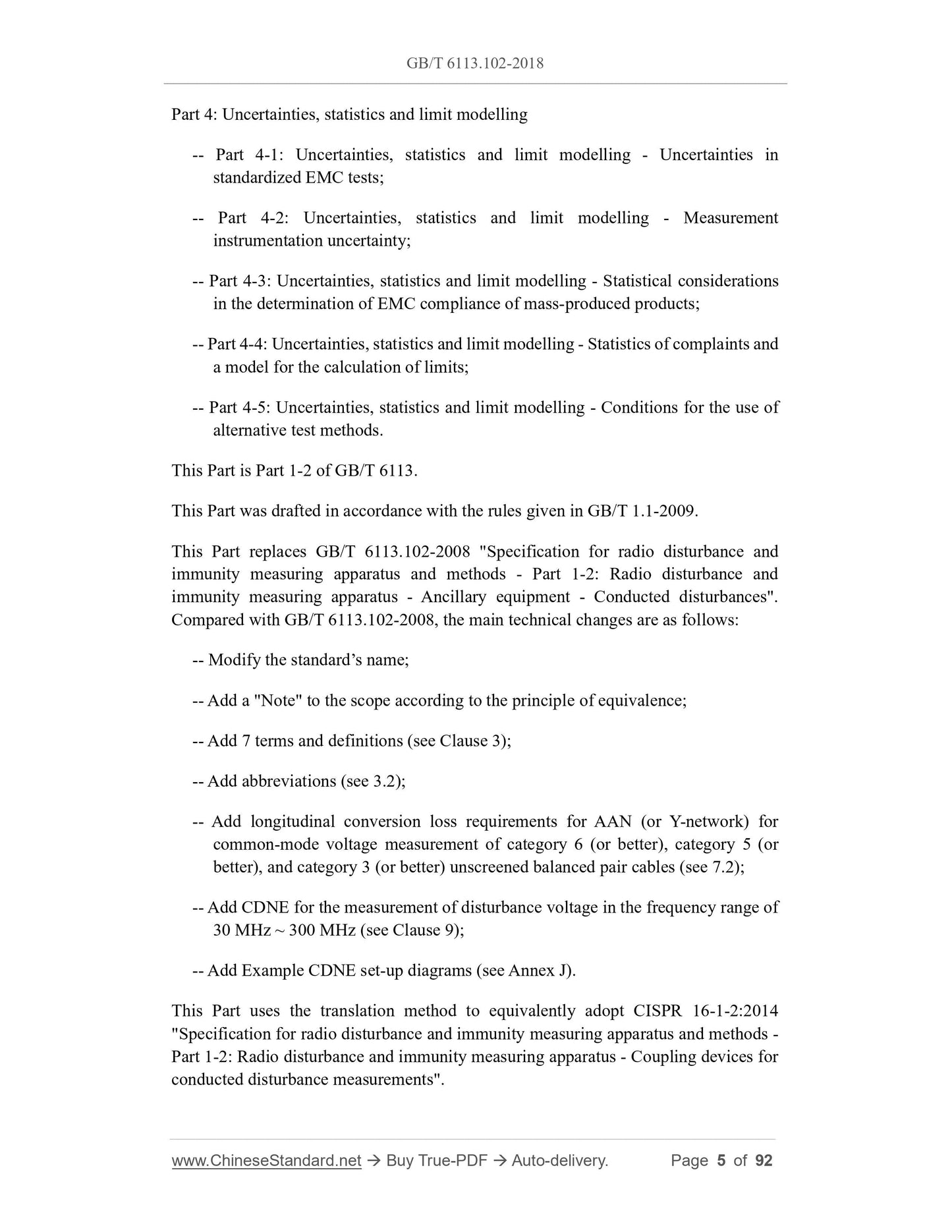
This Part is Part 1-2 of GB/T 6113.
This Part was drafted in accordance with the rules given in GB/T 1.1-2009.
This Part replaces GB/T 6113.102-2008 "Specification for radio disturbance and
immunity measuring apparatus and methods - Part 1-2: Radio disturbance and
immunity measuring apparatus - Ancillary equipment - Conducted disturbances".
Compared with GB/T 6113.102-2008, the main technical changes are as follows:
-- Modify the standard’s name;
-- Add a "Note" to the scope according to the principle of equivalence;
-- Add 7 terms and definitions (see Clause 3);
-- Add abbreviations (see 3.2);
-- Add longitudinal conversion loss requirements for AAN (or Y-network) for
common-mode voltage measurement of category 6 (or better), category 5 (or
better), and category 3 (or better) unscreened balanced pair cables (see 7.2);
-- Add CDNE for the measurement of disturbance voltage in the frequency range of
30 MHz ~ 300 MHz (see Clause 9);
-- Add Example CDNE set-up diagrams (see Annex J).
This Part uses the translation method to equivalently adopt CISPR 16-1-2:2014
"Specification for radio disturbance and immunity measuring apparatus and methods -
Part 1-2: Radio disturbance and immunity measuring apparatus - Coupling devices for
conducted disturbance measurements".
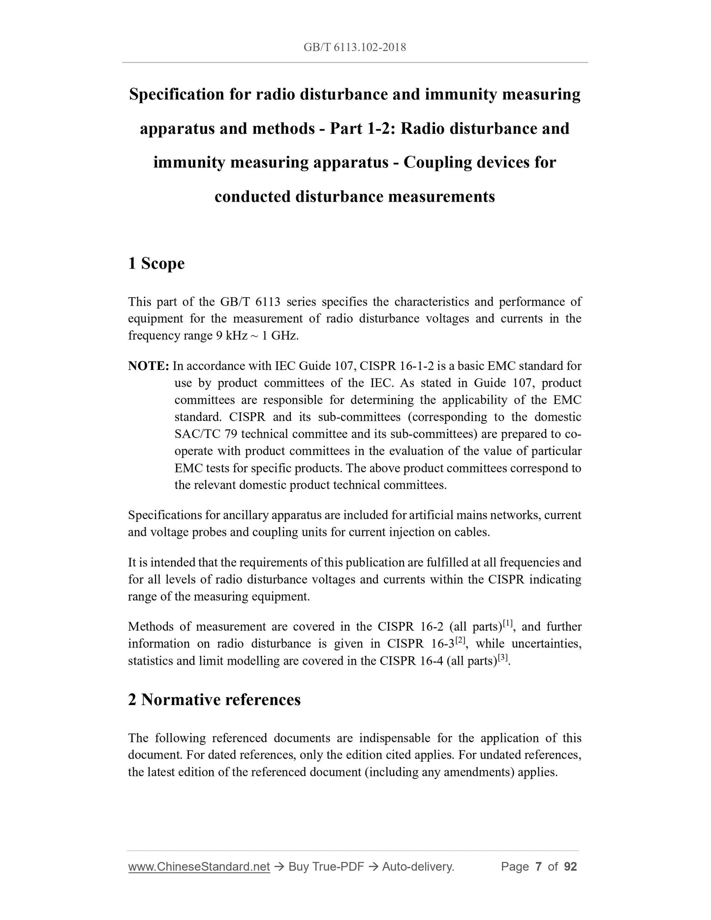
Specification for radio disturbance and immunity measuring
apparatus and methods - Part 1-2: Radio disturbance and
immunity measuring apparatus - Coupling devices for
conducted disturbance measurements
1 Scope
This part of the GB/T 6113 series specifies the cha...