1
/
of
6
www.ChineseStandard.us -- Field Test Asia Pte. Ltd.
GB/T 5597-1999 English PDF (GB/T5597-1999)
GB/T 5597-1999 English PDF (GB/T5597-1999)
Regular price
$170.00
Regular price
Sale price
$170.00
Unit price
/
per
Shipping calculated at checkout.
Couldn't load pickup availability
GB/T 5597-1999: Test method for complex permittivity of solid dielectric materials at microwave frequencies
Delivery: 9 seconds. Download (and Email) true-PDF + Invoice.Get Quotation: Click GB/T 5597-1999 (Self-service in 1-minute)
Newer / historical versions: GB/T 5597-1999
Preview True-PDF
Scope
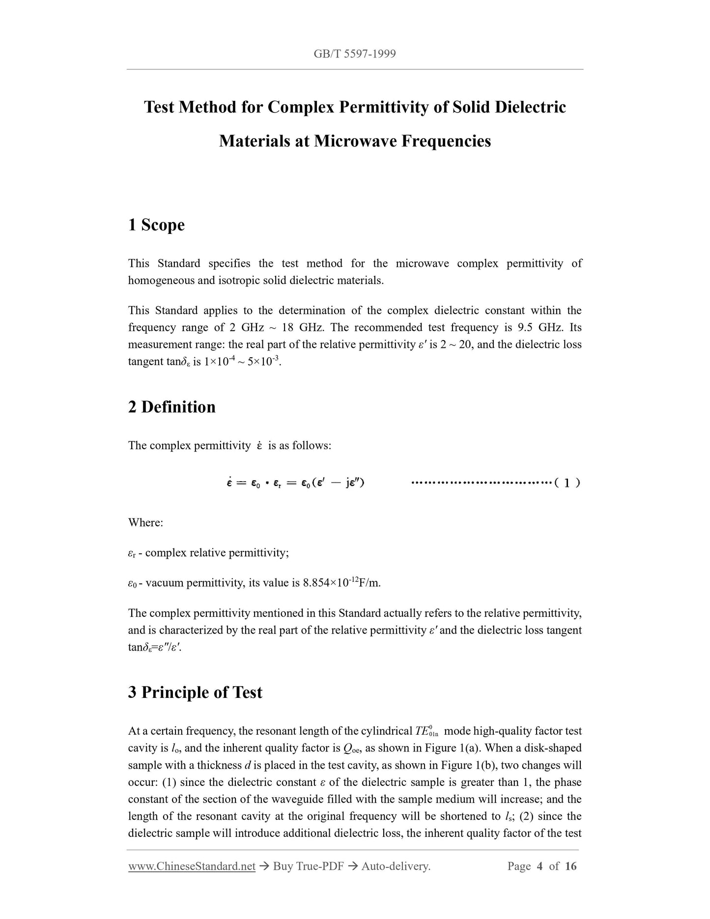
This Standard specifies the test method for the microwave complex permittivity ofhomogeneous and isotropic solid dielectric materials.
This Standard applies to the determination of the complex dielectric constant within the
frequency range of 2 GHz ~ 18 GHz. The recommended test frequency is 9.5 GHz. Its
measurement range: the real part of the relative permittivity ε' is 2 ~ 20, and the dielectric loss
tangent tanδε is 1×10⁻⁴ ~ 5×10⁻³.
Basic Data
| Standard ID | GB/T 5597-1999 (GB/T5597-1999) |
| Description (Translated English) | Test method for complex permittivity of solid dielectric materials at microwave frequencies |
| Sector / Industry | National Standard (Recommended) |
| Classification of Chinese Standard | L90 |
| Classification of International Standard | 31.03 |
| Word Count Estimation | 10,131 |
| Date of Issue | 5/19/1999 |
| Date of Implementation | 12/1/1999 |
| Older Standard (superseded by this standard) | GB/T 5597-1985 |
| Issuing agency(ies) | State Quality and Technical Supervision |
| Summary | This standard specifies uniform test methods isotropic solid dielectric material microwave complex permittivity. |
Share