www.ChineseStandard.us -- Field Test Asia Pte. Ltd.
GB/T 5099.3-2017: Seamless steel gas cylinders -- Part 3: Normalized cylinders
Delivery: 9 seconds. Download (and Email) true-PDF + Invoice.
Get Quotation: Click
GB/T 5099.3-2017 (Self-service in 1-minute)
Newer / historical versions: GB/T 5099.3-2017Preview True-PDF
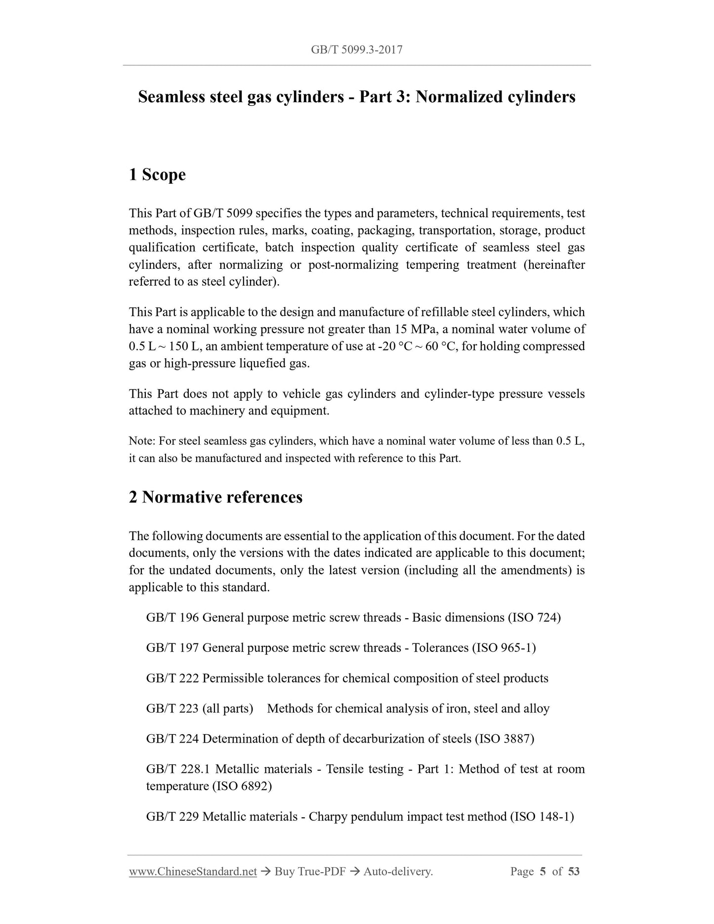
Scope
This Part of GB/T 5099 specifies the types and parameters, technical requirements, test
methods, inspection rules, marks, coating, packaging, transportation, storage, product
qualification certificate, batch inspection quality certificate of seamless steel gas
cylinders, after normalizing or post-normalizing tempering treatment (hereinafter
referred to as steel cylinder).
This Part is applicable to the design and manufacture of refillable steel cylinders, which
have a nominal working pressure not greater than 15 MPa, a nominal water volume of
0.5 L ~ 150 L, an ambient temperature of use at -20 °C ~ 60 °C, for holding compressed
gas or high-pressure liquefied gas.
This Part does not apply to vehicle gas cylinders and cylinder-type pressure vessels
attached to machinery and equipment.
Note: For steel seamless gas cylinders, which have a nominal water volume of less than 0.5 L,
it can also be manufactured and inspected with reference to this Part.
Basic Data
| Standard ID | GB/T 5099.3-2017 (GB/T5099.3-2017) |
| Description (Translated English) | Seamless steel gas cylinders -- Part 3: Normalized cylinders |
| Sector / Industry | National Standard (Recommended) |
| Classification of Chinese Standard | J74 |
| Classification of International Standard | 23.020.30 |
| Word Count Estimation | 38,327 |
| Date of Issue | 2017-12-29 |
| Date of Implementation | 2019-01-01 |
| Issuing agency(ies) | General Administration of Quality Supervision, Inspection and Quarantine of the People's Republic of China, Standardization Administration of the People's Republic of China |