1
/
of
6
PayPal, credit cards. Download editable-PDF and invoice in 1 second!
GB/T 5013.1-2008 English PDF (GB/T5013.1-2008)
Regular price
$85.00 USD
Regular price
Sale price
$85.00 USD
Unit price
/
per
Shipping calculated at checkout.
Couldn't load pickup availability
Delivery: 3 seconds. Download true-PDF + Invoice.
Get Quotation: Click GB/T 5013.1-2008 (Self-service in 1-minute)
Historical versions (Master-website): GB/T 5013.1-2008
Preview True-PDF (Reload/Scroll-down if blank)
GB/T 5013.1-2008: Rubber insulated cables of rated voltages up to and including 450/750 V -- Part 1: General requirements
GB/T 5013.1-2008
Rubber insulated cables of rated voltages up to and including 450/750 V. Part 1. General requiremnts
ICS 29.060.20
K13
National Standards of People's Republic of China
GB/T 5013.1-2008/IEC 60245-1..2003
Replacing GB 5013.1-1997
Rated voltage 450/750 犞 and below rubber insulated cables
Part 1. general requirements
(IEC 60245-1..2003, IDT)
Posted.2008-01-22
2008-09-01 implementation
General Administration of Quality Supervision, Inspection and Quarantine of People's Republic of China
China National Standardization Administration released
Foreword
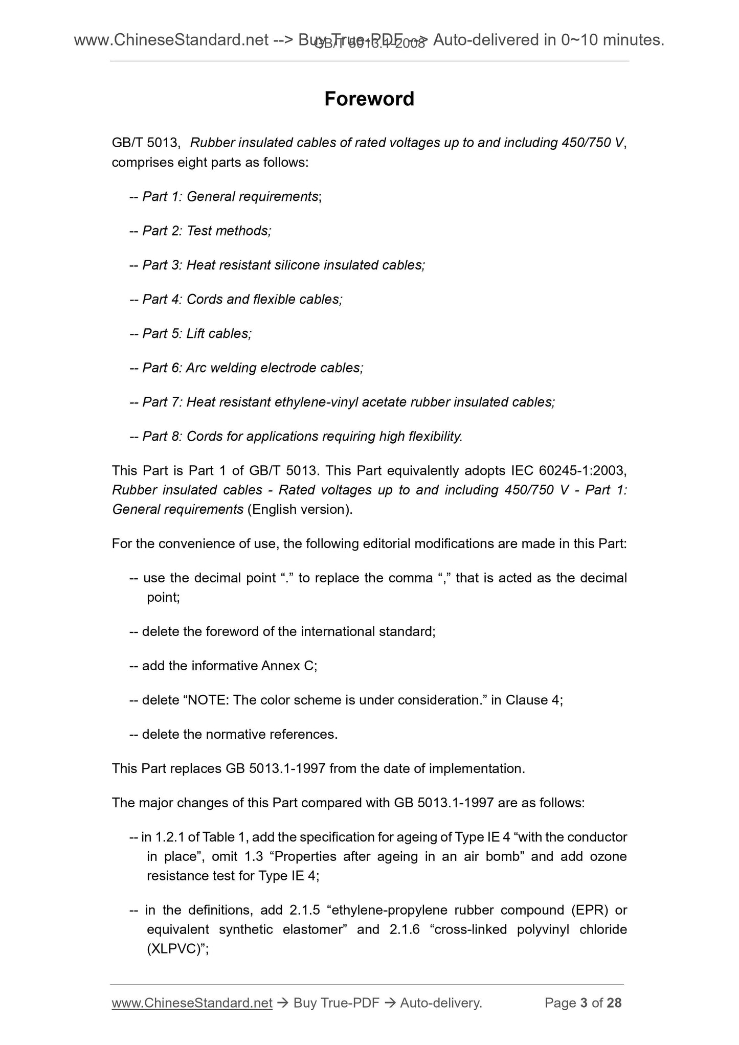
GB/T 5013 "rated voltage 450/750V and below rubber insulated cables" is divided into eight sections.
--- Part 1. General requirements;
--- Part 2. Test methods;
--- Part 3. Heat-resistant silicone rubber insulated cables;
--- Part 4. Cords and flexible cables;
--- Part 5. elevator cables;
--- Part 6. welding machine cables;
--- Part 7. Heat-resistant vinyl - vinyl acetate rubber insulated cables;
--- Part 8. Special soft wire.
This section GB/T 5013 Part 1. This section identical with IEC 60245-1..2003 "rated voltage 450/750V and
Lower rubber insulated cables - Part 1. General requirements "(English version).
For ease of use, this part of GB/T 5013 made the following editorial changes.
--- Use the decimal point "." Instead of as a decimal point comma ",";
--- Remove the foreword of the international standard;
--- Increased information appendix C;
--- Removed the "NOTEThecolourschemeisunderconsideration." In Chapter 4;
--- Removed references.
This section from the date of implementation instead of GB 5013.1-1997.
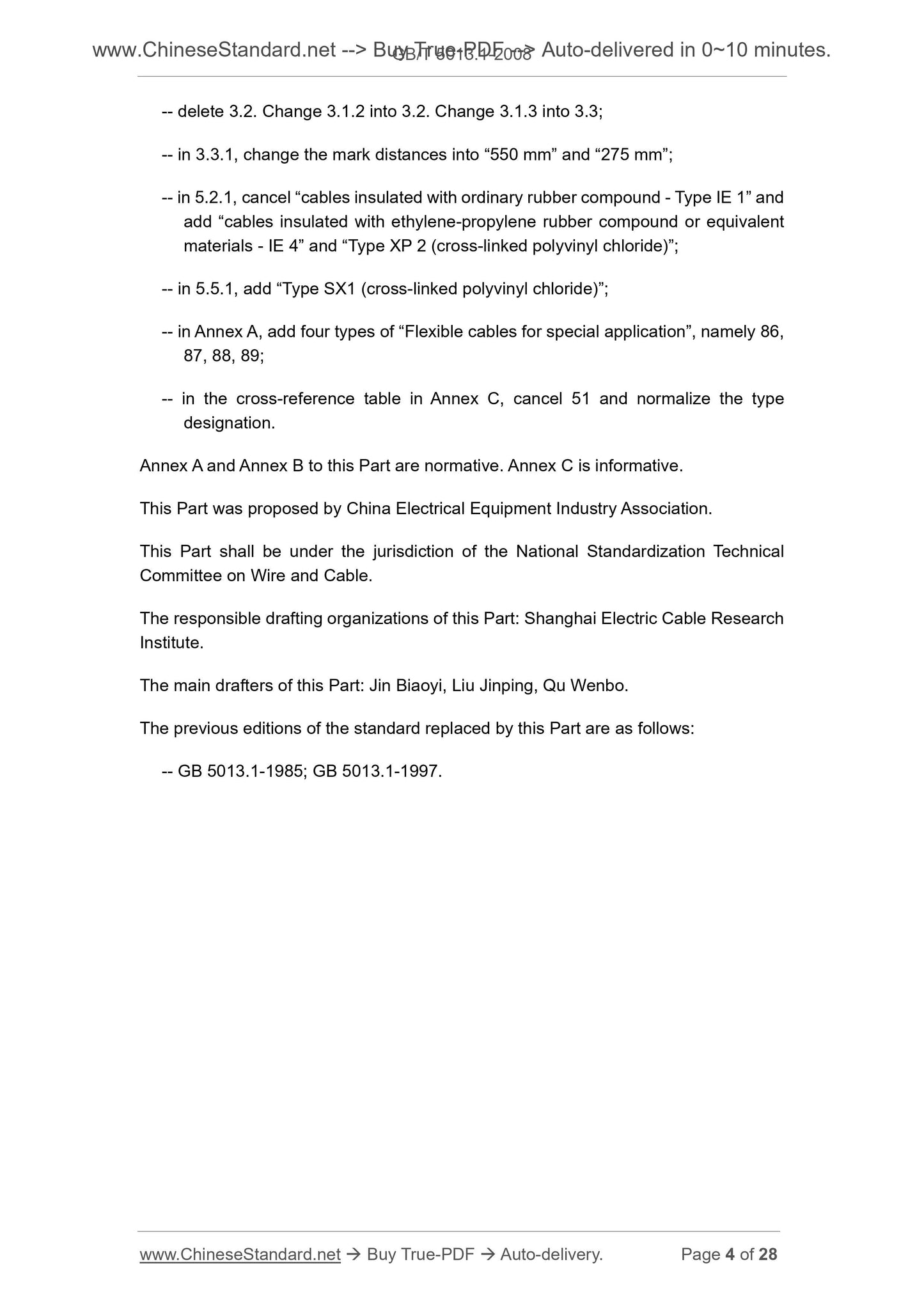
This section compared with GB 5013.1-1997 main changes are as follows.
--- Table 1 1.2.1 in IE4 insulation aging provisions should be with the conductor, 1.3 "oxygen bomb after aging performance" omitted, the insulation on the IE4 increased 4
"Ozone resistance test";
--- Increasing the definition 2.1.5 "Ethylene Propylene rubber mixture or other equivalent synthetic elastomer" and 2.1.6 "cross-linked polyvinyl chloride";
--- Removed 3.2; 3.1.2 changed to 3.2, 3.1.3 changed to 3.3;
--- 3.3.1 in the sign distance to "550mm" and "275mm";
--- 5.2.1 canceled the "ordinary rubber compound insulated cable --- IE1 type", an increase of "EPDM rubber mixture or its equivalent
Material insulated cable --- IE4 type "and" XP1 type (cross-linked polyvinyl chloride) ";
--- 5.5.1 added "SX1 type (cross-linked polyvinyl chloride)";
--- Appendix A "special purpose flexible cable" an increase of 86,87,88,89 four models;
--- Appendix C model reference table was canceled 51, while the preparation of the model specifications.
This part of the Appendix A and Appendix B normative appendix, Appendix C is an informative annex.
This part is proposed by China Electrical Equipment Industry Association.
This part of the national wire and cable standardization Technical Committee.
This section is responsible for drafting unit. Shanghai Electric Cable Research Institute.
The main drafters of this section. gold standard, Liu Jingping, Qu Wenbo.
This part of the standard replaces the previous editions are. GB 5013.1-1985, GB 5013.1-1997.
GB/T 5013.1-2008/IEC 60245-1..2003
Rated voltage 450/750 犞 and below rubber insulated cables
Part 1. general requirements
1 Overview
1.1 range
GB/T 5013 This section applies to the rated voltage U0/U 450/750V and below, vulcanized rubber insulation and sheath (if any)
Hard and soft cables for the exchange of rated voltage not exceeding 450/750V power plant.
NOTE. The term "flexible cord" is used for some models of flexible cables.
Various types of cables in GB/T 5013.3, GB/T 5013.4 and other parts of the provisions of the cable model representation in Appendix A.
GB/T 5013 Test methods specified in parts 1 to 8 see GB/T 5013.2, GB/T 18380.1 and GB/T 2951
Related parts.
1.2 Normative references
The following documents contain provisions which, through reference in this part of GB/T 5013, become the provisions of this section. Any reference to the date of the citation
All subsequent amendments (not including errata content) or revisions do not apply to this section, however, encouraged to be reached under this section
The parties to the agreement study whether the latest versions of these documents are available. For undated references, the latest version applies to this book
section.
GB/T 2951.1-1997 Common test methods for cable insulation and sheathing materials - Part 1. Common test methods Section 1. Thickness
Measurement of dimensions and dimensions --- Mechanical test (idt IEC 60811-1-1..1993)
GB/T 2951.2-1997 Common test methods for insulating and sheathing materials of cables Part 1. Common test methods Section 2. Heat
Aging test method (idt IEC 60811-1-2. 1985)
GB/T 2951.4-1997 Common test methods for cable insulation and sheathing materials - Part 1. Common test methods Section 4. Low
Temperature test method (idt IEC 60811-1-4. 1985)
GB/T 2951.5-1997 Common test methods for insulating and sheathing materials of cables - Part 2. Special test methods for elastomeric compounds
Method 1. Ozone resistance test --- Thermal elongation test --- Immersed mineral oil test (idt IEC 60811-2-1. 1986)
GB/T 2951.6-1997 General test methods for insulating and sheathing materials of cables - Part 3. Specific tests for PVC compounds
Methods Section 1. High Temperature Pressure Test --- Cracking Resistance Test (IEC 60811-3-1. 1985, IDT)
GB/T 3956 cable conductor (GB/T 3956-1997, idt IEC 60228. 1978)
GB/T 5013.2-2008 Rubber insulated cables of rated voltages up to and including 450/750V - Part 2. Test methods (IEC 60245-2.
1998, IDT)
GB/T 5013.3 Rated voltage 450/750V and below rubber insulated cables - Part 3. Heat-resistant silicone rubber insulated cables
(GB/T 5013.3-2008, IEC 60245-3..1994, IDT)
GB/T 5013.4 Rated voltage 450/750 V and below rubber insulated cables - Part 4. Cords and flexible cables
(GB/T 5013.4-2008, IEC 60245-4..2004, IDT)
GB/T 5013.7-2008 Rated voltage 450/750V and below rubber insulated cables - Part 7. Heat-resistant ethylene - vinyl acetate
Ester rubber insulated cable (IEC 60245-7..1994, IDT)
GB/T 18380.1 burning test of cables under fire conditions - Part 1. Vertical burning test of single insulated wire or cable
Methods (GB/T 18380.1-2001, IEC 60332-1..1993, IDT)
2 Terms and definitions
The following terms and definitions apply to GB/T 5013 parts.
GB/T 5013.1-2008/IEC 60245-1..2003
2.1 Insulation and sheathing material definition
2.1.1
The mixture is classified according to the measured properties of the prescribed test.
Note. The model number is not directly related to the composition of the mixture.
2.1.2
Eraser blends are properly selected, formulated, processed and vulcanized, and its unique components are rubber and/or synthetic elastomer blends.
Note. Vulcanization refers to the next process of insulation and/or sheath extrusion, in order to permanently crosslink the elastomer.
2.1.3
Elastomers of vulcanized mixtures are neoprene or other comparable synthetic elastomers that behave like PCP.
2.1.4
The elastomers of the crosslinking mixture are ethylene-vinyl acetate or other comparable synthetic elastomers similar in performance to EVA.
2.1.5
The elastomer of the crosslinking mixture is ethylene-propylene rubber or other comparable synthetic elastomer with properties similar to those of EPR.
2.1.6
The appropriate choice, proportioning and processing of the PVC material mixture with the appropriate cross-linking agent, after cross-linking to achieve the subsequent detailed specification
Performance requirements.
2.2 Test definition
2.2.1
Type test refers to the general commercial principle, GB/T 5013 provisions of a type of cable before the test carried out to prove that electricity
Cable has good performance, to meet the requirements of the use of the provisions.
NOTE The essence of type testing is that it is not necessary to repeat the tests once these tests have been carried out unless the cable material or design changes affect cable performance.
2.2.2
Tests on finished cable samples or on components taken from finished cable to demonstrate that the finished cable product conforms to the design specifications.
2.3
The rated voltage of a cable is the reference voltage for cable design and electrical performance tests.
Note 1. The rated voltage U0/U that the unit is V.
U0 is the voltage rms between any insulated conductor and "ground" (metal sheath of the cable or surrounding medium).
U is the voltage rms between any two phase conductor in a multi-core cable or single-core cable system.
In AC systems, the rated voltage of the cable should be at least equal to the nominal voltage of the system in which the cable is used. This condition applies to U0 and U values.
In DC systems, the system nominal voltage should not exceed 1.5 times the rated voltage of the cable.
Note 2. The operating voltage of the system allows to exceed 10% of the nominal voltage of the system for a long time. If the rated voltage of the cable is at least equal to the nominal voltage of the system,
The cable can be used at a working voltage higher than 10% of the rated voltage.
GB/T 5013.1-2008/IEC 60245-1..2003
3 logo
3.1 Origin signs and cable identification
The cable shall have a manufacturing mark, which may be a mark or a duplicate mark of the manufacturer's name or mark.
The markings may be ink-printed or embossed on insulators or jackets, or the ink may be printed on a scraping tape or marking tape.
3.1.1 continuity of signs
The distance between the end of a mark and the beginning of the next mark shall not exceed.
--- If the mark on the outer sheath of the cable, 550mm;
--- If the sign in the sheathless cable insulation, 275mm;
--- If the logo is sheathed cable insulation, 275mm;
--- If the logo in the sheath with a cable package, 275mm.
3.2 Rub resistance
Ink printing signs should be rubbed. Should according to GB/T 5013.2-2008 in 1.8 test to check whether the requirements.
3.3 clarity
All signs should be clearly written.
The color of the marking line should be easily identifiable or easily identifiable and may be wiped clean with petrol or another suitable solvent if necessary.
4 insulated core identification
Each insulated core shall be identified as follows.
--- Five cores and the following cable color identification, see 4.1;
--- More than five cores with color or number identification, see 4.1 and 4.2.
4.1 Insulation core color recognition
4.1.1 General requirements
Cable insulated cores shall be colored or other suitable methods of identification.
In addition to the green/yellow combination colors, only one color per cable core shall be used.
Any multicore cable should not use red, gray, white, and green or yellow not in combination.
4.1.2 color chromatography
The preferred chromatography is as follows.
Single-core cable. no priority chromatography;
Two-core cable. no priority chromatography;
Three-core cable. green/yellow, light blue, brown, or light blue, black, brown;
Four-core cable. green/yellow, light blue, black, brown, or light blue, black, brown, black or brown;
Five-core cable. green/yellow, light blue, black, brown, black or brown, or light blue, black, brown, black or brown, black or
brown;
More than five-core cable. In the outer layer, a core is green/yellow, a core is light blue, the other core is the same color, but not green, yellow,
Light blue or brown; on the other layers, one core is brown and the other cores are the same color, but not green, yellow, light blue or brown, or
On the outer layer, one core is light blue, one core is brown, and the other core is the same color, but not green, yellow, light blue or brown; in its
He layer, a core is brown, while the other core is the same color, but not green, yellow, light blue or brown.
Various colors should be able to clearly identify and scratch. Should according to GB/T 5013.2-2008 test method specified in 1.8 test.
4.1.3 green/yellow combination color
The color distribution of green/yellow combined color cores should meet the following conditions.
GB/T 5013.1-2008/IEC 60245-1..2003
For each length of insulated wire core 15mm, one of the colors should cover at least 30% of the surface of the insulated wire core, and not more than
70% while the other color covers the rest of the insulated core.
Note. For the case of using green/yellow combination colors and light blue colors Note. When green/yellow combination colors are specified as above, it is used exclusively for identification of connection ground or similar
Insulation core for protection purposes. Light blue is used to identify the insulated core to which the neutral is connected. If there is no neutral, light blue can be used to identify the ground
Or any insulated core other than the protective conductor.
4.2 insulated core digital identification
4.2.1 General requirements
The core insulation should be of the same color and arranged in numerical order, except for the green/yellow core (if any).
If a green/yellow insulated core, it should meet the requirements of 4.1.3, and should be placed on the outer layer.
The numbers should start with the number 1 from the inner level.
Digital Applications Arabic numerals are printed on the outer surface of the insulated core. The same number of colors and with a clear contrast with the color insulation, the number should be
Legible.
4.2.2 mark the priority arrangement
The digital marks shall be repeated at equal intervals along the insulated cores and the two adjacent complete digital marks shall be reversed to one another.
When the sign is composed of a number, the dash should be placed below the number. If the logo is composed of two numbers, then one
The numbers are placed under another number and the dash below the numbers below. The distance between two adjacent complete digital signage
The arrangement of the signs is shown in Figure 1.
Figure 1 digital signs arranged
4.2.3 Rub resistance
Digital signs should be rub-resistant, should be GB/T 5013.2-2008 in 1.8 test to determine compliance with the requirements.
5 cable structure of the general requirements
5.1 Condu...
Share