Skip to product information
1 of 12

www.ChineseStandard.us -- Field Test Asia Pte. Ltd.

GB/T 45161-2024 English PDF (GB/T45161-2024)

GB/T 45161-2024 English PDF (GB/T45161-2024)

Regular price $380.00
Regular price Sale price $380.00
Sale Sold out
Shipping calculated at checkout.
GB/T 45161-2024: Technical specification of safety valves for liquid hydrogen vessels
Delivery: 9 seconds. Download (and Email) true-PDF + Invoice.
Get Quotation: Click GB/T 45161-2024 (Self-service in 1-minute)
Newer / historical versions: GB/T 45161-2024
Preview True-PDF (Reload/Scroll-down if blank)


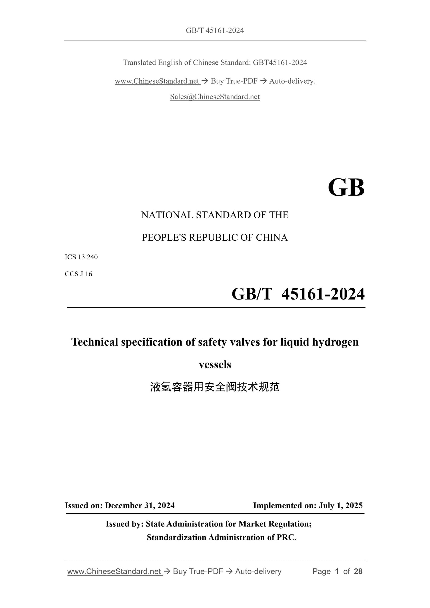
GB/T 45161-2024
GB
NATIONAL STANDARD OF THE
PEOPLE'S REPUBLIC OF CHINA
ICS 13.240
CCS J 16
Technical specification of safety valves for liquid hydrogen
vessels
ISSUED ON. DECEMBER 31, 2024
IMPLEMENTED ON. JULY 1, 2025
Issued by. State Administration for Market Regulation;
Standardization Administration of PRC.
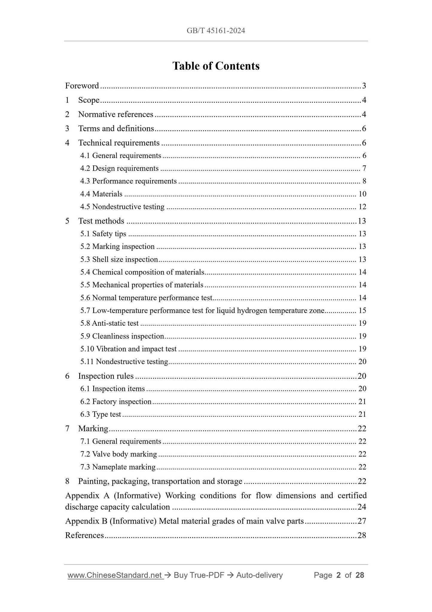
Table of Contents
Foreword... 3
1 Scope... 4
2 Normative references... 4
3 Terms and definitions... 6
4 Technical requirements... 6
4.1 General requirements... 6
4.2 Design requirements... 7
4.3 Performance requirements... 8
4.4 Materials... 10
4.5 Nondestructive testing... 12
5 Test methods... 13
5.1 Safety tips... 13
5.2 Marking inspection... 13
5.3 Shell size inspection... 13
5.4 Chemical composition of materials... 14
5.5 Mechanical properties of materials... 14
5.6 Normal temperature performance test... 14
5.7 Low-temperature performance test for liquid hydrogen temperature zone... 15
5.8 Anti-static test... 19
5.9 Cleanliness inspection... 19
5.10 Vibration and impact test... 19
5.11 Nondestructive testing... 20
6 Inspection rules... 20
6.1 Inspection items... 20
6.2 Factory inspection... 21
6.3 Type test... 21
7 Marking... 22
7.1 General requirements... 22
7.2 Valve body marking... 22
7.3 Nameplate marking... 22
8 Painting, packaging, transportation and storage... 22
Appendix A (Informative) Working conditions for flow dimensions and certified
discharge capacity calculation... 24
Appendix B (Informative) Metal material grades of main valve parts... 27
References... 28
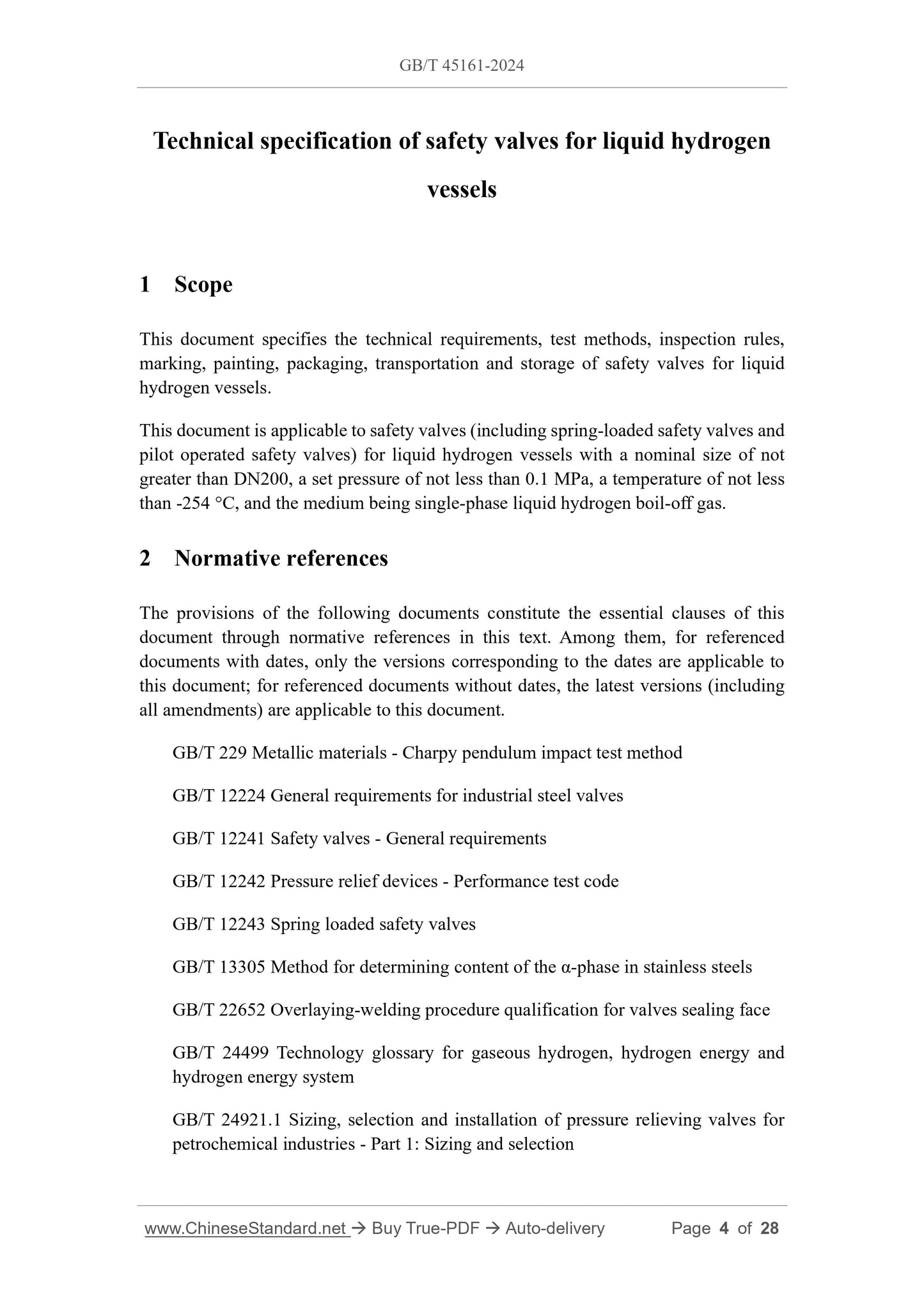
Technical specification of safety valves for liquid hydrogen
vessels
1 Scope
This document specifies the technical requirements, test methods, inspection rules,
marking, painting, packaging, transportation and storage of safety valves for liquid
hydrogen vessels.
This document is applicable to safety valves (including spring-loaded safety valves and
pilot operated safety valves) for liquid hydrogen vessels with a nominal size of not
greater than DN200, a set pressure of not less than 0.1 MPa, a temperature of not less
than -254 °C, and the medium being single-phase liquid hydrogen boil-off gas.
2 Normative references
The provisions of the following documents constitute the essential clauses of this
document through normative references in this text. Among them, for referenced
documents with dates, only the versions corresponding to the dates are applicable to
this document; for referenced documents without dates, the latest versions (including
all amendments) are applicable to this document.
GB/T 229 Metallic materials - Charpy pendulum impact test method
GB/T 12224 General requirements for industrial steel valves
GB/T 12241 Safety valves - General requirements
GB/T 12242 Pressure relief devices - Performance test code
GB/T 12243 Spring loaded safety valves
GB/T 13305 Method for determining content of the α-phase in stainless steels
GB/T 22652 Overlaying-welding procedure qualification for valves sealing face
GB/T 24499 Technology glossary for gaseous hydrogen, hydrogen energy and
hydrogen energy system
GB/T 24921.1 Sizing, selection and installation of pressure relieving valves for
petrochemical industries - Part 1.Sizing and selection
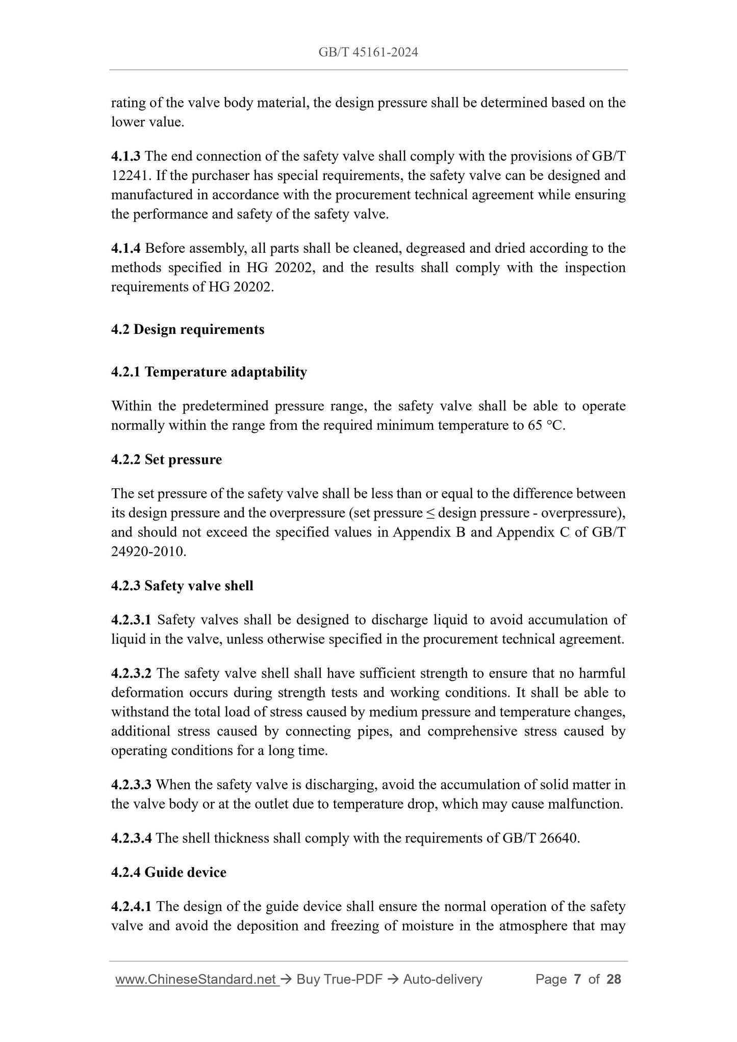
rating of the valve body material, the design pressure shall be determined based on the
lower value.
4.1.3 The end connection of the safety valve shall comply with the provisions of GB/T
12241.If the purchaser has special requirements, the safety valve can be designed and
manufactured in accordance with the procurement technical agreement while ensuring
the performance and safety of the safety valve.
4.1.4 Before assembly, all parts shall be cleaned, degreased and dried according to the
methods specified in HG 20202, and the results shall comply with the inspection
requirements of HG 20202.
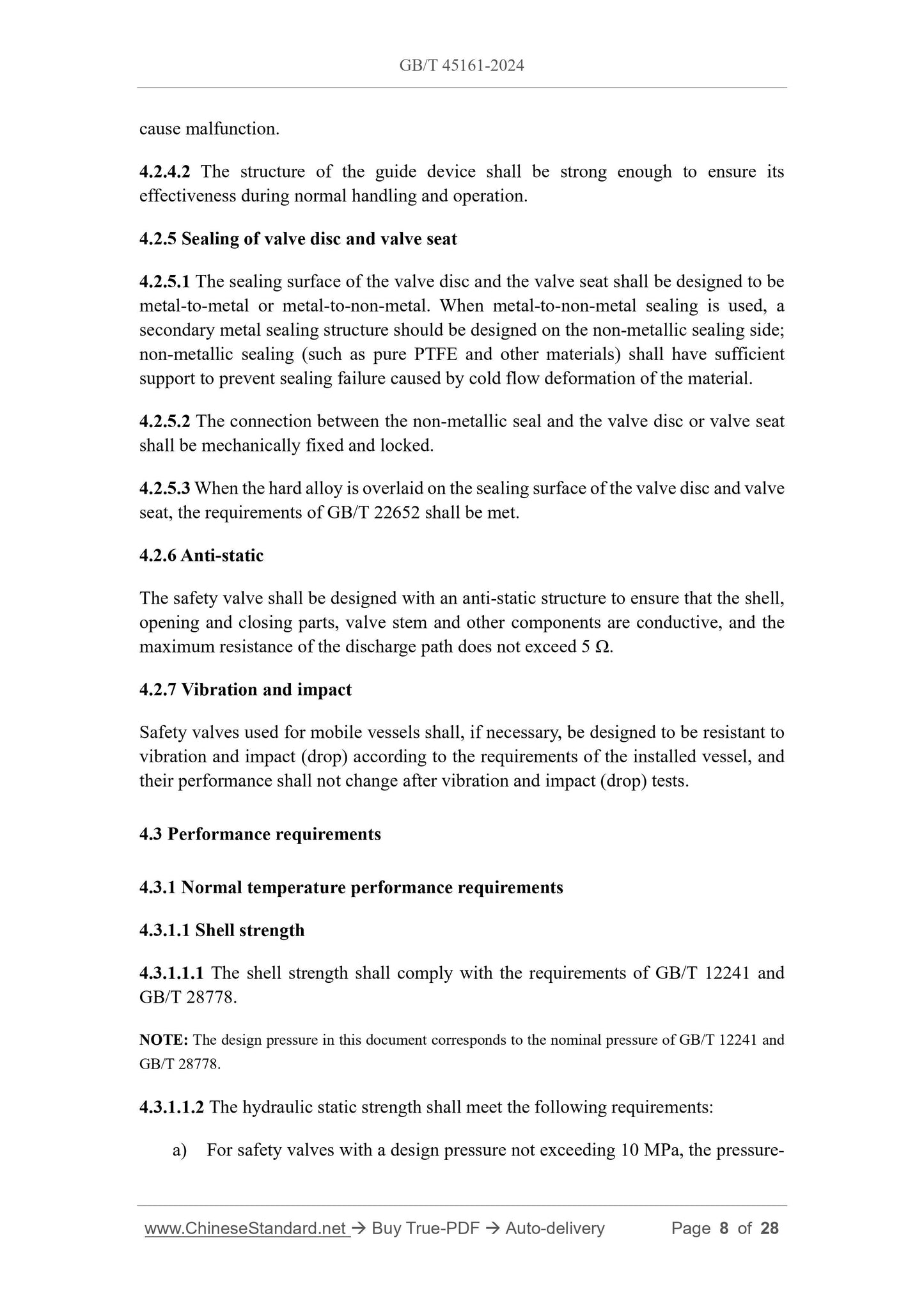
4.2 Design requirements
4.2.1 Temperature adaptability
Within the predetermined pressure range, the safety valve shall be able to operate
normally within the range from the required minimum temperature to 65 °C.
4.2.2 Set pressure
The set pressure of the safety valve shall be less than or equal to the difference between
its design pressure and the overpressure (set pressure ≤ design pressure - overpressure),
and should not exceed the specified values in Appendix B and Appendix C of GB/T
24920-2010.
4.2.3 Safety valve shell
4.2.3.1 Safety valves shall be designed to discharge liquid to avoid accumulation of
liquid in the valve, unless otherwise specified in the procurement technical agreement.
4.2.3.2 The safety valve shell shall have sufficient strength to ensure that no harmful
deformation occurs during strength tests and working conditions. It shall be able to
withstand the total load of stress caused by medium pressure and temperature changes,
additional stress caused by connecting pipes, and comprehensive stress caused by
operating conditions for a long time.
4.2.3.3 When the safety valve is discharging, avoid the accumulation of solid matter in
the valve body or at the outlet due to temperature drop, which may cause malfunction.
4.2.3.4 The shell thickness shall comply with the requirements of GB/T 26640.
4.2.4 Guide device
4.2.4.1 The design of the guide device shall ensure the normal operation of the safety
valve and avoid the deposition and freezing of moisture in the atmosphere that may
cause malfunction.
4.2.4.2 The structure of the guide device shall be strong enough to ensure its
effectiveness during normal handling and operation.
4.2.5 Sealing of valve disc and valve seat
4.2.5.1 The sealing surface of the valve disc and the valve seat shall be designed to be
metal-to-metal or metal-to-non-metal. When metal-to-non-metal sealing is used, a
secondary metal sealing structure should be designed on the non-metallic sealing side;
non-metallic sealing (such as pure PTFE and other materials) shall have sufficient
support to prevent sealing failure caused by cold flow deformation of the material.
4.2.5.2 The connection between the non-metallic seal and the valve disc or valve seat
shall be mechanically fixed and locked.
4.2.5.3 When the hard alloy is overlaid on the sealing surface of the valve disc and valve
seat, the requirements of GB/T 22652 shall be met.
4.2.6 Anti-static
The safety valve shall be designed with an anti-static structure to ensure that the shell,
opening and closing parts, valve stem and other components are conductive, and the
maximum resistance of the discharge path does not exceed 5 Ω.
4.2.7 Vibration and impact
Safety valves used for mobile vessels shall, if necessary, be designed to be resistant to
vibration and impact (drop) according to the requirements of the installed vessel, and
their performance shall not change after vibration and impact (drop) tests.
4.3 Performance requirements
4.3.1 Normal temperature performance requirements
4.3.1.1 Shell strength
4.3.1.1.1 The shell strength shall comply with the requirements of GB/T 12241 and
GB/T 28778.
NOTE. The design pressure in this document corresponds to the nominal pressure of GB/T 12241 and
GB/T 28778.
4.3.1.1.2 The hydraulic static strength shall meet the following requirements.
a) For safety valves with a design pressure not exceeding 10 MPa, the pressure-
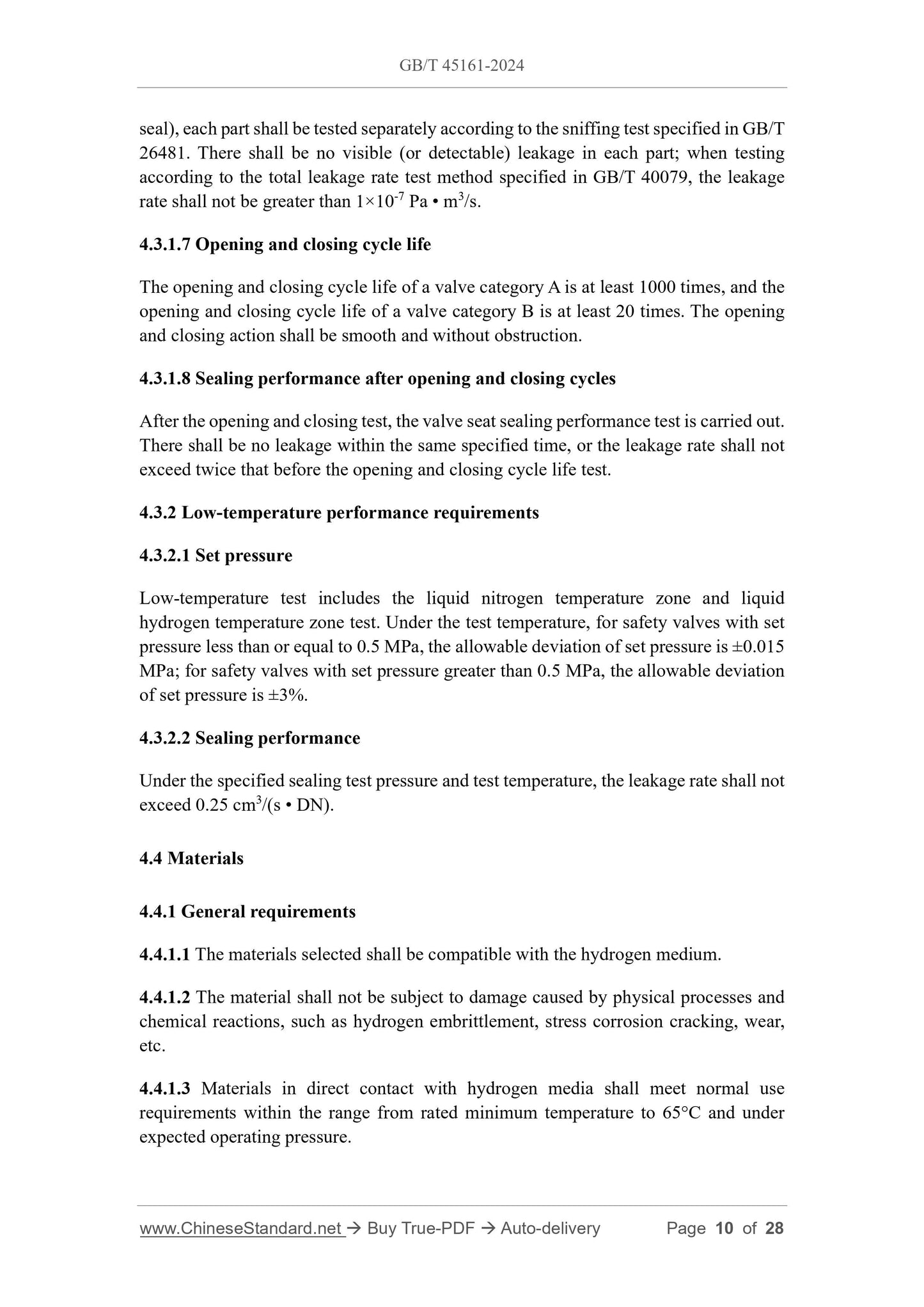
seal), each part shall be tested separately according to the sniffing test specified in GB/T
26481.There shall be no visible (or detectable) leakage in each part; when testing
according to the total leakage rate test method specified in GB/T 40079, the leakage
rate shall not be greater than 1×10⁻⁷ Pa • m3/s.
4.3.1.7 Opening and closing cycle life
The opening and closing cycle life of a valve category A is at least 1000 times, and the
opening and closing cycle life of a valve category B is at least 20 times. The opening
and closing action shall be smooth and without obstruction.
4.3.1.8 Sealing performance after opening and closing cycles
After the opening and closing test, the valve seat sealing performance test is carried out.
There shall be no leakage within the same specified time, or the leakage rate shall not
exceed twice that before the opening and closing cycle life test.
4.3.2 Low-temperature performance requirements
4.3.2.1 Set pressure
Low-temperature test includes the liquid nitrogen temperature zone and liquid
hydrogen temperature zone test. Under the test temperature, for safety valves with set
pressure less than or equal to 0.5 MPa, the allowable deviation of set pressure is ±0.015
MPa; for safety valves with set pressure greater than 0.5 MPa, the allowable deviation
of set pressure is ±3%.
4.3.2.2 Sealing performance
Under the specified sealing test pressure and test temperature, the leakage rate shall not
exceed 0.25 cm3/(s • DN).
4.4 Materials
4.4.1 General requirements
4.4.1.1 The materials selected shall be compatible with the hydrogen medium.
4.4.1.2 The material shall not be subject to damage caused by physical processes and
chemical reactions, such as hydrogen embrittlement, stress corrosion cracking, wear,
etc.
4.4.1.3 Materials in direct contact with hydrogen media shall meet normal use
requirements within the range from rated minimum temperature to 65°C and under
expected operating pressure.
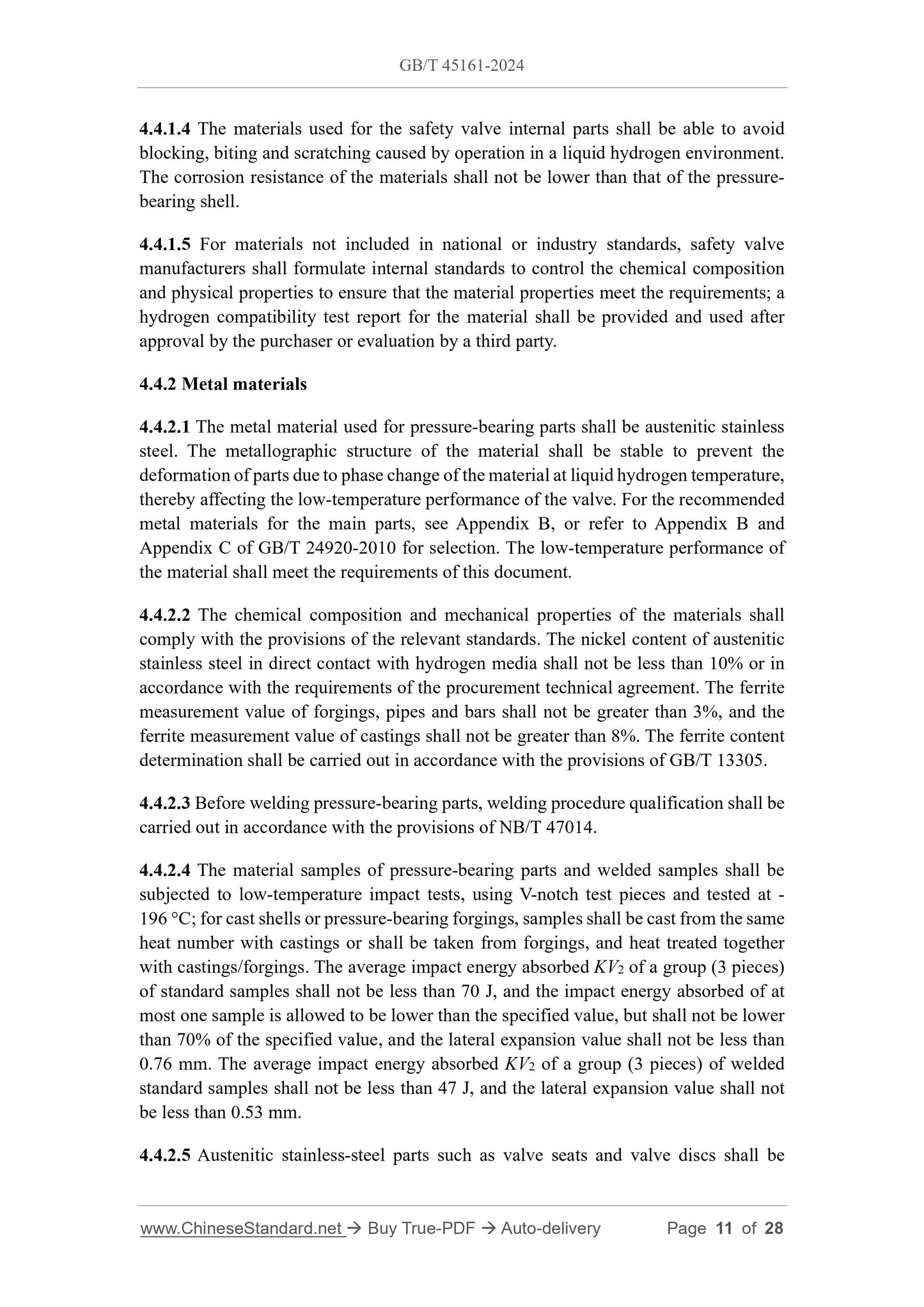
4.4.1.4 The materials used for the safety valve internal parts shall be able to avoid
blocking, biting and scratching caused by operation in a liquid hydrogen environment.
The corrosion resistance of the materials shall not be lower than that of the pressure-
bearing shell.
4.4.1.5 For materials not included in national or industry standards, safety valve
manufacturers shall formulate internal standards to control the chemical composition
and physical properties to ensure that the material properties meet the requirements; a
hydrogen compatibility test report for the material shall be provided and used after
approval by the purchaser or evaluation by a third party.
4.4.2 Metal materials
4.4.2.1 The metal material used for pressure-bearing parts shall be austenitic stainless
steel. The metallographic structure of the material shall be stable to prevent the
deformation of parts due to phase change of the material at liquid hydrogen temperature,
thereby affecting the low-temperature performance of the valve. For the recommended
metal materials for the main parts, see Appendix B, or refer to Appendix B and
Appendix C of GB/T 24920-2010 for selection. The low-temperature performance of
the material shall meet the requirements of this document.
4.4.2.2 The chemical composition and mechanical properties of the materials shall
comply with the provisions of the relevant standards. The nickel content of austenitic
stainless steel in direct contact with hydrogen media shall not be less than 10% or in
accordance with the requirements of the procurement technical agreement. The ferrite
measurement value of forgings, pipes and bars shall not be greater than 3%, and the
ferrite measurement value of castings shall not be greater than 8%. The ferrite content
determination shall be carried out in accordance with the provisions of GB/T 13305.
4.4.2.3 Before welding pressure-bearing parts, welding procedure qualification shall be
carried out in accordance with the provisions of NB/T 47014.
4.4.2.4 The material samples of pressure-bearing parts and welded samples shall be
subjected to low-temperature impact tests, using V-notch test pieces and tested at -
196 °C; for cast shells or pressure-bearing forgings, samples shall be cast from the same
heat number with castings or shall be taken from forgings, and heat treated together
with castings/forgings. The average impact energy absorbed KV2 of a group (3 pieces)
of standard samples shall not be less than 70 J, and the impact energy absorbed of at
most one sample is allowed to be lower than the specified value, but shall not be lower
than 70% of the specified value, and the lateral expansion value shall not be less than
0.76 mm. The average impact energy absorbed KV2 of a group (3 pieces) of welded
standard samples shall not be less than 47 J, and the lateral expansion value shall not
be less than 0.53 mm.
4.4.2.5 Austenitic stainless-steel parts such as valve seats and valve discs shall be
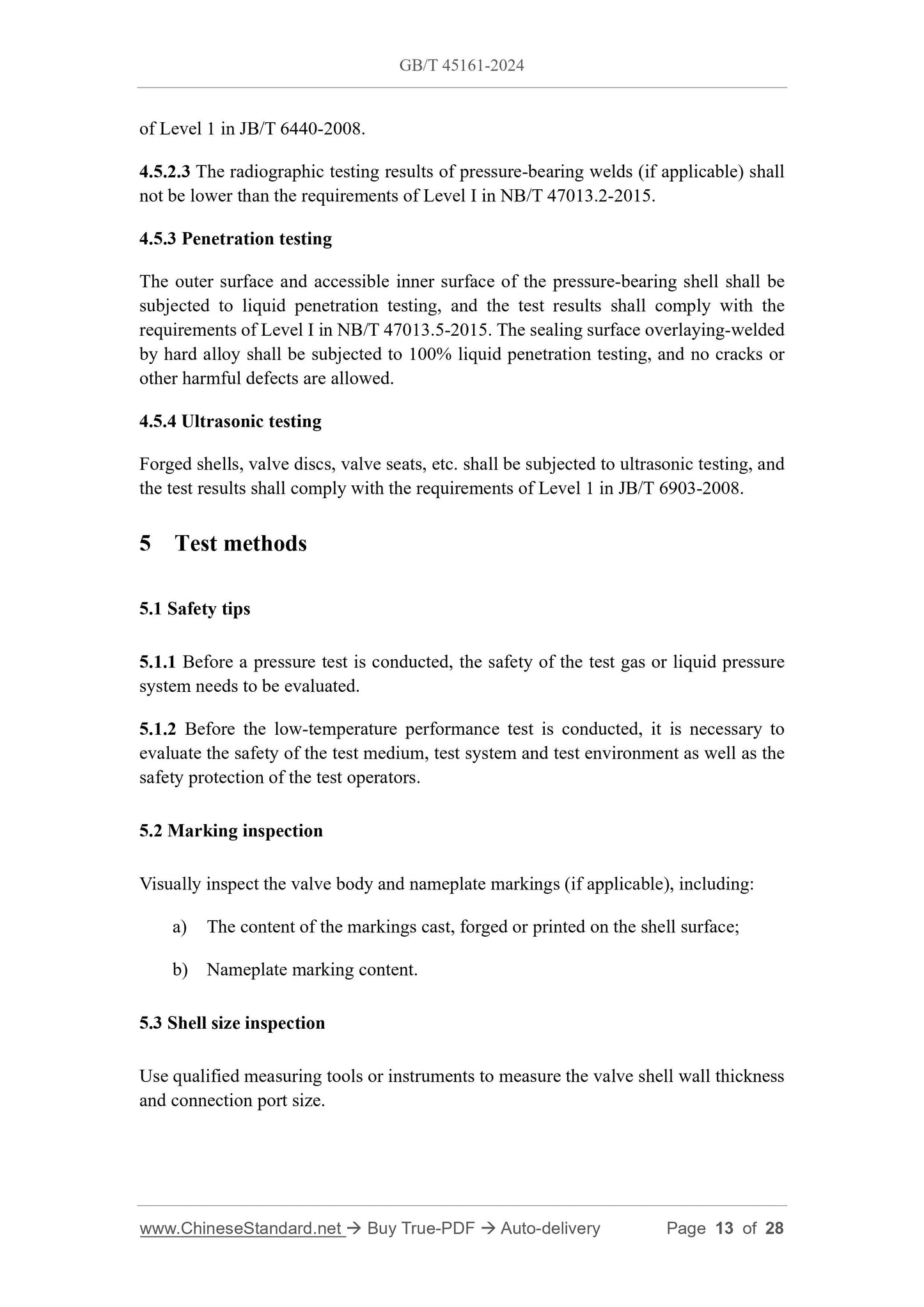
of Level 1 in JB/T 6440-2008.
4.5.2.3 The radiographic testing results of pressure-bearing welds (if applicable) shall
not be lower than the requirements of Level Ⅰ in NB/T 47013.2-2015.
4.5.3 Penetration testing
The outer surface and accessible inner surface of the pressure-bearing shell shall be
subjected to liquid penetration testing, and the test results shall comply with the
requirements of Level I in NB/T 47013.5-2015.The sealing surface overlaying-welded
by hard alloy shall be subjected to 100% liquid penetration testing, and no cracks or
other harmful defects are allowed.
4.5.4 Ultrasonic testing
Forged shells, valve discs, valve seats, etc. shall be subjected to ultrasonic testing, and
the test results shall comply with the requirements of Level 1 in JB/T 6903-2008.
5 Test methods
5.1 Safety tips
5.1.1 Before a pressure test is conducted, the safety of the test gas or liquid pressure
system needs to be evaluated.
5.1.2 Before the low-temperature performance test is conducted, it is necessary to
evaluate the safety of the test medium, test system and test environment as well as the
safety protection of the test operators.
5.2 Marking inspection
Visually inspect the valve body and nameplate markings (if applicable), including.
a) The content of the markings cast, forged or printed on the shell surface;
b) Nameplate marking content.
5.3 Shell size inspection
Use qualified measuring tools or instruments to measure the valve shell wall thickness
and connection port size.
5.4 Chemical composition of materials
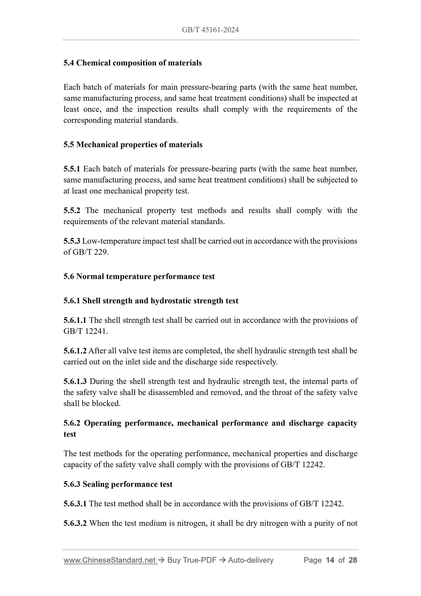
Each batch of materials for main pressure-bearing parts (with the same heat number,
same manufacturing process, and same heat treatment conditions) shall be inspected at
least once, and the ins...
View full details