1
/
of
12
www.ChineseStandard.us -- Field Test Asia Pte. Ltd.
GB/T 45092-2024 English PDF (GB/T45092-2024)
Regular price
$350.00
Regular price
Sale price
$350.00
Unit price
/
per
Shipping calculated at checkout.
Couldn't load pickup availability
GB/T 45092-2024: Testing and evaluation of electrodes performance for hydrogen production by water electrolysis
Delivery: 9 seconds. Download (and Email) true-PDF + Invoice.
Get Quotation: Click GB/T 45092-2024 (Self-service in 1-minute)
Historical versions (Master-website): GB/T 45092-2024
Preview True-PDF (Reload/Scroll-down if blank)
GB/T 45092-2024
GB
NATIONAL STANDARD OF THE
PEOPLE’S REPUBLIC OF CHINA
ICS 27.010
CCS F 19
Testing and evaluation of electrodes performance for
hydrogen production by water electrolysis
ISSUED ON: NOVEMBER 28, 2024
IMPLEMENTED ON: MARCH 01, 2025
Issued by: State Administration for Market Regulation;
National Standardization Administration.
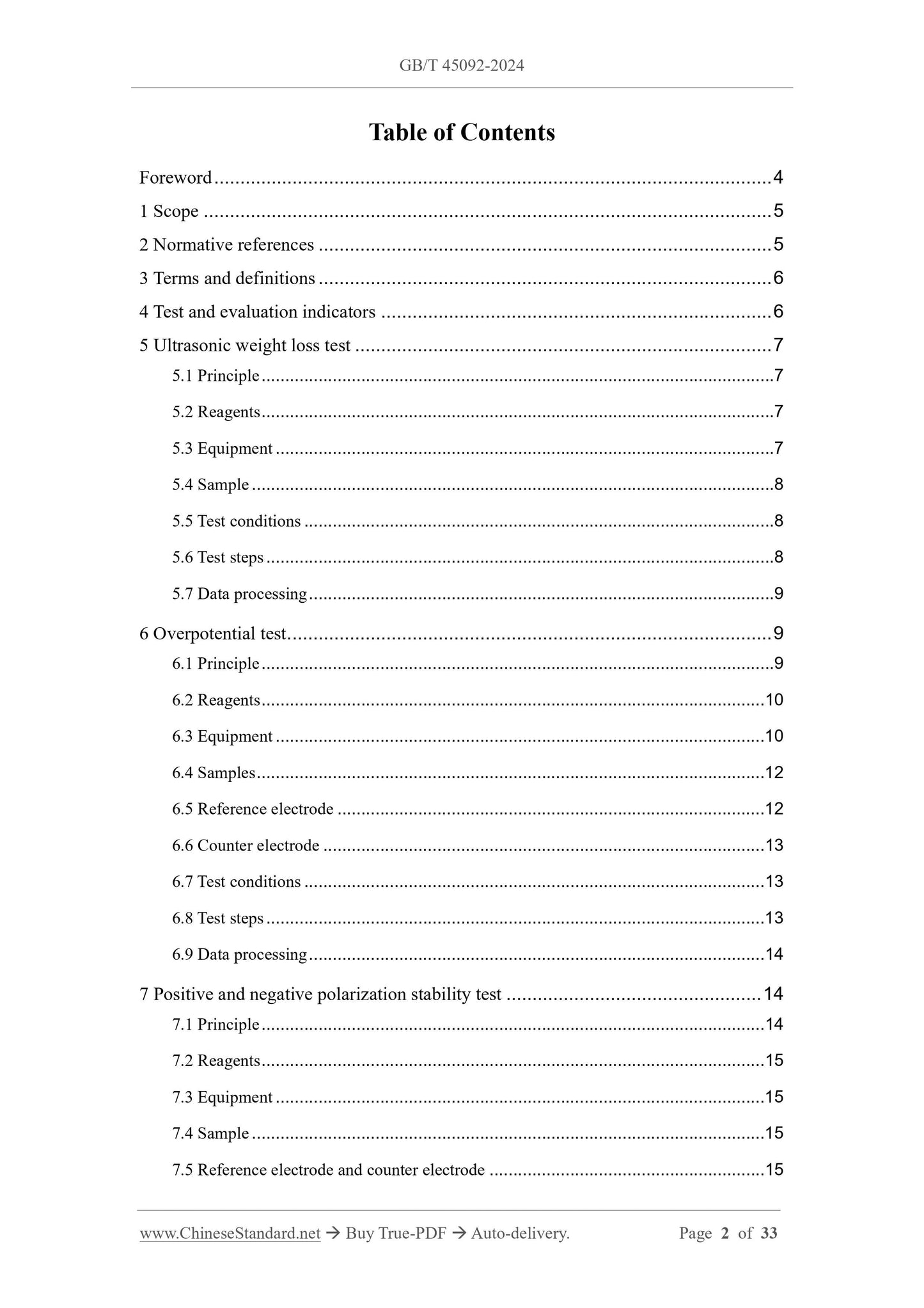
Table of Contents
Foreword ... 4
1 Scope ... 5
2 Normative references ... 5
3 Terms and definitions ... 6
4 Test and evaluation indicators ... 6
5 Ultrasonic weight loss test ... 7
5.1 Principle ... 7
5.2 Reagents ... 7
5.3 Equipment ... 7
5.4 Sample ... 8
5.5 Test conditions ... 8
5.6 Test steps ... 8
5.7 Data processing ... 9
6 Overpotential test ... 9
6.1 Principle ... 9
6.2 Reagents ... 10
6.3 Equipment ... 10
6.4 Samples ... 12
6.5 Reference electrode ... 12
6.6 Counter electrode ... 13
6.7 Test conditions ... 13
6.8 Test steps ... 13
6.9 Data processing ... 14
7 Positive and negative polarization stability test ... 14
7.1 Principle ... 14
7.2 Reagents ... 15
7.3 Equipment ... 15
7.4 Sample ... 15
7.5 Reference electrode and counter electrode ... 15
7.6 Test conditions ... 15
7.7 Test steps ... 15
7.8 Data processing ... 16
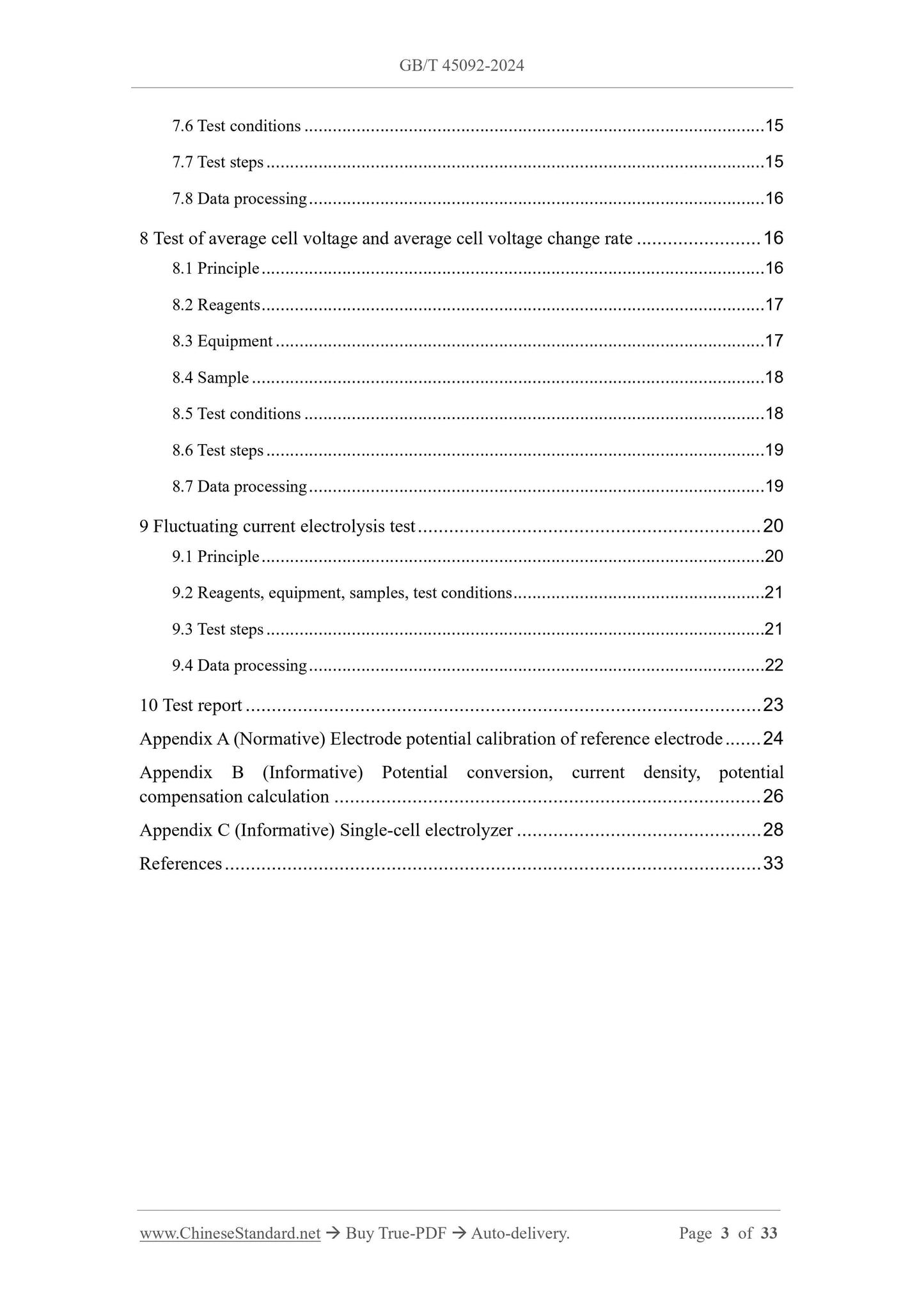
8 Test of average cell voltage and average cell voltage change rate ... 16
8.1 Principle ... 16
8.2 Reagents ... 17
8.3 Equipment ... 17
8.4 Sample ... 18
8.5 Test conditions ... 18
8.6 Test steps ... 19
8.7 Data processing ... 19
9 Fluctuating current electrolysis test ... 20
9.1 Principle ... 20
9.2 Reagents, equipment, samples, test conditions ... 21
9.3 Test steps ... 21
9.4 Data processing ... 22
10 Test report ... 23
Appendix A (Normative) Electrode potential calibration of reference electrode ... 24
Appendix B (Informative) Potential conversion, current density, potential
compensation calculation ... 26
Appendix C (Informative) Single-cell electrolyzer ... 28
References ... 33
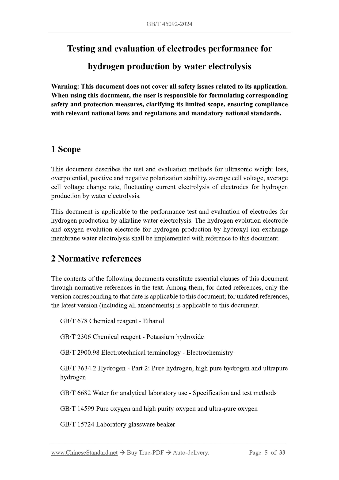
Testing and evaluation of electrodes performance for
hydrogen production by water electrolysis
Warning: This document does not cover all safety issues related to its application.
When using this document, the user is responsible for formulating corresponding
safety and protection measures, clarifying its limited scope, ensuring compliance
with relevant national laws and regulations and mandatory national standards.
1 Scope
This document describes the test and evaluation methods for ultrasonic weight loss,
overpotential, positive and negative polarization stability, average cell voltage, average
cell voltage change rate, fluctuating current electrolysis of electrodes for hydrogen
production by water electrolysis.
This document is applicable to the performance test and evaluation of electrodes for
hydrogen production by alkaline water electrolysis. The hydrogen evolution electrode
and oxygen evolution electrode for hydrogen production by hydroxyl ion exchange
membrane water electrolysis shall be implemented with reference to this document.
2 Normative references
The contents of the following documents constitute essential clauses of this document
through normative references in the text. Among them, for dated references, only the
version corresponding to that date is applicable to this document; for undated references,
the latest version (including all amendments) is applicable to this document.
GB/T 678 Chemical reagent - Ethanol
GB/T 2306 Chemical reagent - Potassium hydroxide
GB/T 2900.98 Electrotechnical terminology - Electrochemistry
GB/T 3634.2 Hydrogen - Part 2: Pure hydrogen, high pure hydrogen and ultrapure
hydrogen
GB/T 6682 Water for analytical laboratory use - Specification and test methods
GB/T 14599 Pure oxygen and high purity oxygen and ultra-pure oxygen
GB/T 15724 Laboratory glassware beaker
GB/T 21648 Industrial dense woven wire cloth
GB/T 28817 Single cell test methods for polymer electrolyte fuel cell (PEFC)
3 Terms and definitions
The terms and definitions defined in GB/T 2900.98, as well as the following terms and
definitions, apply to this document.
3.1
Overpotential
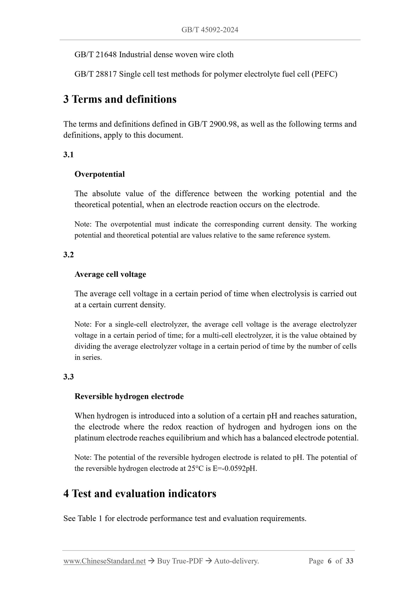
The absolute value of the difference between the working potential and the
theoretical potential, when an electrode reaction occurs on the electrode.
Note: The overpotential must indicate the corresponding current density. The working
potential and theoretical potential are values relative to the same reference system.
3.2
Average cell voltage
The average cell voltage in a certain period of time when electrolysis is carried out
at a certain current density.
Note: For a single-cell electrolyzer, the average cell voltage is the average electrolyzer
voltage in a certain period of time; for a multi-cell electrolyzer, it is the value obtained by
dividing the average electrolyzer voltage in a certain period of time by the number of cells
in series.
3.3
Reversible hydrogen electrode
When hydrogen is introduced into a solution of a certain pH and reaches saturation,
the electrode where the redox reaction of hydrogen and hydrogen ions on the
platinum electrode reaches equilibrium and which has a balanced electrode potential.
Note: The potential of the reversible hydrogen electrode is related to pH. The potential of
the reversible hydrogen electrode at 25°C is E=-0.0592pH.
4 Test and evaluation indicators
See Table 1 for electrode performance test and evaluation requirements.
5.4 Sample
5.4.1 Specifications
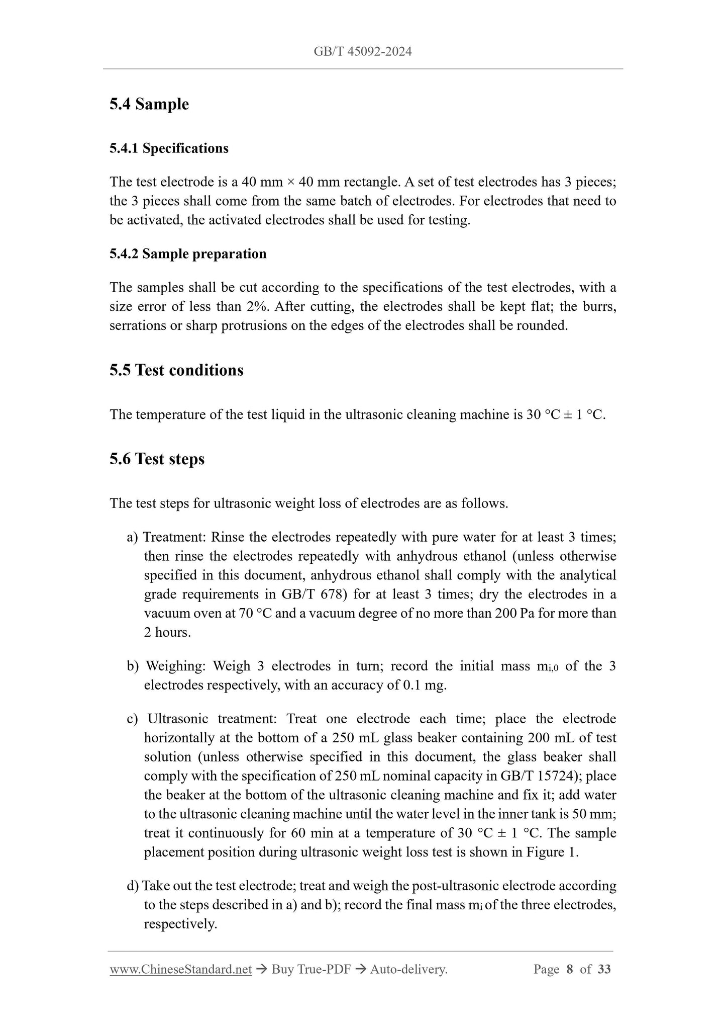
The test electrode is a 40 mm × 40 mm rectangle. A set of test electrodes has 3 pieces;
the 3 pieces shall come from the same batch of electrodes. For electrodes that need to
be activated, the activated electrodes shall be used for testing.
5.4.2 Sample preparation
The samples shall be cut according to the specifications of the test electrodes, with a
size error of less than 2%. After cutting, the electrodes shall be kept flat; the burrs,
serrations or sharp protrusions on the edges of the electrodes shall be rounded.
5.5 Test conditions
The temperature of the test liquid in the ultrasonic cleaning machine is 30 °C ± 1 °C.
5.6 Test steps
The test steps for ultrasonic weight loss of electrodes are as follows.
a) Treatment: Rinse the electrodes repeatedly with pure water for at least 3 times;
then rinse the electrodes repeatedly with anhydrous ethanol (unless otherwise
specified in this document, anhydrous ethanol shall comply with the analytical
grade requirements in GB/T 678) for at least 3 times; dry the electrodes in a
vacuum oven at 70 °C and a vacuum degree of no more than 200 Pa for more than
2 hours.
b) Weighing: Weigh 3 electrodes in turn; record the initial mass mi,0 of the 3
electrodes respectively, with an accuracy of 0.1 mg.
c) Ultrasonic treatment: Treat one electrode each time; place the electrode
horizontally at the bottom of a 250 mL glass beaker containing 200 mL of test
solution (unless otherwise specified in this document, the glass beaker shall
comply with the specification of 250 mL nominal capacity in GB/T 15724); place
the beaker at the bottom of the ultrasonic cleaning machine and fix it; add water
to the ultrasonic cleaning machine until the water level in the inner tank is 50 mm;
treat it continuously for 60 min at a temperature of 30 °C ± 1 °C. The sample
placement position during ultrasonic weight loss test is shown in Figure 1.
d) Take out the test electrode; treat and weigh the post-ultrasonic electrode according
to the steps described in a) and b); record the final mass mi of the three electrodes,
respectively.
electrode with an external salt bridge. Before use, the reference electrode shall be
calibrated for potential according to the method described in Appendix A.
6.6 Counter electrode
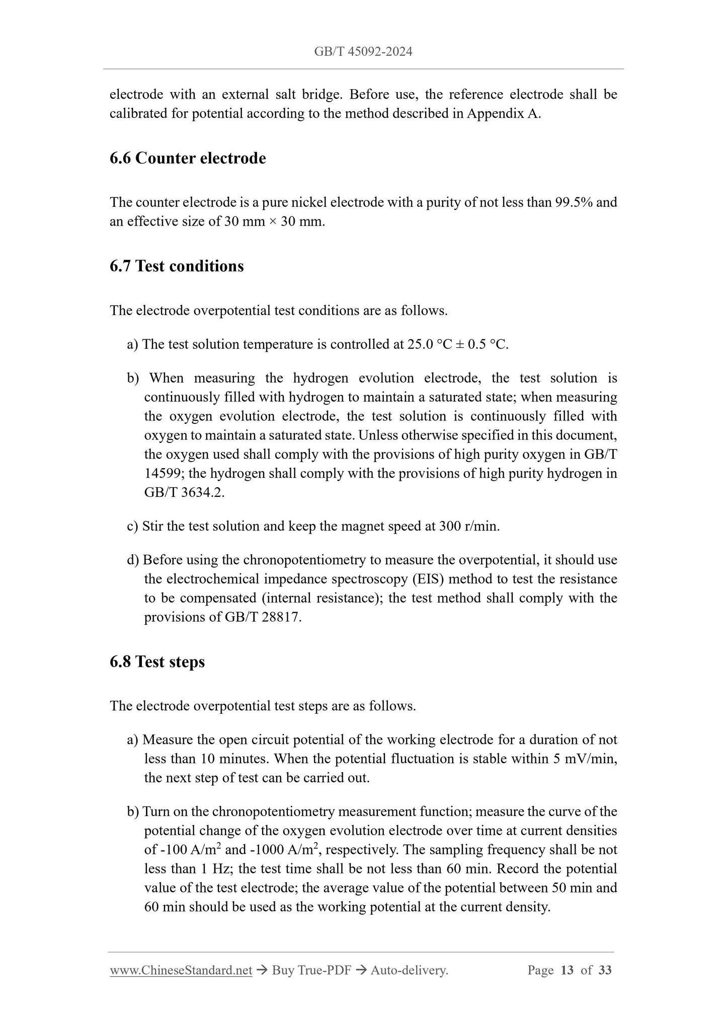
The counter electrode is a pure nickel electrode with a purity of not less than 99.5% and
an effective size of 30 mm × 30 mm.
6.7 Test conditions
The electrode overpotential test conditions are as follows.
a) The test solution temperature is controlled at 25.0 °C ± 0.5 °C.
b) When measuring the hydrogen evolution electrode, the test solution is
continuously filled with hydrogen to maintain a saturated state; when measuring
the oxygen evolution electrode, the test solution is continuously filled with
oxygen to maintain a saturated state. Unless otherwise specified in this document,
the oxygen used shall comply with the provisions of high purity oxygen in GB/T
14599; the hydrogen shall comply with the provisions of high purity hydrogen in
GB/T 3634.2.
c) Stir the test solution and keep the magnet speed at 300 r/min.
d) Before using the chronopotentiometry to measure the overpotential, it should use
the electrochemical impedance spectroscopy (EIS) method to test the resistance
to be compensated (internal resistance); the test method shall comply with the
provisions of GB/T 28817.
6.8 Test steps
The electrode overpotential test steps are as follows.
a) Measure the open circuit potential of the working electrode for a duration of not
less than 10 minutes. When the potential fluctuation is stable within 5 mV/min,
the next step of test can be carried out.
b) Turn on the chronopotentiometry measurement function; measure the curve of the
potential change of the oxygen evolution electrode over time at current densities
of -100 A/m2 and -1000 A/m2, respectively. The sampling frequency shall be not
less than 1 Hz; the test time shall be not less than 60 min. Record the potential
value of the test electrode; the average value of the potential between 50 min and
60 min should be used as the working potential at the current density.
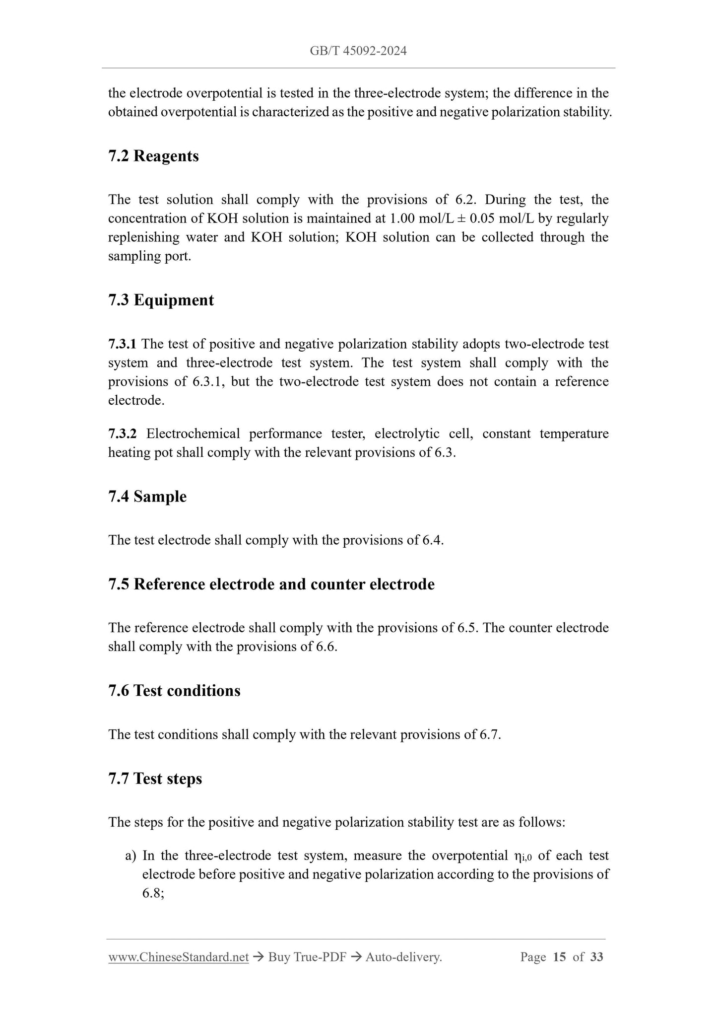
the electrode overpotential is tested in the three-electrode system; the difference in the
obtained overpotential is characterized as the positive and negative polarization stability.
7.2 Reagents
The test solution shall comply with the provisions of 6.2. During the test, the
concentration of KOH solution is maintained at 1.00 mol/L ± 0.05 mol/L by regularly
replenishing water and KOH solution; KOH solution can be collected through the
sampling port.
7.3 Equipment
7.3.1 The test of positive and negative polarization stability adopts two-electrode test
system and three-electrode test system. The test system shall comply with the
provisions of 6.3.1, but the two-electrode test system does not contain a reference
electrode.
7.3.2 Electrochemical performance tester, electrolytic cell, constant temperature
heating pot shall comply with the relevant provisions of 6.3.
7.4 Sample
The test electrode shall comply with the provisions of 6.4.
7.5 Reference electrode and counter electrode
The reference electrode shall comply with the provisions of 6.5. The counter electrode
shall comply with the provisions of 6.6.
7.6 Test conditions
The test conditions shall comply with the relevant provisions of 6.7.
7.7 Test steps
The steps for the positive and negative polarization stability test are as follows:
a) In the three-electrode test system, measure the overpotential ηi,0 of each test
electrode before positive and negative polarization according to the provisions of
6.8;
Note: The single-cell electrolyzer is a normal pressure electrolyzer.
8.3.4 Alkali circulation pump
The flow rate of the alkali circulation pump should be 0.5 L/min.
8.3.5 Rehydration pump
The flow rate of the rehydration pump is not less than 20 mL/h.
8.3.6 Gas-liquid separator
The material of the gas-liquid separator is polypropylene, polytetrafluoroethylene,
carbon steel nickel-plated or 316 L stainless steel.
8.4 Sample
The test electrode shall meet the following requirements:
a) The electrode shape is rectangular, the size is 50 mm × 40 mm, the length and
width size errors are ≤ ±1 mm; the actual size of the electrode is measured with a
vernier caliper;
b) When the test electrode is a single hydrogen evolution electrode or a single oxygen
evolution electrode, a non-coated nickel mesh, which has a basic mesh number
(British system) of 46 and a wire diameter of 0.25 mm, is used as the
corresponding oxygen evolution anode or hydrogen evolution electrode. The
nickel mesh shall comply with the provisions of GB/T 21648;
c) After cutting, the test electrode shall be kept flat; the burrs, serrations or sharp
protrusions on the electrode edges shall be rounded;
d) For electrodes that need to be activated, the activated electrodes shall be used;
e) The number of test samples should be no less than 3 pieces.
8.5 Test conditions
The test of the average voltage of the cell shall meet the following conditions:
a) The test solution temperature is 85 °C ± 1 °C;
b) Adjust the cathode and anode outlet valves to maintain the dynamic balance of
the two-electrode gas pressure;
c) During the test, water shall be added to ensure that the density of the test solution
is 1.28 g/cm3 ± 0.03 g/cm3.
Note: The density is the corresponding value at 25 °C.
8.6 Test steps
The test steps for the average cell voltage and the average cell voltage change rate are
as follows.
a) Before the test electrode is installed in the electrolytic cell, the test electrode shall
be cleaned according to the provisions of 5.6 a); after treatment, the mass of the
electrode is weighed as mi,0, with an accuracy of 0.1 mg.
b) Start preheating: 10 min before the test, turn on the constant current power supply
for preheating.
c) In the single-cell electrolytic cell test system, start the constant current electrolysis
test, so that the electrolytic cell continues to operate at a constant current density
for at least 500 h; the sampling interval shall be 30 s.
Note: The current density is usually set to 3000 A/m2, 4000 A/m2, 5000 A/m2,
8000 A/m2 or 10000 A/m2. The set test current density value shall be noted in the
report.
d) During the test time, record the cell voltage at 70 h ~ 72 h and at (t + 70 h) ~ (t +
72 h), where t ≥ 500 h. The algebraic mean of the cell voltage during the above
two periods is taken as the cell...
Share