1
/
of
12
www.ChineseStandard.us -- Field Test Asia Pte. Ltd.
GB/T 45027-2024 English PDF (GB/T45027-2024)
Regular price
$665.00
Regular price
Sale price
$665.00
Unit price
/
per
Shipping calculated at checkout.
Couldn't load pickup availability
GB/T 45027-2024: Valves for liquid hydrogen - General specification
Delivery: 9 seconds. Download (and Email) true-PDF + Invoice.
Get Quotation: Click GB/T 45027-2024 (Self-service in 1-minute)
Newer / historical versions: GB/T 45027-2024
Preview True-PDF (Reload/Scroll-down if blank)
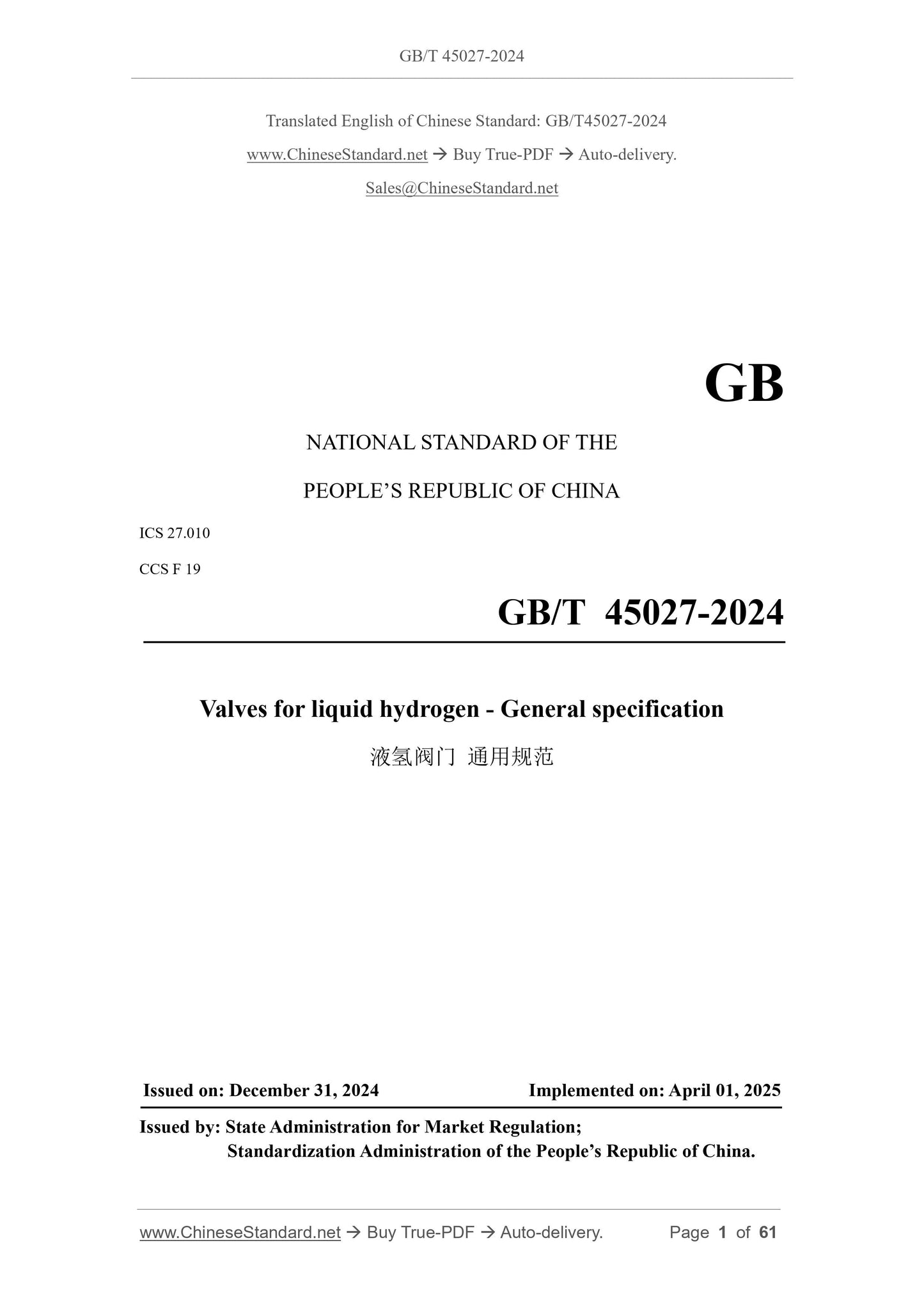
GB/T 45027-2024
GB
NATIONAL STANDARD OF THE
PEOPLE’S REPUBLIC OF CHINA
ICS 27.010
CCS F 19
Valves for liquid hydrogen - General specification
ISSUED ON. DECEMBER 31, 2024
IMPLEMENTED ON. APRIL 01, 2025
Issued by. State Administration for Market Regulation;
Standardization Administration of the People’s Republic of China.
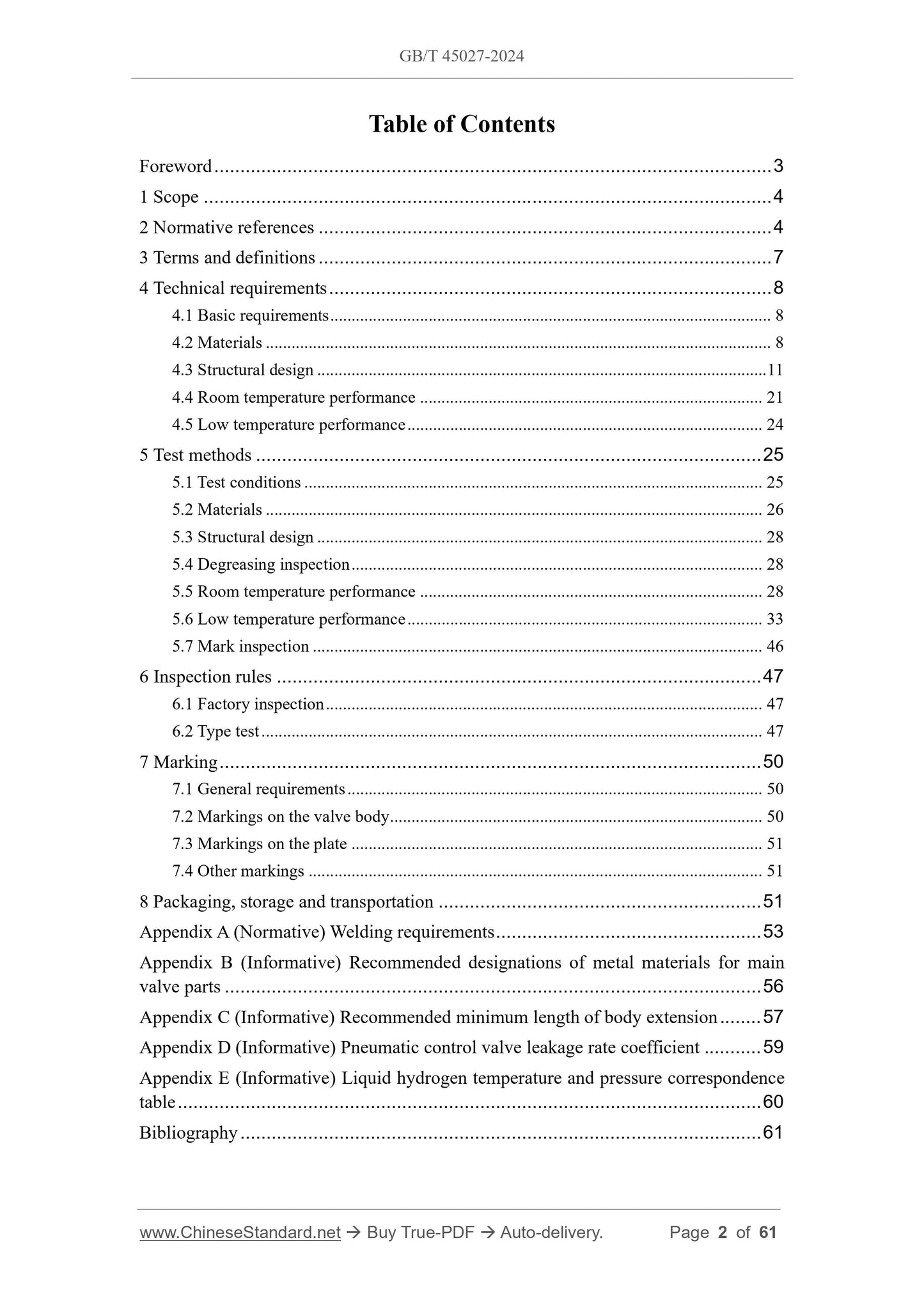
Table of Contents
Foreword... 3
1 Scope... 4
2 Normative references... 4
3 Terms and definitions... 7
4 Technical requirements... 8
4.1 Basic requirements... 8
4.2 Materials... 8
4.3 Structural design... 11
4.4 Room temperature performance... 21
4.5 Low temperature performance... 24
5 Test methods... 25
5.1 Test conditions... 25
5.2 Materials... 26
5.3 Structural design... 28
5.4 Degreasing inspection... 28
5.5 Room temperature performance... 28
5.6 Low temperature performance... 33
5.7 Mark inspection... 46
6 Inspection rules... 47
6.1 Factory inspection... 47
6.2 Type test... 47
7 Marking... 50
7.1 General requirements... 50
7.2 Markings on the valve body... 50
7.3 Markings on the plate... 51
7.4 Other markings... 51
8 Packaging, storage and transportation... 51
Appendix A (Normative) Welding requirements... 53
Appendix B (Informative) Recommended designations of metal materials for main
valve parts... 56
Appendix C (Informative) Recommended minimum length of body extension... 57
Appendix D (Informative) Pneumatic control valve leakage rate coefficient... 59
Appendix E (Informative) Liquid hydrogen temperature and pressure correspondence
table... 60
Bibliography... 61
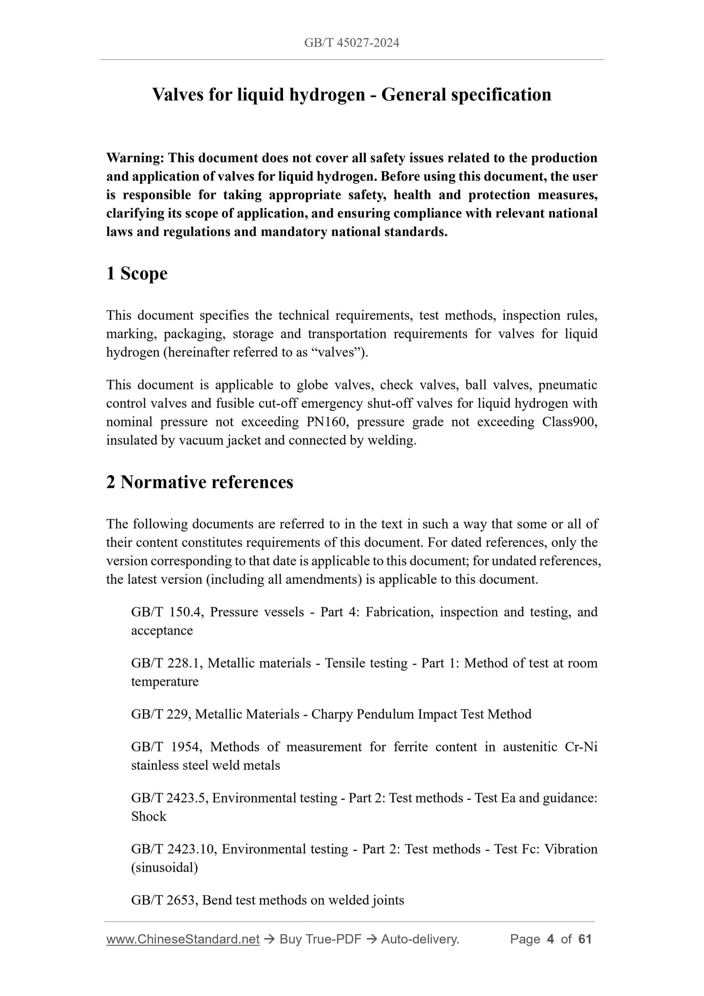
Valves for liquid hydrogen - General specification
Warning. This document does not cover all safety issues related to the production
and application of valves for liquid hydrogen. Before using this document, the user
is responsible for taking appropriate safety, health and protection measures,
clarifying its scope of application, and ensuring compliance with relevant national
laws and regulations and mandatory national standards.
1 Scope
This document specifies the technical requirements, test methods, inspection rules,
marking, packaging, storage and transportation requirements for valves for liquid
hydrogen (hereinafter referred to as “valves”).
This document is applicable to globe valves, check valves, ball valves, pneumatic
control valves and fusible cut-off emergency shut-off valves for liquid hydrogen with
nominal pressure not exceeding PN160, pressure grade not exceeding Class900,
insulated by vacuum jacket and connected by welding.
2 Normative references
The following documents are referred to in the text in such a way that some or all of
their content constitutes requirements of this document. For dated references, only the
version corresponding to that date is applicable to this document; for undated references,
the latest version (including all amendments) is applicable to this document.
GB/T 150.4, Pressure vessels - Part 4.Fabrication, inspection and testing, and
acceptance
GB/T 228.1, Metallic materials - Tensile testing - Part 1.Method of test at room
temperature
GB/T 229, Metallic Materials - Charpy Pendulum Impact Test Method
GB/T 1954, Methods of measurement for ferrite content in austenitic Cr-Ni
stainless steel weld metals
GB/T 2423.5, Environmental testing - Part 2.Test methods - Test Ea and guidance.
Shock
GB/T 2423.10, Environmental testing - Part 2.Test methods - Test Fc. Vibration
(sinusoidal)
GB/T 2653, Bend test methods on welded joints
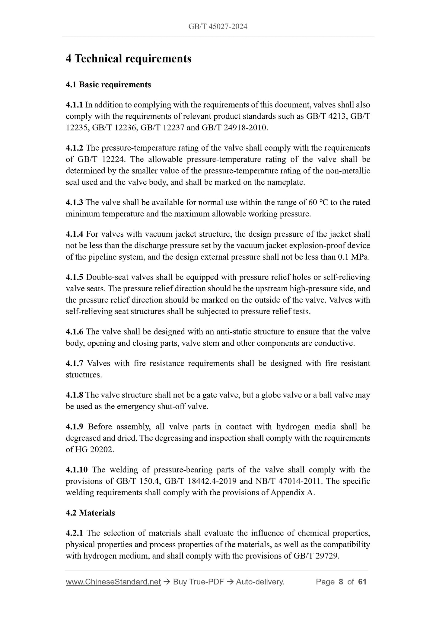
4 Technical requirements
4.1 Basic requirements
4.1.1 In addition to complying with the requirements of this document, valves shall also
comply with the requirements of relevant product standards such as GB/T 4213, GB/T
12235, GB/T 12236, GB/T 12237 and GB/T 24918-2010.
4.1.2 The pressure-temperature rating of the valve shall comply with the requirements
of GB/T 12224.The allowable pressure-temperature rating of the valve shall be
determined by the smaller value of the pressure-temperature rating of the non-metallic
seal used and the valve body, and shall be marked on the nameplate.
4.1.3 The valve shall be available for normal use within the range of 60 ℃ to the rated
minimum temperature and the maximum allowable working pressure.
4.1.4 For valves with vacuum jacket structure, the design pressure of the jacket shall
not be less than the discharge pressure set by the vacuum jacket explosion-proof device
of the pipeline system, and the design external pressure shall not be less than 0.1 MPa.
4.1.5 Double-seat valves shall be equipped with pressure relief holes or self-relieving
valve seats. The pressure relief direction should be the upstream high-pressure side, and
the pressure relief direction should be marked on the outside of the valve. Valves with
self-relieving seat structures shall be subjected to pressure relief tests.
4.1.6 The valve shall be designed with an anti-static structure to ensure that the valve
body, opening and closing parts, valve stem and other components are conductive.
4.1.7 Valves with fire resistance requirements shall be designed with fire resistant
structures.
4.1.8 The valve structure shall not be a gate valve, but a globe valve or a ball valve may
be used as the emergency shut-off valve.
4.1.9 Before assembly, all valve parts in contact with hydrogen media shall be
degreased and dried. The degreasing and inspection shall comply with the requirements
of HG 20202.
4.1.10 The welding of pressure-bearing parts of the valve shall comply with the
provisions of GB/T 150.4, GB/T 18442.4-2019 and NB/T 47014-2011.The specific
welding requirements shall comply with the provisions of Appendix A.
4.2 Materials
4.2.1 The selection of materials shall evaluate the influence of chemical properties,
physical properties and process properties of the materials, as well as the compatibility
with hydrogen medium, and shall comply with the provisions of GB/T 29729.
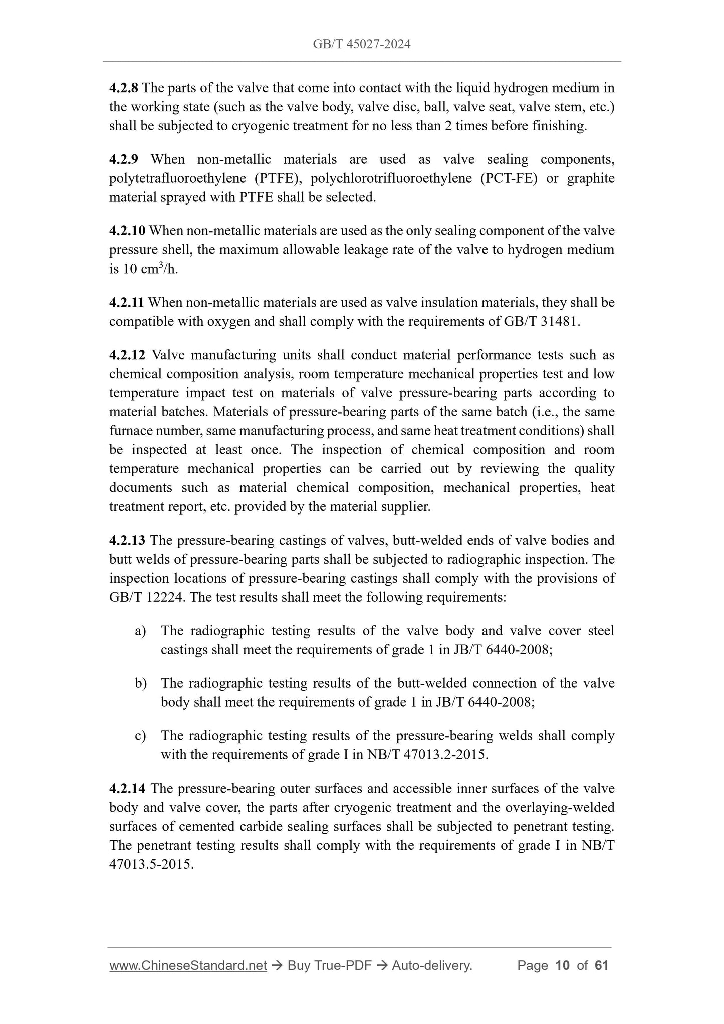
4.2.8 The parts of the valve that come into contact with the liquid hydrogen medium in
the working state (such as the valve body, valve disc, ball, valve seat, valve stem, etc.)
shall be subjected to cryogenic treatment for no less than 2 times before finishing.
4.2.9 When non-metallic materials are used as valve sealing components,
polytetrafluoroethylene (PTFE), polychlorotrifluoroethylene (PCT-FE) or graphite
material sprayed with PTFE shall be selected.
4.2.10 When non-metallic materials are used as the only sealing component of the valve
pressure shell, the maximum allowable leakage rate of the valve to hydrogen medium
is 10 cm3/h.
4.2.11 When non-metallic materials are used as valve insulation materials, they shall be
compatible with oxygen and shall comply with the requirements of GB/T 31481.
4.2.12 Valve manufacturing units shall conduct material performance tests such as
chemical composition analysis, room temperature mechanical properties test and low
temperature impact test on materials of valve pressure-bearing parts according to
material batches. Materials of pressure-bearing parts of the same batch (i.e., the same
furnace number, same manufacturing process, and same heat treatment conditions) shall
be inspected at least once. The inspection of chemical composition and room
temperature mechanical properties can be carried out by reviewing the quality
documents such as material chemical composition, mechanical properties, heat
treatment report, etc. provided by the material supplier.
4.2.13 The pressure-bearing castings of valves, butt-welded ends of valve bodies and
butt welds of pressure-bearing parts shall be subjected to radiographic inspection. The
inspection locations of pressure-bearing castings shall comply with the provisions of
GB/T 12224.The test results shall meet the following requirements.
a) The radiographic testing results of the valve body and valve cover steel
castings shall meet the requirements of grade 1 in JB/T 6440-2008;
b) The radiographic testing results of the butt-welded connection of the valve
body shall meet the requirements of grade 1 in JB/T 6440-2008;
c) The radiographic testing results of the pressure-bearing welds shall comply
with the requirements of grade I in NB/T 47013.2-2015.
4.2.14 The pressure-bearing outer surfaces and accessible inner surfaces of the valve
body and valve cover, the parts after cryogenic treatment and the overlaying-welded
surfaces of cemented carbide sealing surfaces shall be subjected to penetrant testing.
The penetrant testing results shall comply with the requirements of grade I in NB/T
47013.5-2015.
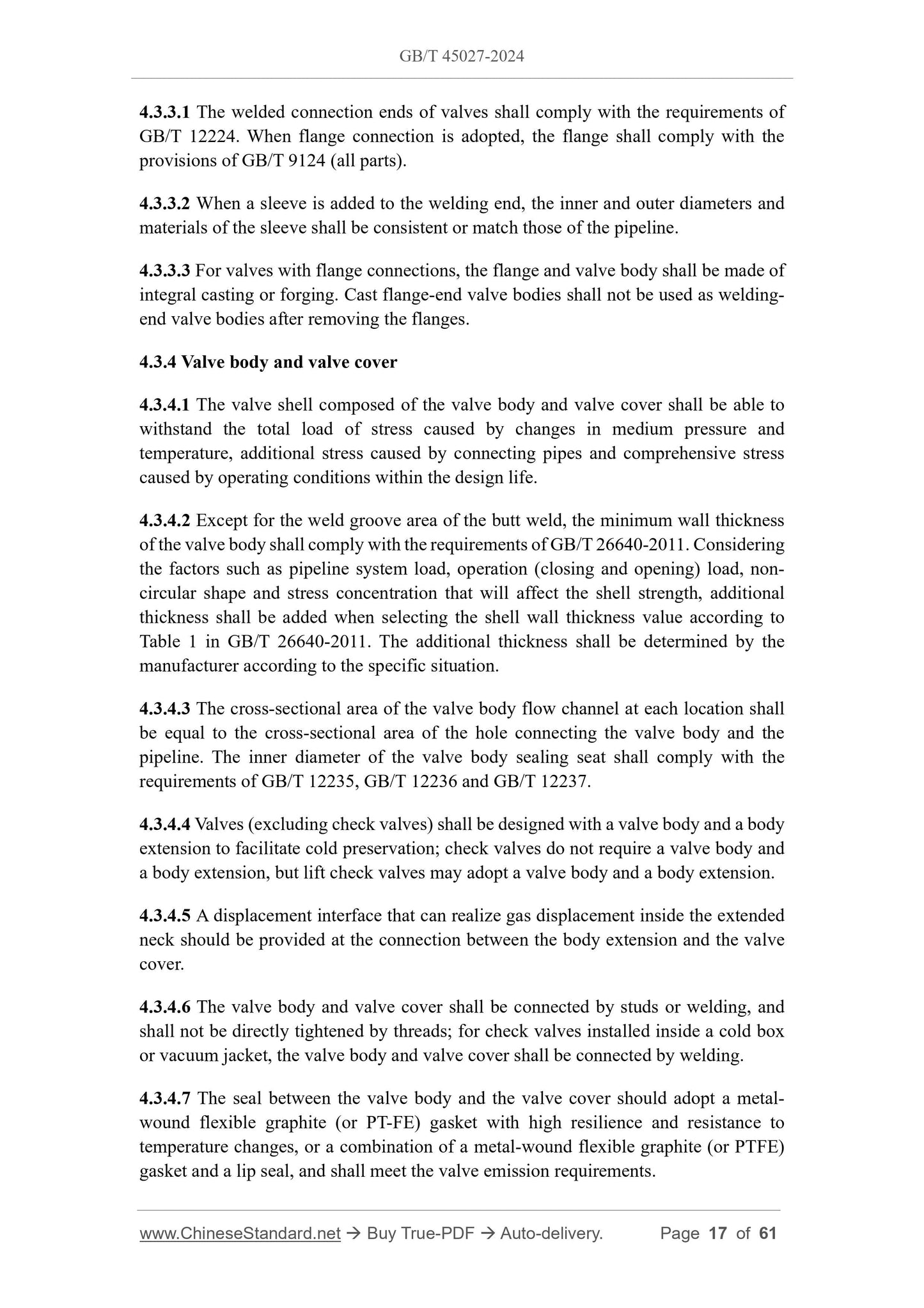
4.3.3.1 The welded connection ends of valves shall comply with the requirements of
GB/T 12224.When flange connection is adopted, the flange shall comply with the
provisions of GB/T 9124 (all parts).
4.3.3.2 When a sleeve is added to the welding end, the inner and outer diameters and
materials of the sleeve shall be consistent or match those of the pipeline.
4.3.3.3 For valves with flange connections, the flange and valve body shall be made of
integral casting or forging. Cast flange-end valve bodies shall not be used as welding-
end valve bodies after removing the flanges.
4.3.4 Valve body and valve cover
4.3.4.1 The valve shell composed of the valve body and valve cover shall be able to
withstand the total load of stress caused by changes in medium pressure and
temperature, additional stress caused by connecting pipes and comprehensive stress
caused by operating conditions within the design life.
4.3.4.2 Except for the weld groove area of the butt weld, the minimum wall thickness
of the valve body shall comply with the requirements of GB/T 26640-2011.Considering
the factors such as pipeline system load, operation (closing and opening) load, non-
circular shape and stress concentration that will affect the shell strength, additional
thickness shall be added when selecting the shell wall thickness value according to
Table 1 in GB/T 26640-2011.The additional thickness shall be determined by the
manufacturer according to the specific situation.
4.3.4.3 The cross-sectional area of the valve body flow channel at each location shall
be equal to the cross-sectional area of the hole connecting the valve body and the
pipeline. The inner diameter of the valve body sealing seat shall comply with the
requirements of GB/T 12235, GB/T 12236 and GB/T 12237.
4.3.4.4 Valves (excluding check valves) shall be designed with a valve body and a body
extension to facilitate cold preservation; check valves do not require a valve body and
a body extension, but lift check valves may adopt a valve body and a body extension.
4.3.4.5 A displacement interface that can realize gas displacement inside the extended
neck should be provided at the connection between the body extension and the valve
cover.
4.3.4.6 The valve body and valve cover shall be connected by studs or welding, and
shall not be directly tightened by threads; for check valves installed inside a cold box
or vacuum jacket, the valve body and valve cover shall be connected by welding.
4.3.4.7 The seal between the valve body and the valve cover should adopt a metal-
wound flexible graphite (or PT-FE) gasket with high resilience and resistance to
temperature changes, or a combination of a metal-wound flexible graphite (or PTFE)
gasket and a lip seal, and shall meet the valve emission requirements.
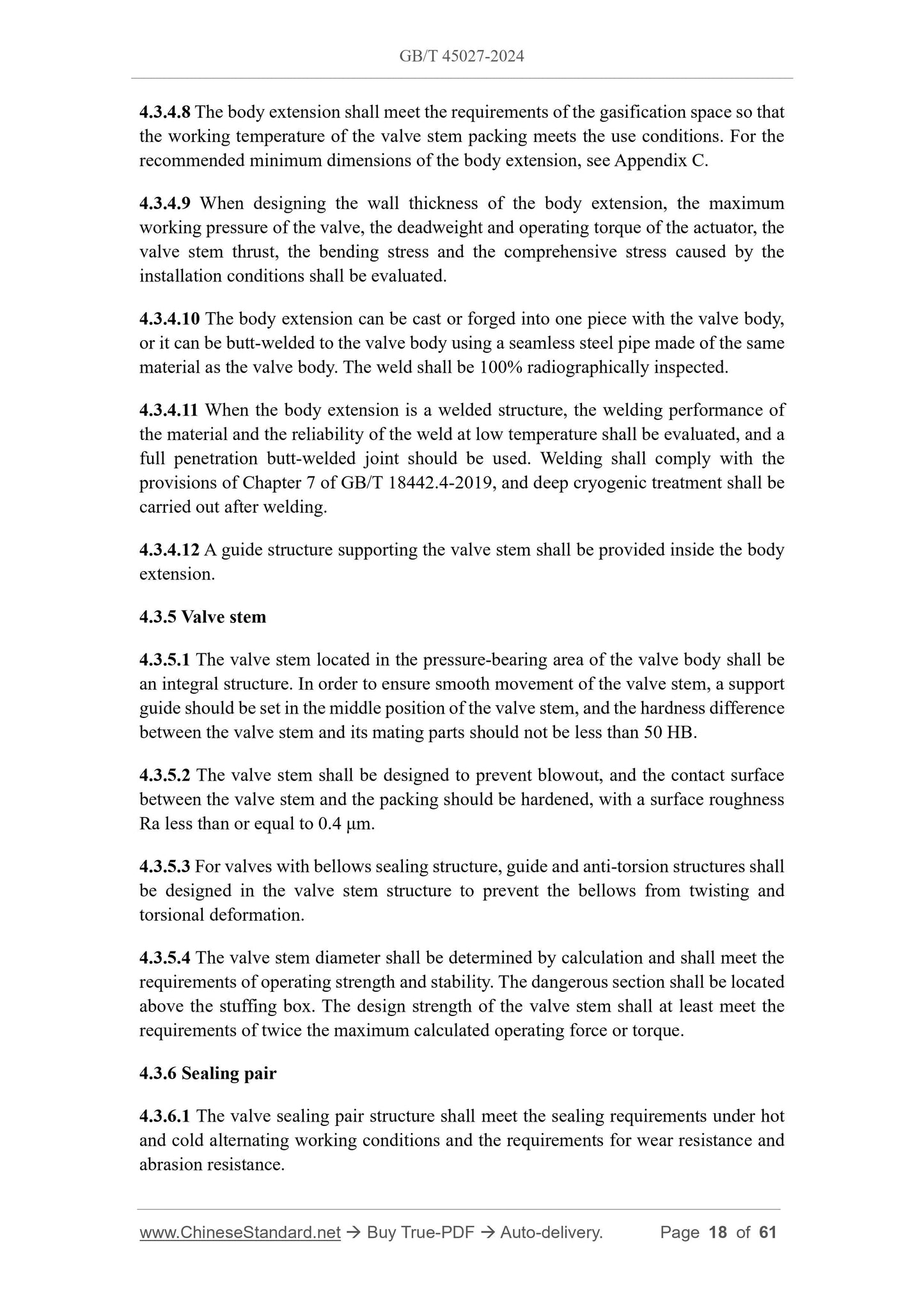
4.3.4.8 The body extension shall meet the requirements of the gasification space so that
the working temperature of the valve stem packing meets the use conditions. For the
recommended minimum dimensions of the body extension, see Appendix C.
4.3.4.9 When designing the wall thickness of the body extension, the maximum
working pressure of the valve, the deadweight and operating torque of the actuator, the
valve stem thrust, the bending stress and the comprehensive stress caused by the
installation conditions shall be evaluated.
4.3.4.10 The body extension can be cast or forged into one piece with the valve body,
or it can be butt-welded to the valve body using a seamless steel pipe made of the same
material as the valve body. The weld shall be 100% radiographically inspected.
4.3.4.11 When the body extension is a welded structure, the welding performance of
the material and the reliability of the weld at low temperature shall be evaluated, and a
full penetration butt-welded joint should be used. Welding shall comply with the
provisions of Chapter 7 of GB/T 18442.4-2019, and deep cryogenic treatment shall be
carried out after welding.
4.3.4.12 A guide structure supporting the valve stem shall be provided inside the body
extension.
4.3.5 Valve stem
4.3.5.1 The valve stem located in the pressure-bearing area of the valve body shall be
an integral structure. In order to ensure smooth movement of the valve stem, a support
guide should be set in the middle position of the valve stem, and the hardness difference
between the valve stem and its mating parts should not be less than 50 HB.
4.3.5.2 The valve stem shall be designed to prevent blowout, and the contact surface
between the valve stem and the packing should be hardened, with a surface roughness
Ra less than or equal to 0.4 μm.
4.3.5.3 For valves with bellows sealing structure, guide and anti-torsion structures shall
be designed in the valve stem structure to prevent the bellows from twisting and
torsional deformation.
4.3.5.4 The valve stem diameter shall be determined by calculation and shall meet the
requirements of operating strength and stability. The dangerous section shall be located
above the stuffing box. The design strength of the valve stem shall at least meet the
requirements of twice the maximum calculated operating force or torque.
4.3.6 Sealing pair
4.3.6.1 The valve sealing pair structure shall meet the sealing requirements under hot
and cold alternating working conditions and the requirements for wear resistance and
abrasion resistance.
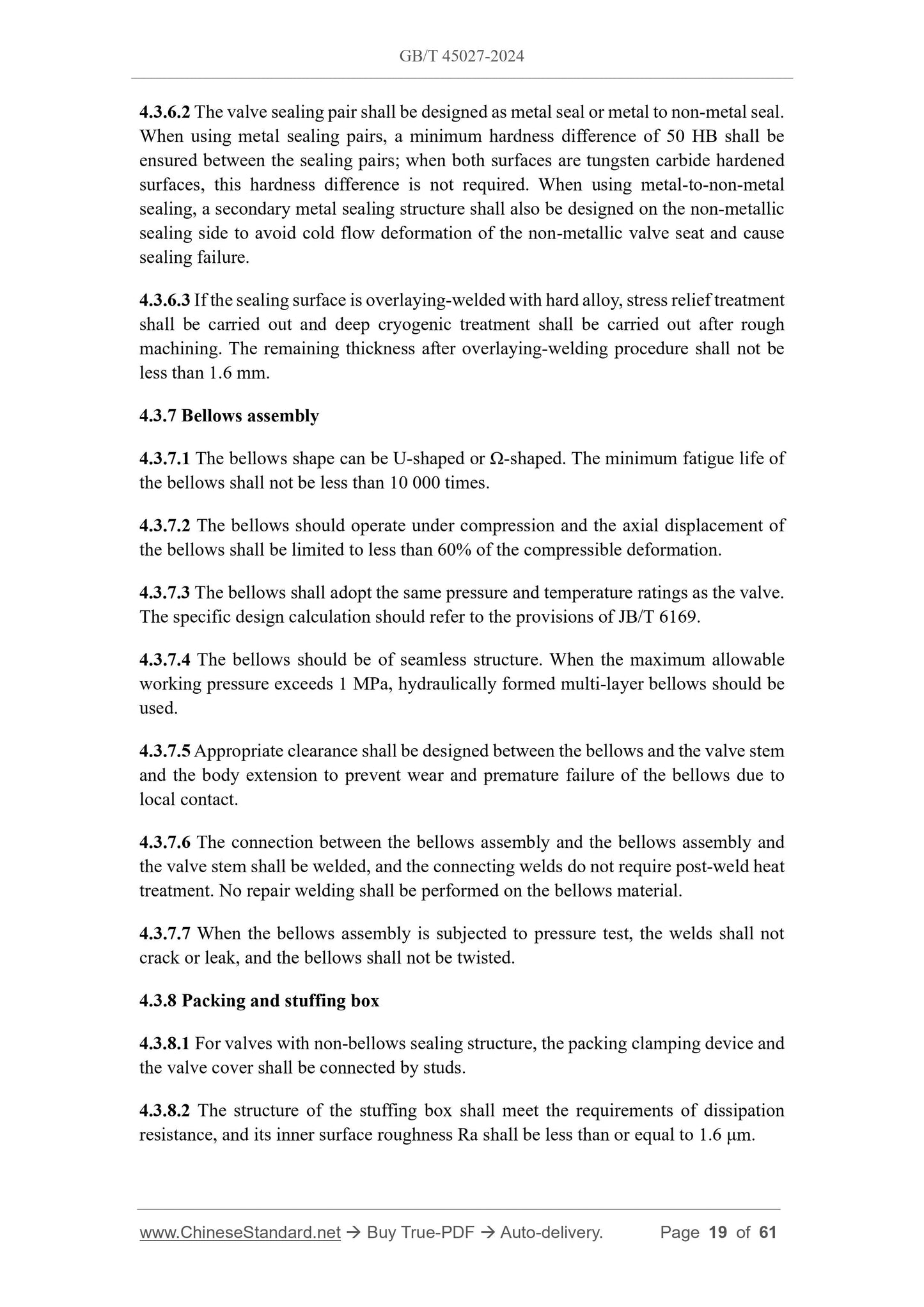
4.3.6.2 The valve sealing pair shall be designed as metal seal or metal to non-metal seal.
When using metal sealing pairs, a ...
Share