1
/
of
10
www.ChineseStandard.us -- Field Test Asia Pte. Ltd.
GB/T 44993-2024 English PDF (GB/T44993-2024)
Regular price
$320.00
Regular price
Sale price
$320.00
Unit price
/
per
Shipping calculated at checkout.
Couldn't load pickup availability
GB/T 44993-2024: On-site testing instruments of off-board charger for electric vehicles
Delivery: 9 seconds. Download (and Email) true-PDF + Invoice.
Get Quotation: Click GB/T 44993-2024 (Self-service in 1-minute)
Newer / historical versions: GB/T 44993-2024
Preview True-PDF (Reload/Scroll-down if blank)
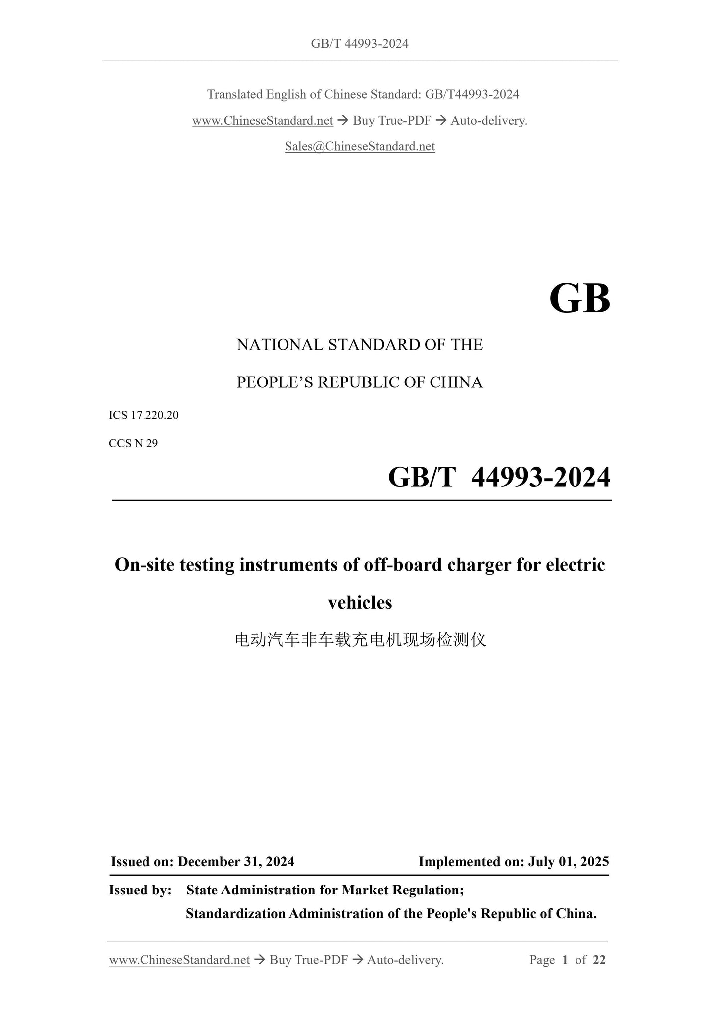
GB/T 44993-2024
GB
NATIONAL STANDARD OF THE
PEOPLE’S REPUBLIC OF CHINA
ICS 17.220.20
CCS N 29
On-site testing instruments of off-board charger for electric
vehicles
ISSUED ON. DECEMBER 31, 2024
IMPLEMENTED ON. JULY 01, 2025
Issued by. State Administration for Market Regulation;
Standardization Administration of the People's Republic of China.
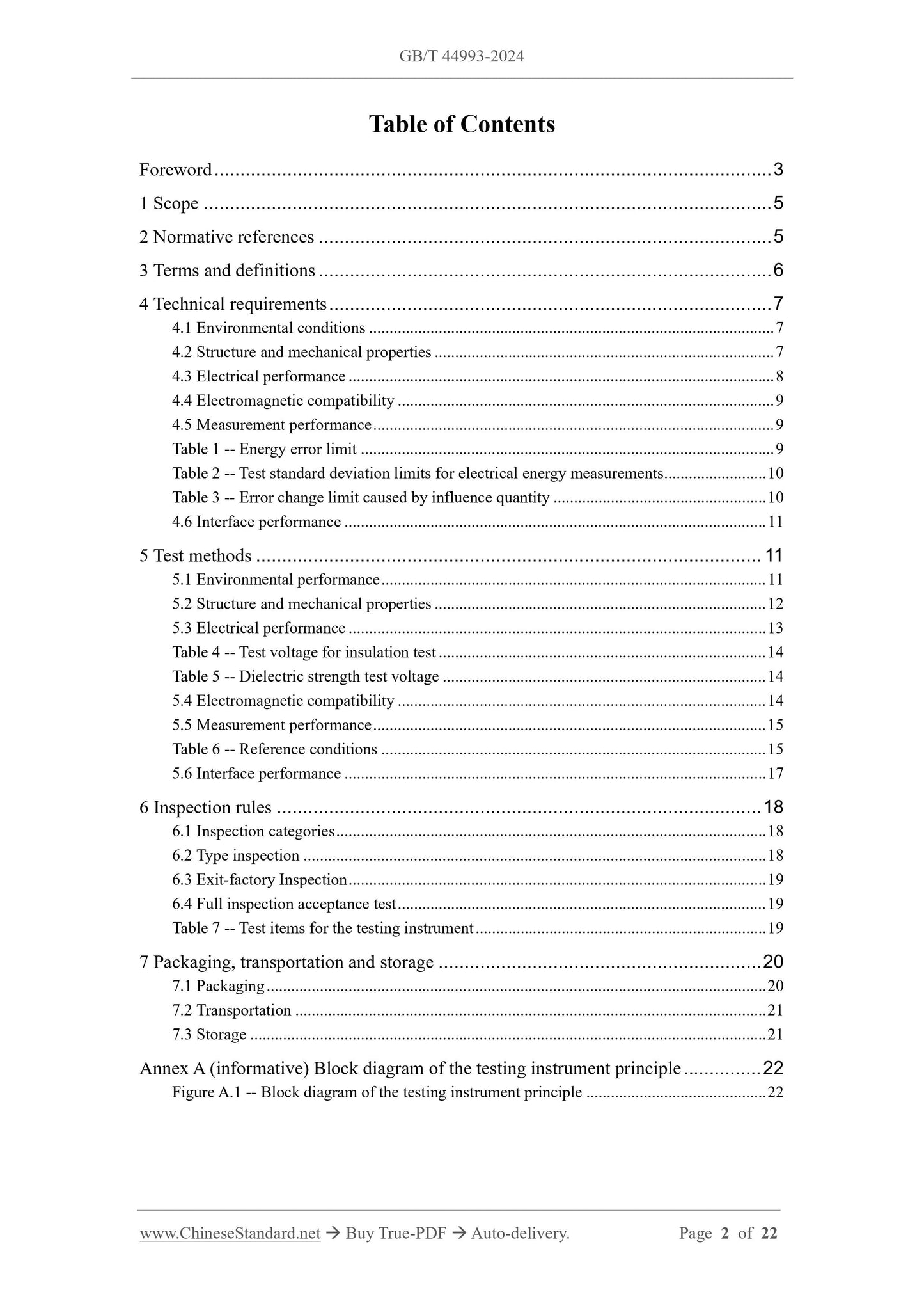
Table of Contents
Foreword... 3
1 Scope... 5
2 Normative references... 5
3 Terms and definitions... 6
4 Technical requirements... 7
4.1 Environmental conditions... 7
4.2 Structure and mechanical properties... 7
4.3 Electrical performance... 8
4.4 Electromagnetic compatibility... 9
4.5 Measurement performance... 9
Table 1 -- Energy error limit... 9
Table 2 -- Test standard deviation limits for electrical energy measurements... 10
Table 3 -- Error change limit caused by influence quantity... 10
4.6 Interface performance... 11
5 Test methods... 11
5.1 Environmental performance... 11
5.2 Structure and mechanical properties... 12
5.3 Electrical performance... 13
Table 4 -- Test voltage for insulation test... 14
Table 5 -- Dielectric strength test voltage... 14
5.4 Electromagnetic compatibility... 14
5.5 Measurement performance... 15
Table 6 -- Reference conditions... 15
5.6 Interface performance... 17
6 Inspection rules... 18
6.1 Inspection categories... 18
6.2 Type inspection... 18
6.3 Exit-factory Inspection... 19
6.4 Full inspection acceptance test... 19
Table 7 -- Test items for the testing instrument... 19
7 Packaging, transportation and storage... 20
7.1 Packaging... 20
7.2 Transportation... 21
7.3 Storage... 21
Annex A (informative) Block diagram of the testing instrument principle... 22
Figure A.1 -- Block diagram of the testing instrument principle... 22
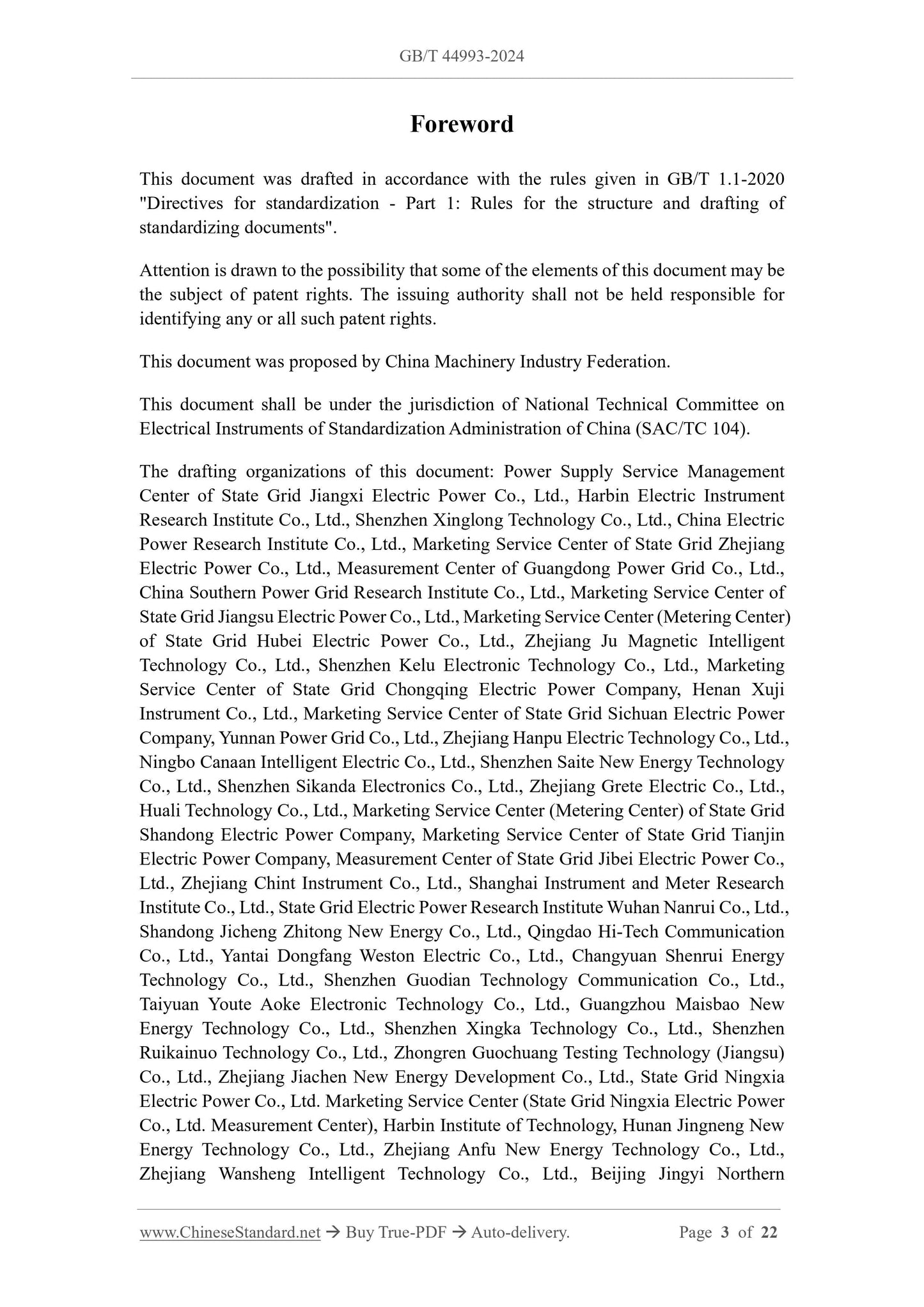
Foreword
This document was drafted in accordance with the rules given in GB/T 1.1-2020
"Directives for standardization - Part 1.Rules for the structure and drafting of
standardizing documents".
Attention is drawn to the possibility that some of the elements of this document may be
the subject of patent rights. The issuing authority shall not be held responsible for
identifying any or all such patent rights.
This document was proposed by China Machinery Industry Federation.
This document shall be under the jurisdiction of National Technical Committee on
Electrical Instruments of Standardization Administration of China (SAC/TC 104).
The drafting organizations of this document. Power Supply Service Management
Center of State Grid Jiangxi Electric Power Co., Ltd., Harbin Electric Instrument
Research Institute Co., Ltd., Shenzhen Xinglong Technology Co., Ltd., China Electric
Power Research Institute Co., Ltd., Marketing Service Center of State Grid Zhejiang
Electric Power Co., Ltd., Measurement Center of Guangdong Power Grid Co., Ltd.,
China Southern Power Grid Research Institute Co., Ltd., Marketing Service Center of
State Grid Jiangsu Electric Power Co., Ltd., Marketing Service Center (Metering Center)
of State Grid Hubei Electric Power Co., Ltd., Zhejiang Ju Magnetic Intelligent
Technology Co., Ltd., Shenzhen Kelu Electronic Technology Co., Ltd., Marketing
Service Center of State Grid Chongqing Electric Power Company, Henan Xuji
Instrument Co., Ltd., Marketing Service Center of State Grid Sichuan Electric Power
Company, Yunnan Power Grid Co., Ltd., Zhejiang Hanpu Electric Technology Co., Ltd.,
Ningbo Canaan Intelligent Electric Co., Ltd., Shenzhen Saite New Energy Technology
Co., Ltd., Shenzhen Sikanda Electronics Co., Ltd., Zhejiang Grete Electric Co., Ltd.,
Huali Technology Co., Ltd., Marketing Service Center (Metering Center) of State Grid
Shandong Electric Power Company, Marketing Service Center of State Grid Tianjin
Electric Power Company, Measurement Center of State Grid Jibei Electric Power Co.,
Ltd., Zhejiang Chint Instrument Co., Ltd., Shanghai Instrument and Meter Research
Institute Co., Ltd., State Grid Electric Power Research Institute Wuhan Nanrui Co., Ltd.,
Shandong Jicheng Zhitong New Energy Co., Ltd., Qingdao Hi-Tech Communication
Co., Ltd., Yantai Dongfang Weston Electric Co., Ltd., Changyuan Shenrui Energy
Technology Co., Ltd., Shenzhen Guodian Technology Communication Co., Ltd.,
Taiyuan Youte Aoke Electronic Technology Co., Ltd., Guangzhou Maisbao New
Energy Technology Co., Ltd., Shenzhen Xingka Technology Co., Ltd., Shenzhen
Ruikainuo Technology Co., Ltd., Zhongren Guochuang Testing Technology (Jiangsu)
Co., Ltd., Zhejiang Jiachen New Energy Development Co., Ltd., State Grid Ningxia
Electric Power Co., Ltd. Marketing Service Center (State Grid Ningxia Electric Power
Co., Ltd. Measurement Center), Harbin Institute of Technology, Hunan Jingneng New
Energy Technology Co., Ltd., Zhejiang Anfu New Energy Technology Co., Ltd.,
Zhejiang Wansheng Intelligent Technology Co., Ltd., Beijing Jingyi Northern
On-site testing instruments of off-board charger for electric
vehicles
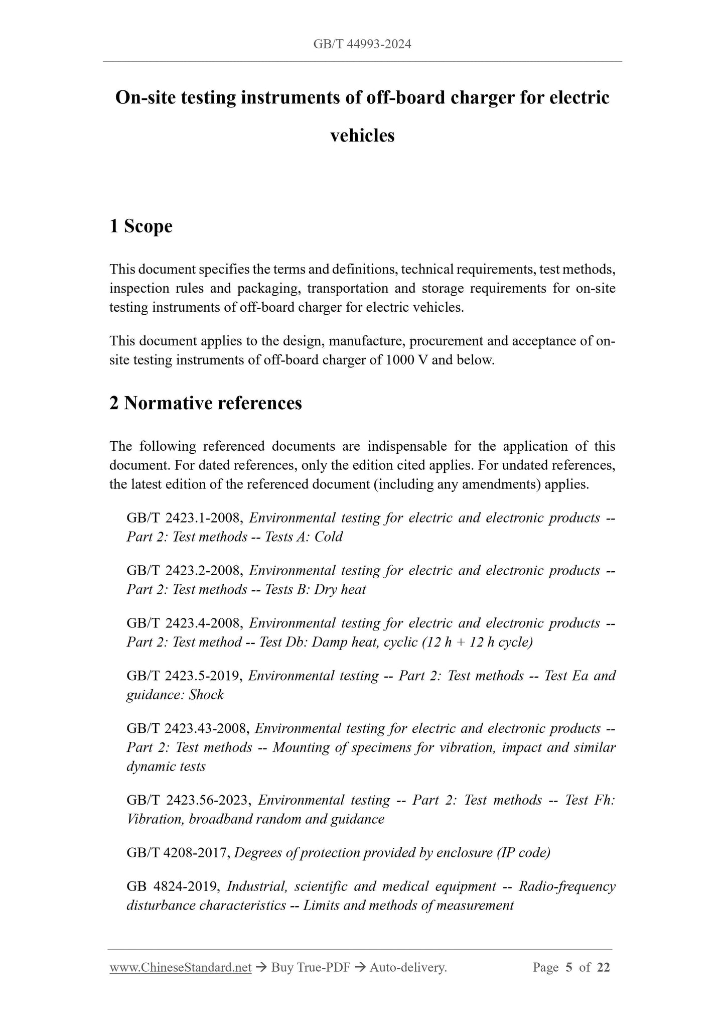
1 Scope
This document specifies the terms and definitions, technical requirements, test methods,
inspection rules and packaging, transportation and storage requirements for on-site
testing instruments of off-board charger for electric vehicles.
This document applies to the design, manufacture, procurement and acceptance of on-
site testing instruments of off-board charger of 1000 V and below.
2 Normative references
The following referenced documents are indispensable for the application of this
document. For dated references, only the edition cited applies. For undated references,
the latest edition of the referenced document (including any amendments) applies.
GB/T 2423.1-2008, Environmental testing for electric and electronic products --
Part 2.Test methods -- Tests A. Cold
GB/T 2423.2-2008, Environmental testing for electric and electronic products --
Part 2.Test methods -- Tests B. Dry heat
GB/T 2423.4-2008, Environmental testing for electric and electronic products --
Part 2.Test method -- Test Db. Damp heat, cyclic (12 h + 12 h cycle)
GB/T 2423.5-2019, Environmental testing -- Part 2.Test methods -- Test Ea and
guidance. Shock
GB/T 2423.43-2008, Environmental testing for electric and electronic products --
Part 2.Test methods -- Mounting of specimens for vibration, impact and similar
dynamic tests
GB/T 2423.56-2023, Environmental testing -- Part 2.Test methods -- Test Fh.
Vibration, broadband random and guidance
GB/T 4208-2017, Degrees of protection provided by enclosure (IP code)
GB 4824-2019, Industrial, scientific and medical equipment -- Radio-frequency
disturbance characteristics -- Limits and methods of measurement
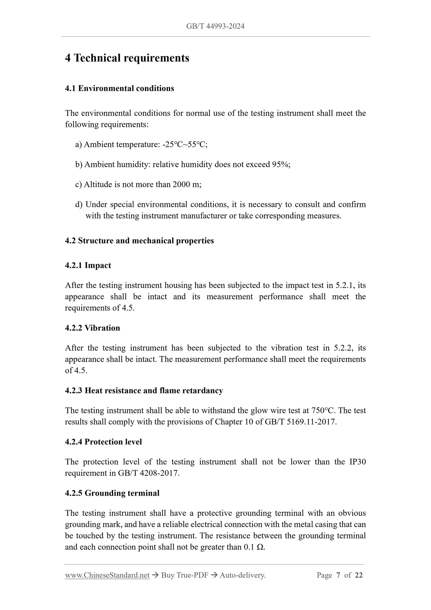
4 Technical requirements
4.1 Environmental conditions
The environmental conditions for normal use of the testing instrument shall meet the
following requirements.
a) Ambient temperature. -25℃~55℃;
b) Ambient humidity. relative humidity does not exceed 95%;
c) Altitude is not more than 2000 m;
d) Under special environmental conditions, it is necessary to consult and confirm
with the testing instrument manufacturer or take corresponding measures.
4.2 Structure and mechanical properties
4.2.1 Impact
After the testing instrument housing has been subjected to the impact test in 5.2.1, its
appearance shall be intact and its measurement performance shall meet the
requirements of 4.5.
4.2.2 Vibration
After the testing instrument has been subjected to the vibration test in 5.2.2, its
appearance shall be intact. The measurement performance shall meet the requirements
of 4.5.
4.2.3 Heat resistance and flame retardancy
The testing instrument shall be able to withstand the glow wire test at 750°C. The test
results shall comply with the provisions of Chapter 10 of GB/T 5169.11-2017.
4.2.4 Protection level
The protection level of the testing instrument shall not be lower than the IP30
requirement in GB/T 4208-2017.
4.2.5 Grounding terminal
The testing instrument shall have a protective grounding terminal with an obvious
grounding mark, and have a reliable electrical connection with the metal casing that can
be touched by the testing instrument. The resistance between the grounding terminal
and each connection point shall not be greater than 0.1 Ω.
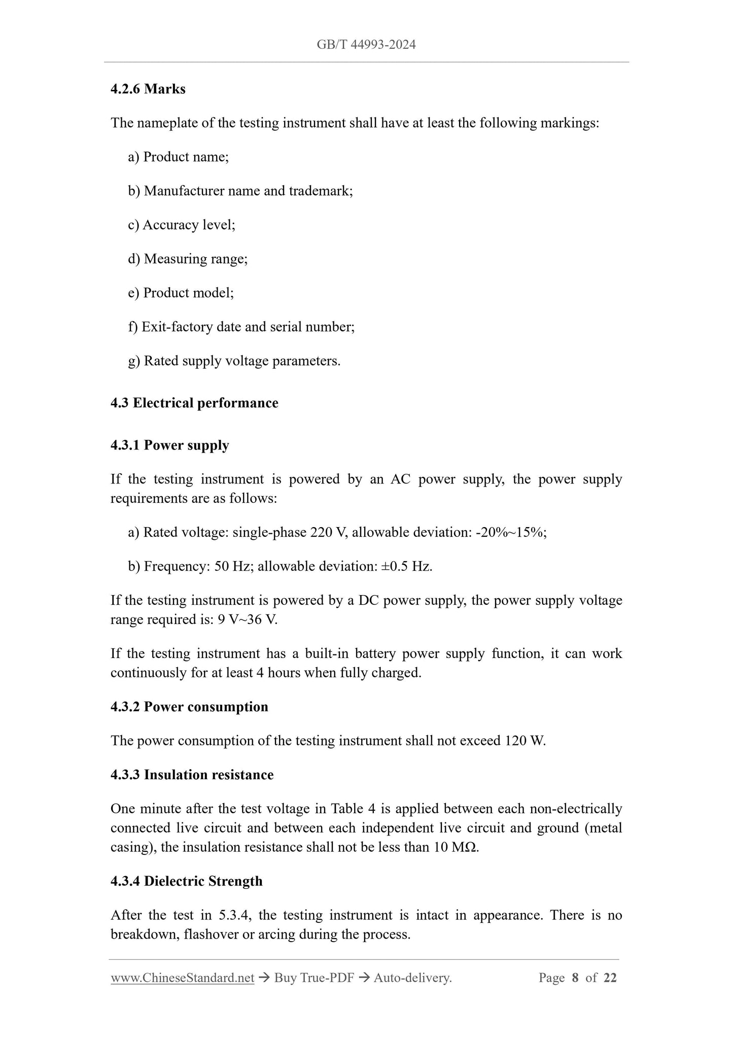
4.2.6 Marks
The nameplate of the testing instrument shall have at least the following markings.
a) Product name;
b) Manufacturer name and trademark;
c) Accuracy level;
d) Measuring range;
e) Product model;
f) Exit-factory date and serial number;
g) Rated supply voltage parameters.
4.3 Electrical performance
4.3.1 Power supply
If the testing instrument is powered by an AC power supply, the power supply
requirements are as follows.
a) Rated voltage. single-phase 220 V, allowable deviation. -20%~15%;
b) Frequency. 50 Hz; allowable deviation. ±0.5 Hz.
If the testing instrument is powered by a DC power supply, the power supply voltage
range required is. 9 V~36 V.
If the testing instrument has a built-in battery power supply function, it can work
continuously for at least 4 hours when fully charged.
4.3.2 Power consumption
The power consumption of the testing instrument shall not exceed 120 W.
4.3.3 Insulation resistance
One minute after the test voltage in Table 4 is applied between each non-electrically
connected live circuit and between each independent live circuit and ground (metal
casing), the insulation resistance shall not be less than 10 MΩ.
4.3.4 Dielectric Strength
After the test in 5.3.4, the testing instrument is intact in appearance. There is no
breakdown, flashover or arcing during the process.
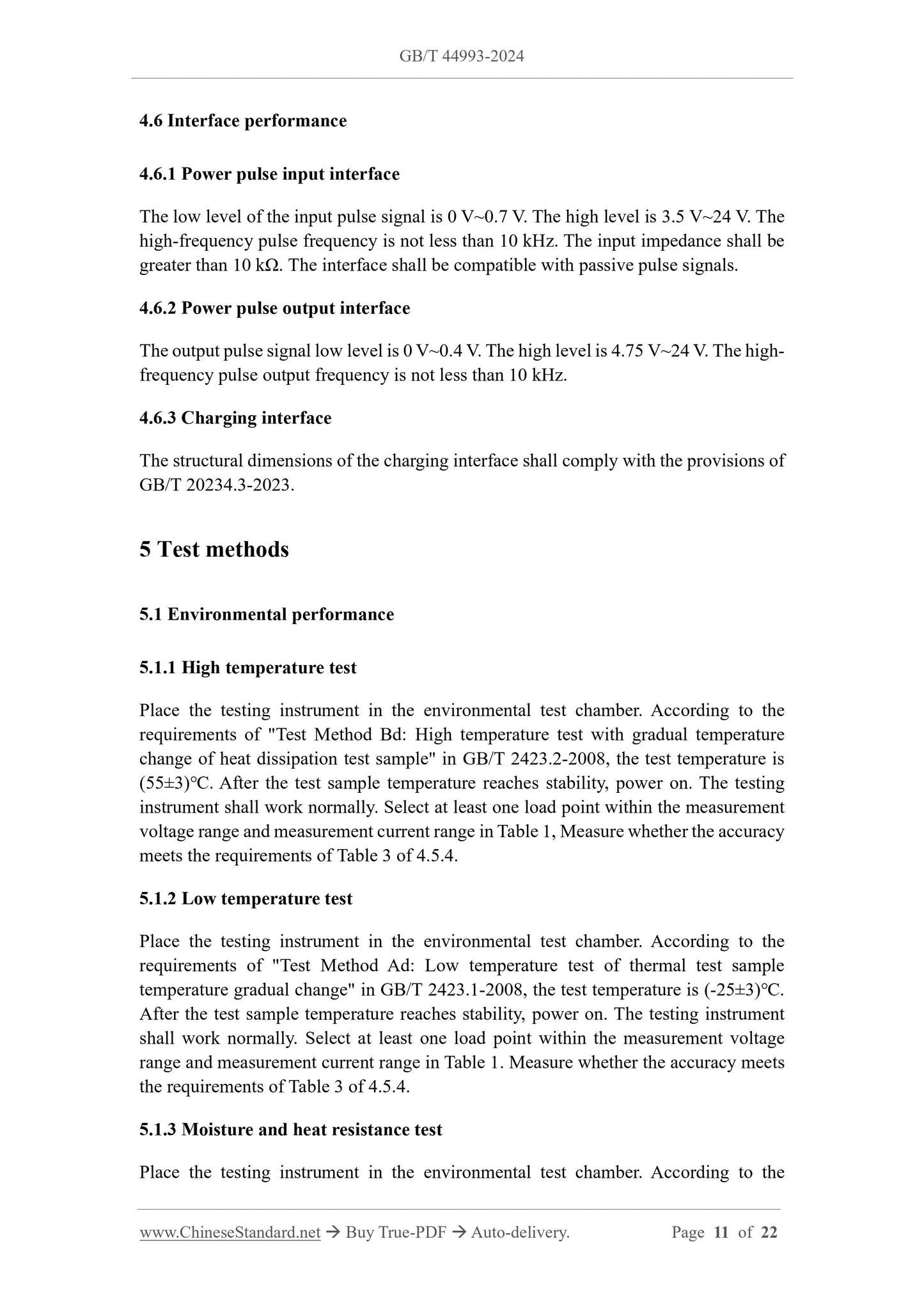
4.6 Interface performance
4.6.1 Power pulse input interface
The low level of the input pulse signal is 0 V~0.7 V. The high level is 3.5 V~24 V. The
high-frequency pulse frequency is not less than 10 kHz. The input impedance shall be
greater than 10 kΩ. The interface shall be compatible with passive pulse signals.
4.6.2 Power pulse output interface
The output pulse signal low level is 0 V~0.4 V. The high level is 4.75 V~24 V. The high-
frequency pulse output frequency is not less than 10 kHz.
4.6.3 Charging interface
The structural dimensions of the charging interface shall comply with the provisions of
GB/T 20234.3-2023.
5 Test methods
5.1 Environmental performance
5.1.1 High temperature test
Place the testing instrument in the environmental test chamber. According to the
requirements of "Test Method Bd. High temperature test with gradual temperature
change of heat dissipation test sample" in GB/T 2423.2-2008, the test temperature is
(55±3)℃. After the test sample temperature reaches stability, power on. The testing
instrument shall work normally. Select at least one load point within the measurement
voltage range and measurement current range in Table 1, Measure whether the accuracy
meets the requirements of Table 3 of 4.5.4.
5.1.2 Low temperature test
Place the testing instrument in the environmental test chamber. According to the
requirements of "Test Method Ad. Low temperature test of thermal test sample
temperature gradual change" in GB/T 2423.1-2008, the test temperature is (-25±3)℃.
After the test sample temperature reaches stability, power on. The testing instrument
shall work normally. Select at least one load point within the measurement voltage
range and measurement current range in Table 1.Measure whether the accuracy meets
the requirements of Table 3 of 4.5.4.
5.1.3 Moisture and heat resistance test
Place the testing instrument in the environmental test chamber. According to the
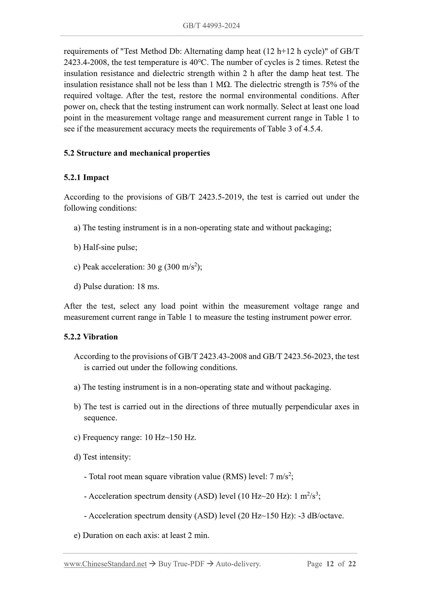
requirements of "Test Method Db. Alternating damp heat (12 h+12 h cycle)" of GB/T
2423.4-2008, the test temperature is 40℃. The number of cycles is 2 times. Retest the
insulation resistance and dielectric strength within 2 h after the damp heat test. The
insulation resistance shall not be less than 1 MΩ. The dielectric strength is 75% of the
required voltage. After the test, restore the normal environmental conditions. After
power on, check that the testing instrument can work normally. Select at least one load
point in the measurement voltage range and measurement current range in Table 1 to
see if the measurement accuracy meets the requirements of Table 3 of 4.5.4.
5.2 Structure and mechanical properties
5.2.1 Impact
According to the provisions of GB/T 2423.5-2019, the test is carried out under the
following conditions.
a) The testing instrument is in a non-operating state and without packaging;
b) Half-sine pulse;
c) Peak acceleration. 30 g (300 m/s2);
d) Pulse duration. 18 ms.
After the test, select any load point within the measurement voltage range and
measurement current range in Table 1 to measure the testing instrument power error.
5.2.2 Vibration
According to the provisions of GB/T 2423.43-2008 and GB/T 2423.56-2023, the test
is carried out under the following conditions.
a) The testing instrument is in a non-operating state and without packaging.
b) The test is carried out in the directions of three mutually perpendicular axes in
sequence.
c) Frequency range. 10 Hz~150 Hz.
d) Test intensity.
- Total root mean square vibration value (RMS) level. 7 m/s2;
- Acceleration spectrum density (ASD) level (10 Hz~20 Hz). 1 m2/s3;
- Acceleration spectrum density (ASD) level (20 Hz~150 Hz). -3 dB/octave.
e) Duration on each axis. at least 2 min.
Use an instrument with a resistance measurement tolerance limit of no more than ±1%.
Measure the impedance of the pulse input terminal and check if the resistance is greater
than 10 kΩ.
Short-circuit the pulse input line of the testing instrument. Check if the testing
instrument can correctly record a pulse.
5.6.2 Power pulse output interface test
Use an oscilloscope with an amplitude measurement error limit of no more than ±2%
to measure the low-level and high-level signals of the output waveform of the electric
energy pulse output interface.
5.6.3 Charging interface test
Use a tool such as a vernier caliper with an accuracy of 0.01 mm to measure the
interf...
Share