1
/
of
7
www.ChineseStandard.us -- Field Test Asia Pte. Ltd.
GB/T 44553-2024 English PDF (GB/T44553-2024)
Regular price
$215.00
Regular price
Sale price
$215.00
Unit price
/
per
Shipping calculated at checkout.
Couldn't load pickup availability
GB/T 44553-2024: Technical specification for energy-saving of hot-dip galvanizing thermal system for steel tubes
Delivery: 9 seconds. Download (& Email) true-PDF + Invoice.
Get Quotation: Click GB/T 44553-2024 (Self-service in 1-minute)
Historical versions (Master-website): GB/T 44553-2024
Preview True-PDF (Reload/Scroll-down if blank)
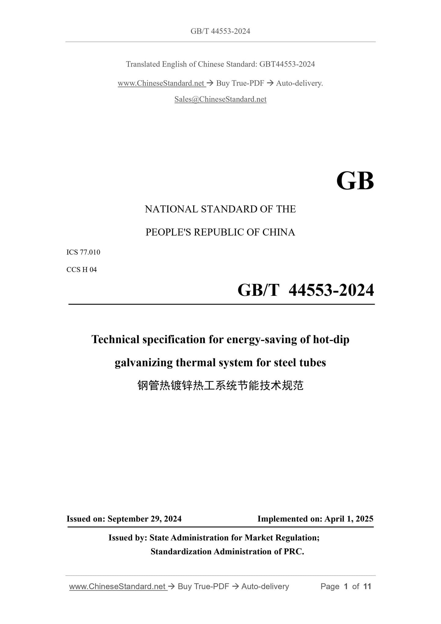
GB/T 44553-2024
GB
NATIONAL STANDARD OF THE
PEOPLE'S REPUBLIC OF CHINA
ICS 77.010
CCS H 04
Technical specification for energy-saving of hot-dip
galvanizing thermal system for steel tubes
ISSUED ON: SEPTEMBER 29, 2024
IMPLEMENTED ON: APRIL 1, 2025
Issued by: State Administration for Market Regulation;
Standardization Administration of PRC.
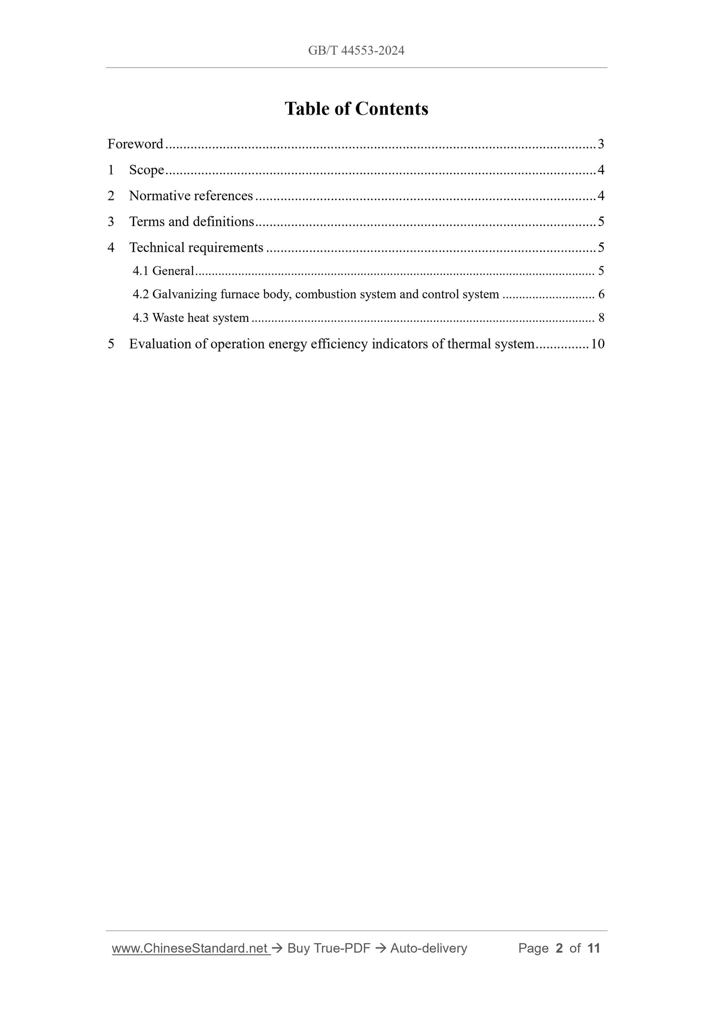
Table of Contents
Foreword ... 3
1 Scope ... 4
2 Normative references ... 4
3 Terms and definitions ... 5
4 Technical requirements ... 5
4.1 General ... 5
4.2 Galvanizing furnace body, combustion system and control system ... 6
4.3 Waste heat system ... 8
5 Evaluation of operation energy efficiency indicators of thermal system ... 10
Technical specification for energy-saving of hot-dip
galvanizing thermal system for steel tubes
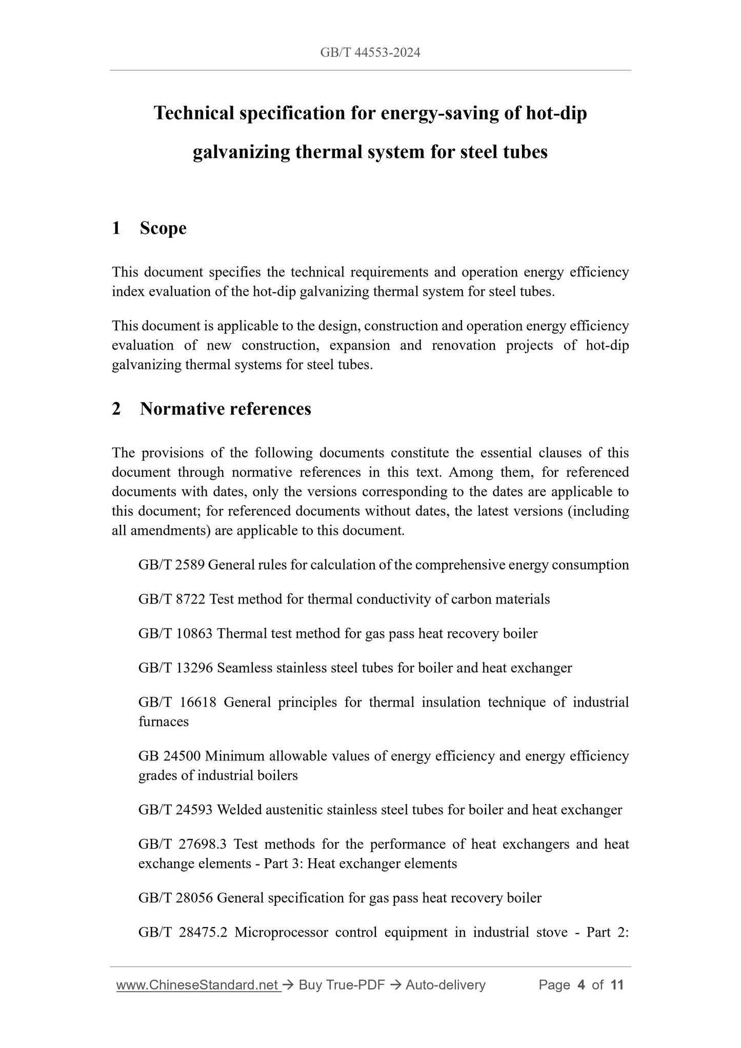
1 Scope
This document specifies the technical requirements and operation energy efficiency
index evaluation of the hot-dip galvanizing thermal system for steel tubes.
This document is applicable to the design, construction and operation energy efficiency
evaluation of new construction, expansion and renovation projects of hot-dip
galvanizing thermal systems for steel tubes.
2 Normative references
The provisions of the following documents constitute the essential clauses of this
document through normative references in this text. Among them, for referenced
documents with dates, only the versions corresponding to the dates are applicable to
this document; for referenced documents without dates, the latest versions (including
all amendments) are applicable to this document.
GB/T 2589 General rules for calculation of the comprehensive energy consumption
GB/T 8722 Test method for thermal conductivity of carbon materials
GB/T 10863 Thermal test method for gas pass heat recovery boiler
GB/T 13296 Seamless stainless steel tubes for boiler and heat exchanger
GB/T 16618 General principles for thermal insulation technique of industrial
furnaces
GB 24500 Minimum allowable values of energy efficiency and energy efficiency
grades of industrial boilers
GB/T 24593 Welded austenitic stainless steel tubes for boiler and heat exchanger
GB/T 27698.3 Test methods for the performance of heat exchangers and heat
exchange elements - Part 3: Heat exchanger elements
GB/T 28056 General specification for gas pass heat recovery boiler
GB/T 28475.2 Microprocessor control equipment in industrial stove - Part 2:
steam in the heat recovery steam generator to blow the inner wall of the steel tube and
dry the galvanized steel tube. The excess steam heats the solvent and pickling medium
(hydrochloric acid or sulfuric acid) in the heat exchanger, or heats the circulating water
and then heats the solvent and pickling medium (hydrochloric acid or sulfuric acid) in
the heat exchanger. If there is excess heat, it is transported to the office area and living
area for use.
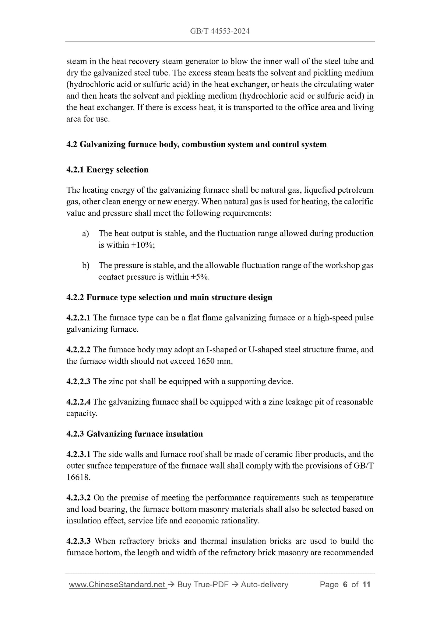
4.2 Galvanizing furnace body, combustion system and control system
4.2.1 Energy selection
The heating energy of the galvanizing furnace shall be natural gas, liquefied petroleum
gas, other clean energy or new energy. When natural gas is used for heating, the calorific
value and pressure shall meet the following requirements:
a) The heat output is stable, and the fluctuation range allowed during production
is within ±10%;
b) The pressure is stable, and the allowable fluctuation range of the workshop gas
contact pressure is within ±5%.
4.2.2 Furnace type selection and main structure design
4.2.2.1 The furnace type can be a flat flame galvanizing furnace or a high-speed pulse
galvanizing furnace.
4.2.2.2 The furnace body may adopt an I-shaped or U-shaped steel structure frame, and
the furnace width should not exceed 1650 mm.
4.2.2.3 The zinc pot shall be equipped with a supporting device.
4.2.2.4 The galvanizing furnace shall be equipped with a zinc leakage pit of reasonable
capacity.
4.2.3 Galvanizing furnace insulation
4.2.3.1 The side walls and furnace roof shall be made of ceramic fiber products, and the
outer surface temperature of the furnace wall shall comply with the provisions of GB/T
16618.
4.2.3.2 On the premise of meeting the performance requirements such as temperature
and load bearing, the furnace bottom masonry materials shall also be selected based on
insulation effect, service life and economic rationality.
4.2.3.3 When refractory bricks and thermal insulation bricks are used to build the
furnace bottom, the length and width of the refractory brick masonry are recommended
to be integer multiples of 116 mm, and the masonry height is recommended to be an
integer multiple of 68 mm.
4.2.3.4 When refractory castables are used to cast the furnace bottom as a whole, the
temperature and load-bearing requirements shall be met.
4.2.4 Galvanizing furnace heat load
4.2.4.1 The zinc capacity of the zinc pot should be 15~20 times the designed production
capacity per unit time.
4.2.4.2 The average heating intensity of the zinc pot wall shall not be less than 24
kW/(m2 • h).
4.2.4.3 The combustion device of appropriate specifications shall be selected according
to the type and structural size of the galvanizing furnace, heating process, fuel type,
heat load size and environmental protection requirements.
4.2.4.4 The heat supply of the galvanizing furnace shall be determined by heat balance
calculation or selected according to empirical data.
4.2.4.5 The maximum heat load of the galvanizing furnace shall not exceed 1.3 times
the rated heat load.
4.2.5 Energy saving of galvanizing furnace
4.2.5.1 The exhaust gas temperature of the galvanizing furnace should not exceed
600 ℃, and the waste heat shall be recycled.
4.2.5.2 It is recommended to use a computer control system for the thermal system of
the galvanizing furnace and effectively control the zinc liquid temperature according to
the heating model.
4.2.6 Combustion system configuration of galvanizing furnace
4.2.6.1 The combustion system shall include low NOx burners, gas regulating valves,
monitoring systems, induced draft fans and temperature sensors, and be equipped with
automatic ignition and flame monitoring devices.
4.2.6.2 The burners of the flat flame galvanizing furnace shall be arranged reasonably
according to the combustion chamber, the influence of temperature uniformity and the
smoke exhaust method.
4.2.6.3 The center line of the burner of the high-speed pulse galvanizing furnace shall
be arranged vertically on the center line of the fire channel.
4.2.6.4 The combustion system shall be equipped with a main shut-off valve with alarm
4.3.2 Waste heat system process design
4.3.2.1 When designing the process for collecting and utilizing the waste heat of the
production line, energy-saving factors shall be considered, including fully collecting
and utilizing the waste heat from production line combustion and workpiece cooling.
4.3.2.2 In the waste heat collection system, the waste heat collection equipment and
automatic control system are used to automatically collect or utilize the waste heat from
the production line online.
4.3.2.3 The waste heat utilization system uses the collected heat for drying, heating and
steam production required by other processes, as well as office life, etc. until the heat
energy is fully utilized.
4.3.3 Waste heat collection equipment
4.3.3.1 Waste heat collection equipment shall include heat recovery steam generator,
pipelines, control system, accessories and instruments, etc.
4.3.3.2 The design and selection of flue-type heat recovery steam generators shall
comply with the requirements of GB/T 28056, YB/T 4483 and JB/T 7603.
4.3.3.3 The design and material selection of pipelines shall comply with the provisions
of YB/T 4483. The pipeline surface shall have a thermal insulation layer, and the design
of the thermal insulation layer shall comply with the provisions of GB 50126.
4.3.3.4 The design and selection of accessories and instruments for flue-type heat
recovery steam generators shall comply with the provisions of YB/T 4483.
4.3.3.5 The thermal efficiency of the heat recovery steam generator shall not be less
than 80%.
4.3.4 Waste heat utilization equipment
4.3.4.1 The heat exchange system shall select shell-and-tube polytetrafluoroethylene
heat exchangers, stainless-steel coiled pipe heat exchangers or graphite heat exchangers
according to the application conditions, and be equipped with waste heat collectors,
heat exchangers, pipelines, valve groups and temperature and flow meters.
4.3.4.2 The design and selection of shell-and-tube PTFE heat exchangers shall comply
with the requirements of GB/T 27698.3 and HG/T 4172.
4.3.4.3 Stainless-steel Coiled pipe heat exchangers should use pipes specified in GB/T
13296 or GB/T 24593.
4.3.4.4 The design, thermal conductivity and measurement method of graphite heat
exchangers shall comply with the requirements of GB/T 8722 and HG/T 3187.
GB/T 44553-2024
GB
NATIONAL STANDARD OF THE
PEOPLE'S REPUBLIC OF CHINA
ICS 77.010
CCS H 04
Technical specification for energy-saving of hot-dip
galvanizing thermal system for steel tubes
ISSUED ON: SEPTEMBER 29, 2024
IMPLEMENTED ON: APRIL 1, 2025
Issued by: State Administration for Market Regulation;
Standardization Administration of PRC.
Table of Contents
Foreword ... 3
1 Scope ... 4
2 Normative references ... 4
3 Terms and definitions ... 5
4 Technical requirements ... 5
4.1 General ... 5
4.2 Galvanizing furnace body, combustion system and control system ... 6
4.3 Waste heat system ... 8
5 Evaluation of operation energy efficiency indicators of thermal system ... 10
Technical specification for energy-saving of hot-dip
galvanizing thermal system for steel tubes
1 Scope
This document specifies the technical requirements and operation energy efficiency
index evaluation of the hot-dip galvanizing thermal system for steel tubes.
This document is applicable to the design, construction and operation energy efficiency
evaluation of new construction, expansion and renovation projects of hot-dip
galvanizing thermal systems for steel tubes.
2 Normative references
The provisions of the following documents constitute the essential clauses of this
document through normative references in this text. Among them, for referenced
documents with dates, only the versions corresponding to the dates are applicable to
this document; for referenced documents without dates, the latest versions (including
all amendments) are applicable to this document.
GB/T 2589 General rules for calculation of the comprehensive energy consumption
GB/T 8722 Test method for thermal conductivity of carbon materials
GB/T 10863 Thermal test method for gas pass heat recovery boiler
GB/T 13296 Seamless stainless steel tubes for boiler and heat exchanger
GB/T 16618 General principles for thermal insulation technique of industrial
furnaces
GB 24500 Minimum allowable values of energy efficiency and energy efficiency
grades of industrial boilers
GB/T 24593 Welded austenitic stainless steel tubes for boiler and heat exchanger
GB/T 27698.3 Test methods for the performance of heat exchangers and heat
exchange elements - Part 3: Heat exchanger elements
GB/T 28056 General specification for gas pass heat recovery boiler
GB/T 28475.2 Microprocessor control equipment in industrial stove - Part 2:
steam in the heat recovery steam generator to blow the inner wall of the steel tube and
dry the galvanized steel tube. The excess steam heats the solvent and pickling medium
(hydrochloric acid or sulfuric acid) in the heat exchanger, or heats the circulating water
and then heats the solvent and pickling medium (hydrochloric acid or sulfuric acid) in
the heat exchanger. If there is excess heat, it is transported to the office area and living
area for use.
4.2 Galvanizing furnace body, combustion system and control system
4.2.1 Energy selection
The heating energy of the galvanizing furnace shall be natural gas, liquefied petroleum
gas, other clean energy or new energy. When natural gas is used for heating, the calorific
value and pressure shall meet the following requirements:
a) The heat output is stable, and the fluctuation range allowed during production
is within ±10%;
b) The pressure is stable, and the allowable fluctuation range of the workshop gas
contact pressure is within ±5%.
4.2.2 Furnace type selection and main structure design
4.2.2.1 The furnace type can be a flat flame galvanizing furnace or a high-speed pulse
galvanizing furnace.
4.2.2.2 The furnace body may adopt an I-shaped or U-shaped steel structure frame, and
the furnace width should not exceed 1650 mm.
4.2.2.3 The zinc pot shall be equipped with a supporting device.
4.2.2.4 The galvanizing furnace shall be equipped with a zinc leakage pit of reasonable
capacity.
4.2.3 Galvanizing furnace insulation
4.2.3.1 The side walls and furnace roof shall be made of ceramic fiber products, and the
outer surface temperature of the furnace wall shall comply with the provisions of GB/T
16618.
4.2.3.2 On the premise of meeting the performance requirements such as temperature
and load bearing, the furnace bottom masonry materials shall also be selected based on
insulation effect, service life and economic rationality.
4.2.3.3 When refractory bricks and thermal insulation bricks are used to build the
furnace bottom, the length and width of the refractory brick masonry are recommended
to be integer multiples of 116 mm, and the masonry height is recommended to be an
integer multiple of 68 mm.
4.2.3.4 When refractory castables are used to cast the furnace bottom as a whole, the
temperature and load-bearing requirements shall be met.
4.2.4 Galvanizing furnace heat load
4.2.4.1 The zinc capacity of the zinc pot should be 15~20 times the designed production
capacity per unit time.
4.2.4.2 The average heating intensity of the zinc pot wall shall not be less than 24
kW/(m2 • h).
4.2.4.3 The combustion device of appropriate spe...
Share